Northern Telecom Meridian 1 PC Console Interface Unit User manual

Publication number: 553-3201-200
Document Status: Standard 3.0
Date: April 1993
Application Equipment Module
Installation guide
Meridian 1
Application Equipment Module
Installation guide
Information is subject to change without notice. Northern Telecom reserves the right to make changes in
design or components as progress in engineering and manufacturing may warrant.
Copyright Northern Telecom 1991, 1992, 1993
All rights reserved.
Meridian 1 and SL-1 are trademarks of Northern Telecom. UNIX is a trademark of AT&T. Motorola is a
trademark of the Motorola Corporation. MVME products are trademarked by the Motorola Corporation.

Application Equipment Module
Installation guide
i
Contents
Overview 1
AEM components 2
Stand-alone components 3
Pedestal 3
Top cap 3
Temperature requirements 4
Equipment handling precautions 5
Installing a stand-alone AEM 7
Unpack and level the AEM column 7
Power connections (ac) 9
Power connections (dc) 13
Alarm connections 22
Alarm connections with Meridian 1 systems 22
Alarm connections with ST or RT systems 25
ST system with a QCA136 cabinet 26
ST system with QCA136 and QCA137 cabinets 28
RT system with a QCA147 cabinet 31
RT system with QCA147 and QCA137 cabinets 33
RT system with QCA147 and two QCA137 cabinets 36
Alarm connections with NT or XT systems 39
Adding an AEM to a column 43
Adding an AEM to the base of a column 46
Adding an AEM between two other modules 47
Adding an AEM to the top of a column 48

ii Contents
553-3201-200 Standard 1.0 April 1993
Removing an AEM 53
Ordering 55
Ordering information 55
Component failure rates 56
Glossary 57
Index 59
List of figures
Figure 1 AEM with Application Modules-front view 2
Figure 2 Static discharge points 6
Figure 3 Locking latches on the AEM 8
Figure 4 Pedestal grill 8
Figure 5 PDU connections 10
Figure 6 Meridian 1/AEM column daisy chain connection
11
Figure 7 AEM Logic return connection-LRTN/GND
common connection for stand-alone column 12
Figure 8 AEM Logic return connection-LRTN isolated
star connection for a multi-column row 12
Figure 9 Direct wiring connection-Meridian 1 to AEM 15
Figure 10 Backplane cover 16
Figure 11 Pedestal to NT6D82 connections 19
Figure 12 Pedestal to QBL12 or QCA13 connections 20
Figure 13 Pedestal to QBL15 connections 21
Figure 14 Alarm connections to ST with a QCA136 cabinet
27
Figure 15 Alarm connections to ST with QCA136 and
QCA137 cabinets 30
Figure 16 Alarm connections to RT with a QCA147 cabinet
32
Figure 17 Alarm connections to RT with QCA147 and
QCA137 cabinets 35
Figure 18 Alarm connections to RT with QCA147 and two
QCA137 cabinets 38
Figure 19 NT8D22 System Monitor connections to a
QPC84 Power Monitor 41
Figure 20 NT8D22 System Monitor connections to a
QPC173 Power Monitor 42

Contents iii
Application Equipment Module
Installation guide
Figure 21 Module-to-module power and system monitor
connections 44
Figure 22 Module mounting bolts 45
Figure 23 Module positioning guides 45
Figure 24 Module power harness power connector 48
Figure 25 System monitor cable at connector J2 48
Figure 26 Removing the air exhaust grill 49
Figure 27 Cable well for wiring 50
Figure 28 Alignment tab on connector 51
Figure 29 Top cap assembly 52
List of procedures
Procedure 1 Power connections (ac) 9
Procedure 2 Power connections (dc) 15
Procedure 3 Alarm connections 22
Procedure 4 ST system with QCA136 cabinet connections 26
Procedure 5 ST system with QCA137 cabinet connections 28
Procedure 6 RT system with QCA147 cabinet connections 31
Procedure 7 ST system with QCA147 and QCA137 cabinet
connections 33
Procedure 8 RT system with QCA147 and two QCA137
cabinet connections 36
Procedure 9 NT or XT system with QPC84 or QPC173 cabinet
connections 39
Procedure 10 Adding an AEM to the base of a column 46
Procedure 11 Adding an AEM between two other modules 47
Procedure 12 Add an AEM to the top of a column 48
List of tables
Table 1 Pedestal wire gauge requirements with two
30-amp 48 V dc feeds (see Note 1) 14
Table 2 NT8D22 switch settings (set as slave) for
operation with Meridian 1 22
Table 3 SW2 positions 3 - 8-unit number for the slave
24
Table 4 ST/RT alarm connection hardware requirements
25
Table 5 NT8D22 switch settings (set as master) for
operation with ST 26
Table 6 NT8D22 switch settings (set as master) for
operation with ST 28

iv Contents
553-3201-200 Standard 1.0 April 1993
Table 7 NT8D22 switch settings (set as master) for
operation with RT 31
Table 8 NT8D22 switch settings (set as master) for
operation with RT 33
Table 9 NT8D22 switch settings (set as master) for
operation with RT 36
Table 10 NT8D22 switch settings (set as master) for
operation with NT or XT 39
Table 11 Field-replaceable items 55
Table 12 Component failure rates 56

Application Equipment Module
Installation guide
1
Overview
Application Module hardware is based on Meridian 1 modular packaging.
The basic unit of the modular package is the Universal Equipment Module
(UEM), which is a modular, self-contained hardware cabinet that houses a
card cage with a power supply, backplane, circuit cards, and other basic
equipment. When the UEM is equipped, it generally supports a system
function and becomes a specific type of module, such as a CPU Module or
Intelligent Peripheral Equipment (IPE) Module.
The term “Meridian 1” is used throughout this document, and refers to
Meridian 1 and “Meridian 1-ready” systems (such as Meridian SL-1 style
cabinets that have been upgraded). See Applications Module overview
guide (553-3201-110) for further information on Application Module
requirements.
In addition, the UEM houses the card cage that supports the Application
Equipment Module (AEM). When this card cage is installed, the UEM
functionally becomes an AEM. There are two versions of the AEM:
•NT7D18AA for ac-powered systems
•NT7D18AB for dc-powered systems
Application Modules, such as the Meridian Link Module, are housed in the
AEM. Each AEM can accommodate up to two Application Modules. (If
only one Application Module is installed, a blank panel covers the rest of
the AEM to channel air flow for cooling.)
An AEM with a standard Meridian 1 pedestal and top cap can be
configured as a stand-alone column. In this configuration, the AEM can
interface with:
•Meridian 1 system options 11, 21, 51, 61 or 71.

2Overview
553-3201-200 Standard 1.0 April 1993
•Meridian SL-1 systems (upgraded) capable of operating on Generic
X11 Release 16, or later, software.
An individual AEM can be placed in a column with other Meridian 1
modules in system options 21, 51, 61 or 71. This document explains how to
install a stand-alone AEM and add an AEM to a Meridian 1 column.
AEM components
The AEM is equipped with a Module Power Distribution Unit (MPDU) on
the left (looking at the front of the AEM).
The MPDU provides two circuit breakers (see Figure 1). The top breaker
controls power to the left Application Module (the one closer to the
MPDU). The bottom breaker controls power to the second Application
Module (on the right of the AEM).
Figure 1xxx
AEM with Application Modules-front view
APPLICATION EQUIPMENT
Module Power
Distribution Unit
M
V
M
E
1
4
7
S
A
*
M
V
M
E
1
4
7
S
A
*
Left-side Application
Module Right-side Application
Module
Breaker for left-
side module
Breaker for
right-side
module
*Could also be
an MVME167
card.

Overview 3
Application Equipment Module
Installation guide
Stand-alone components
A stand-alone configuration consists of a pedestal, an AEM, and a top cap.
Pedestal
The pedestal houses a blower unit, an air filter, and the Power Distribution
Unit (PDU). The PDU, which distributes power to the entire column,
contains the field wiring terminal block, the main circuit breaker (or
breakers) for the column, and a slot that houses the system monitor.
The pedestal weighs 13.6 kg (30 lbs) when empty, and the dimensions are:
•812 mm (32 in.) wide
•660 mm (26 in.) deep
•254 mm (10 in.) high
There are two versions of the pedestal:
•NT8D27 for ac-powered systems
•NT7D09 for dc-powered systems
Top cap
The top cap provides airflow exits, input/output (I/O) cable entry and exit,
and overhead cable-rack mounting. Thermal sensor assemblies for the
column are attached to a perforated panel on top of the highest module in
the column, under the top cap.
The top cap weighs 3.6 kg (8 lbs) and the dimensions are:
•812 mm (32 in.) wide
•558 mm (22 in.) deep
•101 mm (4 in.) high
There are two versions of the top cap:
NT7D00AA for ac-powered systems
NT7D00BA for dc-powered systems

4Overview
553-3201-200 Standard 1.0 April 1993
Temperature requirements
The recommended ambient temperature differs depending in which tier that
the AEM is placed. The following is the maximum ambient temperature for
each operating tier:
•1st tier: 35 degrees C (95 degrees F)
•2nd tier: 30 degrees C (86 degrees F)
•3rd tier: 25 degrees C (77 degrees F)
•4th tier: 20 degrees C (68 degrees F)
The recommended ambient temperature range for an AEM is:
•10 to 35 degrees C (50-95 degrees F)
The maximum allowable ambient temperature is:
•45 degrees C (113 degrees F)
CAUTION
Equipment failure
If room temperature remains outside the
recommended operating temperature for 72 hours,
the disk or tape drive can fail to operate.
If the room temperature frequently drops below or
goes above the recommended operating
temperature, even though it does so for less than
72 hours each time, the same failure may occur.
Overview 5
Application Equipment Module
Installation guide
Equipment handling precautions
To avoid personal injury and equipment damage, read the following
guidelines before handling equipment.
DANGER
Risk of personal injury
A fully loaded module weighs approximately 58.9
kg. (130 lbs). Get help when moving modules.
Use the following guidelines to handle circuit cards:
•Do not unpack or handle cards near electric motors, transformers, or
similar machinery.
•Handle cards by the card stiffeners and edges only. Do not touch the
contacts or components.
•Set cards on a protective antistatic bag. If an antistatic bag is not
available, hand-hold the card, or set it, unseated, in a card cage.
•Store cards in protective packing. Do not stack cards on top of each
other unless they are packaged.
Figure 2 shows connection points for the wrist strap and the metal strips
that you can touch.

6Overview
553-3201-200 Standard 1.0 April 1993
CAUTION
Equipment damage
To avoid damage from static discharge, wear an
antistatic wrist strap when you work on AEM
equipment. If a wrist strap is not available,
regularly touch one of the bare metal strips in the
AEM.
Figure 2xxx
Static discharge points
Wrist strap
connection point Bare metal strip
Wrist strap
connection point Bare metal strip
Power supply slot
Module
front
Module
rear
Application Equipment Module
Installation guide
7
Installing a stand-alone AEM
For proper installation, perform the steps in the following procedures in the
order given.
Unpack and level the AEM column
1Remove the AEM column from the shipping pallet; follow the unpacking
instructions that come with the packaging material.
2Remove the front and rear covers from the AEM:
a. Turn the two locking latches (see Figure 3) clockwise with a
standard screwdriver.
b. Push the latches toward the center of the cover and pull the cover
towards you while lifting it away from the module.
c. Set the covers aside until the installation is complete.
WARNING
Risk of equipment damage
Module covers are not hinged; do not let go of the
cover. Lift the cover away from the module and set
it out of your work area.
3Remove the front and rear grills from the pedestal (see Figure 4). Set
the grills aside until the installation is complete.
4Inspect all equipment for physical damage; report any to your supplier.
5Adjust the feet on the pedestal to level the column (turn the leveling foot
clockwise to raise it).
Note 1:
You must leave at least 12.7 mm (1/2 in.) between the floor and
the bottom of the pedestal for air flow required by the cooling unit.

8Installing a stand-alone AEM
553-3201-200 Standard 1.0 April 1993
Note 2:
If the column is to be bolted to the floor for earthquake bracing,
follow the procedure for earthquake bracing in
System installation
procedures
(553-3001-210).
6Go to the procedure for “Power connections (ac)” or “Power
connections (dc)” as appropriate to connect ground and power wiring.
Figure 3xxx
Locking latches on the AEM
Push
to
open
Latch unlocked
Latch locked
Figure 4xxx
Pedestal grill

Installing a stand-alone AEM 9
Application Equipment Module
Installation guide
Power connections (ac)
One IG-L6-30 or L6-30 receptacle must be within 2.4 m (8 ft) of the
pedestal. Instead of using the power plug provided, you can hard-wire the
PDU to the power source. In this case, you should use #10 AWG
conductors routed through 3/4-inch conduit. Connect the leads to the L1,
L2, and GND terminations on the field wiring terminal block on the PDU.
Use a separate safety ground. The safety ground must be #6 AWG or larger
and must connect the pedestal to the service panel ground bus. Depending
on the distances between columns and the service panel, you may run
safety ground wiring independently from the AEM column to the service
panel, or you may daisy-chain the safety ground wiring between the AEM
column and the Meridian 1.
DANGER
Risk of equipment damage
Failure to follow grounding procedures can result in
an unsafe or faulty system.
Procedure 1xxx
Power connections (ac)
1Make sure the power cord is disconnected from the power source.
2Measure the resistance between the ground pin on the power plug and
a ground lug on the rear of the pedestal.
See Figure 5. The resistance should be zero ohms. If the resistance is
greater than .5 ohms, check the power cord connections.
10 Installing a stand-alone AEM
553-3201-200 Standard 1.0 April 1993
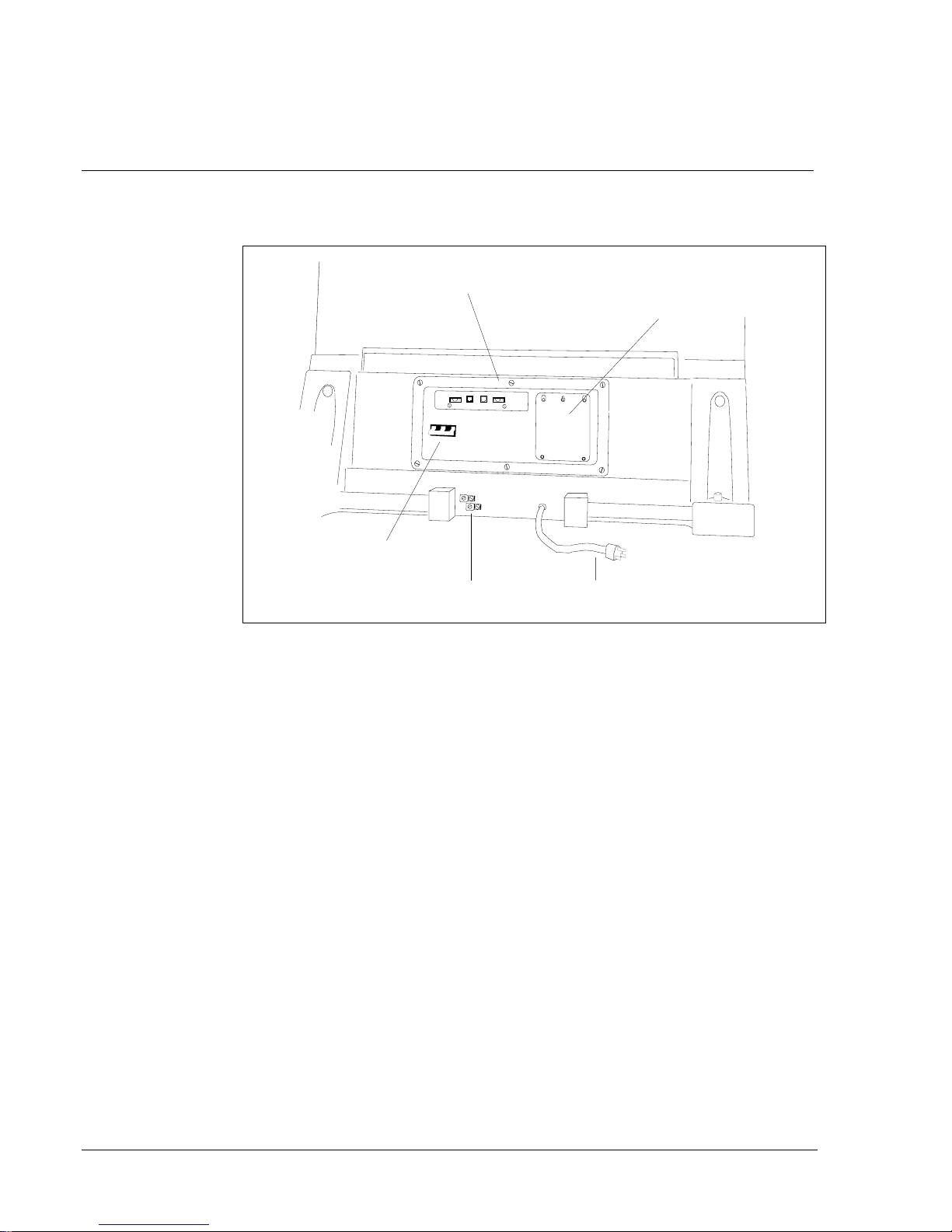
Figure 5xxx
PDU connections
J3 J6 J5 J4
Wiring access plate
Power Distribution Unit
Main circuit
breaker Ground lugs AC line cord
3Connect the safety ground wire.
Use insulated ground wire for system grounding.
For a direct connection, connect a #6 AWG wire from the ground
source in the service panel to a ground lug on the pedestal of the AEM
column.
For a daisy-chain connection, connect a #6 AWG wire from a ground
lug on the closest Meridian 1 column or cabinet to a ground lug on the
pedestal of the AEM column.
10 Installing a stand-alone AEM
553-3201-200 Standard 1.0 April 1993
Figure 5xxx
PDU connections
J3 J6 J5 J4
Wiring access plate
Power Distribution Unit
Main circuit
breaker Ground lugs AC line cord
3Connect the safety ground wire.
Use insulated ground wire for system grounding.
For a direct connection, connect a #6 AWG wire from the ground
source in the service panel to a ground lug on the pedestal of the AEM
column.
For a daisy-chain connection, connect a #6 AWG wire from a ground
lug on the closest Meridian 1 column or cabinet to a ground lug on the
pedestal of the AEM column.

Installing a stand-alone AEM 11
Application Equipment Module
Installation guide
Figure 6xxx
Meridian 1/AEM column daisy chain connection
From ground source To ground lug of
next column From last column
to power plant
4Measure the resistance between the ground pin on the power plug and
the ground terminal on the power outlet.
The resistance should be zero ohms. If the resistance is greater than .5
ohms, check the power outlet ground and safety ground connections.
5Remove the field wiring access plate on the PDU.
6Connect logic return wiring.
For a stand-alone column, make sure the logic return wiring, a 3-inch
shorting strap, #10 AWG or larger, connects the LRTN and GND
terminals on the field wiring block (see Figure 7).
For a multi-column row, connect a #8 AWG wire from the Logic Return
Equalizer (LRE) (used with the Meridian 1) to LRTN on the field wiring
block (see Figure 8).
7Replace the field wiring access plate on the PDU.
8Go to the appropriate procedure in “Alarm connections” to configure
and connect the NT8D22 System Monitor in the AEM column.
12 Installing a stand-alone AEM
553-3201-200 Standard 1.0 April 1993
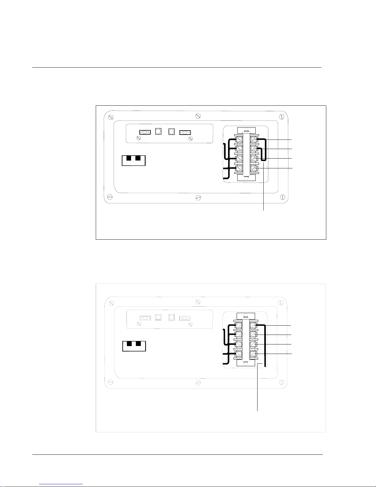
Figure 7xxx
AEM Logic return connection-LRTN/GND common connection for
stand-alone column
J3 J6 J5 J4
Three-inch
Shorting strap
(#10 AWG or larger)
LRTN
GND
L2
L1
Power distribution unit
Figure 8xxx
AEM Logic return connection-LRTN isolated star connection for a
multi-column row
J3 J6 J5 J4 LRTN
GND
L2
L1
To LRE
Power distribution unit
12 Installing a stand-alone AEM
553-3201-200 Standard 1.0 April 1993
Figure 7xxx
AEM Logic return connection-LRTN/GND common connection for
stand-alone column
J3 J6 J5 J4
Three-inch
Shorting strap
(#10 AWG or larger)
LRTN
GND
L2
L1
Power distribution unit
Figure 8xxx
AEM Logic return connection-LRTN isolated star connection for a
multi-column row
J3 J6 J5 J4 LRTN
GND
L2
L1
To LRE
Power distribution unit
Installing a stand-alone AEM 13
Application Equipment Module
Installation guide
Power connections (dc)
A stand-alone AEM column can be connected to the dc power plant used
with the Meridian 1 system.
Depending on the distances between columns and the service panel, you
may run safety ground wiring independently from the AEM column to the
service panel, or you may daisy-chain the safety ground wiring between the
AEM column and the Meridian 1.
WARNING
Risk of equipment damage
Failure to follow grounding procedures can result in
an unsafe or faulty system.
You must run all wiring (except cables to the system monitor) from the
external power equipment to the pedestal through flexible metallic conduit.
You may route a 3/4-inch conduit through four holes in the top or bottom of
the pedestal. The 3/4-inch conduit can contain a maximum of nine #10
AWG wires or five #8 AWG.
A maximum loop drop of two volts is allowed between the pedestal, or a
junction box, and the external power equipment. See Table 1 for allowable
wire sizes. See Power engineering (553-3001-152) for detailed
information on calculating wire size.

14 Installing a stand-alone AEM
553-3201-200 Standard 1.0 April 1993
Table 1xxx
Pedestal wire gauge requirements with two 30-amp 48 V dc feeds (see Note 1)
Length Single
conduit
#8 AWG
Dual conduit
#6 AWG
(Note 2)
Junction box
(single #4 AWG)
(Note 3)
Junction box
(double #4 AWG)
(Note 4)
0 - 3 m (10 ft) Yes Yes Yes Yes
0 - 6 m (20 ft) Yes Yes Yes Yes
0 - 9 m (30 ft) Yes Yes Yes Yes
0 - 12 m (40 ft) Yes Yes Yes Yes
0 - 15 m (50 ft) Yes Yes Yes Yes
0 - 18 m (60 ft) No Yes Yes Yes
0 - 21 m (70 ft) No Yes Yes Yes
0 - 24 m (80 ft) No Yes Yes Yes
0 - 27 m (90 ft) No No Yes Yes
0 - 30 m (100 ft) No No Yes Yes
0 - 60 m (200 ft) No No No Yes
over 60 m (200 ft) No No No No
Note 1:
Two 30-amp feeds are typically adequate for a column with four modules (five wires
total-two 30-amp battery/battery return pairs plus logic return).
Note 2:
When using dual conduit, the wires must be run in battery/battery return pairs, with
one pair in one conduit and the other pair, plus logic return, in the other conduit.
Note 3:
Five single runs of #4 AWG wire are used from the distribution point to the NT6D53
junction box near the pedestal; #10 AWG wire in a single conduit (supplied with the junction
box) is run from the junction box to the pedestal.
Note 4:
Five double runs of #4 AWG wire are used from the distribution point to the
NT6D53 junction box near the pedestal; #10 AWG wire in a single conduit (supplied with the
junction box) is run from the junction box to the pedestal.
Legend: Yes = Wire size is adequate for the distance
No = Wire size has too high a voltage drop and is inadequate for the distance.

Installing a stand-alone AEM 15
Application Equipment Module
Installation guide
Procedure 2xxx
Power connections (dc)
1Connect the safety ground wire.
Use insulated ground wire for system grounding.
For a direct connection, connect a #6 AWG wire from the ground
source in the service panel to a ground lug on the pedestal of the AEM
column.
For a daisy-chain connection, connect a #6 AWG wire from a ground
lug on the closest Meridian 1 column or cabinet to a ground lug on the
pedestal of the AEM column (see Figure 9).
Note:
If the power plant consists of a QBL12 used with
customer-provided power equipment, use a direct connection to
the service panel. Do not extend ground wiring from the Meridian
1/SL-1 frame to the power plant.
2Remove the PDU to access the field wiring terminal block (TB1) in the
bottom of the pedestal.
Figure 9xxx
Direct wiring connection-Meridian 1 to AEM
From ground source To ground lug of
next column Terminate
on last column
Other manuals for Meridian 1 PC Console Interface Unit
1
Table of contents
Other Northern Telecom Network Hardware manuals


Popular Network Hardware manuals by other brands

Black Box
Black Box ServSelect KV119A Installer/user guide

Checkpoint
Checkpoint 21000 Appliances G-70 Getting started guide

Black Box
Black Box DTX5000-CTL-R2 quick start guide

Watchguard
Watchguard Firebox T45-W-PoE quick start guide

Vanguard
Vanguard 6500 PLUS installation manual

Black Box
Black Box ME1240A-F manual


