Northern Telecom Meridian SL-1 User manual

Integrated Services Network
Meridian SL-1*
QCA144 1.5 MB/S Remote Peripheral
Equipment Cabinet
Description, Installation and Testing
Publication number: Appendix 1 to 553-2601-200
Document Status: Standard
Date: 88 06 10
© 1987 Northern Telecom
All rights reserved.
* Meridian and SL-1 are trademarks of Northern Telecom Limited
Appendix 1 to 553-2601-200

Contents
1. Description 1-1
Remote Peripheral Equipment (RPE) 1-1
QCA144 RPE cabinet 1-1
Expansion shelves 1-1
Power converters 1-2
Power line cords 1-2
Reserve batteries 1-3
Cooling units 1-3
Built-in cross connect terminal 1-3
2 Installation and connections 2-1
Environment 2-1
Grounding 2-1
Option and switch settings on circuit packs 2-1
Installation
Figure
1-1 Front View QCA144 RPE Cabinet 1-4
1-2 Front View Typical Common Equipment (CE) Cabinet 1-5
2-1 Ground Connection and Tests 2-5
2-2 Typical Terminal Block Layout 2-6
2-3 Built-in Cross Connect Terminal layout 2-7
2-4 RPE Cables C and D Cross Connections 2-8
2-5 Front View of RPE Cabinet 2-9
2-6 Shelf Assembly 2-21
2-7 Rear View of Cabinet 2-22
2-8 Battery Cell Connections 2-28
Contents Continued
iii
Appendix 1 to 553-2601-200

2-9 Reserve Power Supply Connections 2-29
2-10 Expansion Battery Unit Connections 2-30
2-11 P10 Cable Terminations and Designations 2-35
2-12 Cabinet Top Assembly 2-38
2-13 Cooling Unit Location and Connections 2-39
2-14 QBL15 Battery Distribution Box 2-45
2-15 Reserve Power Connections Outside Cabinet 2-46
2-16 Battery Sensing and Monitoring Connections 2-47
2-17 Local-To-Remote Cross-Connections 2-48
Charts
2-1 QCA144 RPE Cabinet Installation 2-4
2-2 QSD66 or QSD69 Expansion Shelf Installation 2-17
2-3 QBL24 Battery Unit Installation (Main Unit) 2-23
2-4 Expansion QBL24 Battery Unit Installation 2-26
2-5 QUA6 Power Fail Transfer Unit (PFTU) Installation 2-31
2-6 Alarm and Transfer Wiring (P10) Installation 2-32
2-7 QPC705 Power Converter Installation 2-36
2-8 QUD24 Fan Unit Installation 2-37
2-9 QCAD321 Junction Box Assembly Installation 2-40
2-10 QBL15 Battery Distribution Box Installation 2-44
Tables
2-A Peripheral Equipment Cable Terminating Sequence 2-15
2-B PFJ1 Emergency Transfer Cable Cross-connections 2-34
2-C Cable C Designations (Receive) Local and Remote 2-49
2-D Cable D Designations (Transmit) Local and Remote 2-50
Reason For Reissue: This Practice is reissued to include
additional information about cross-connections, to remove
references to rectifiers other than the QRF12 -48 V rectifier supplied
with the system and to make other minor changes. Changes are
indicated by a vertical bar in the margin next to the affected item.
iv Contents
Appendix 1 to 553-2601-200

1. Description
Remote peripheral equipment (RPE)
1.01 A description of the use and operation of RPE is given in 553-2601-
200.
1.02 This appendix describes the installation, connections and testing of
RPE installed in a QCA144 RPE cabinet and in a QSD69 RPE shelf
mounted in a cabinet either at the remote end or the local end.
QCA144 RPE cabinet
1.03 The QCA144 RPE cabinet is used to house RPE equipment at a
remote location. The single-tier base cabinet is equipped with an RPE shelf,
one PE shelf capable of accommodating ten PE line packs and a peripheral
buffer circuit pack, and the required power equipment ( Fig. 1-1). The base
cabinet can be expanded to a two- or three-tier cabinet by the addition of
one RPE or two PE expansion shelves. An RPE shelf can be installed in
place of a PE expansion shelf if additional network loops are required.
Expansion shelves
1.04 QSD69 RPE shelf. The QSD69 RPE shelf assembly can be mounted
at the Main Meridian SL-1 location in a QCA136 or QCA141 CE
equipment cabinet (Fig. 1-2) or in a QCA144 RPE cabinet at the remote
location. The RPE shelf assembly is designed to contain all the RPE related
circuit packs required to operate two network loops. Included in the shelf
assembly is a dual loop PE shelf containing eight slots for lines and trunks.
One additional slot is reserved for a dual loop peripheral buffer circuit pack.
1-1
Appendix 1 to 553-2601-200

1.05 QSD66 PE expansion shelf. The QSD66 PE expansion shelf can be
used to expand a QCA144 RPE cabinet to a two- or three-tier cabinet. The
QSD66 is equipped with two PE shelves each capable of accommodating
eight line circuit packs and one peripheral buffer circuit pack.
Note: Although the QSD66 PE expansion shelf provides dual-loop
capabilities, the shelf can only be used in a single-loop mode when
operating with RPE.
Power converters
1.06 QPC705 Power Converter. The QPC705 power converter supplies
+
15 V (for SL-1 and digital telephones) and -150 V (for message waiting)
to the PE shelf in the first tier of the cabinet. A QCAD278 cable is required
to connect the QPC705 converter.
1.07 QPC706 Power Converter. The QPC706 power converter provides
all the required power supplies to each PE shelf in the second and third tiers
of the cabinet. One converter is required for each PE shelf and is installed in
the designated slot on each shelf.
Power line cords
1.08 Three commercial power line cords can be used with the QCA144
RPE cabinet.
(a) A QCAD273 line cord is used when a 115 V 15A power supply is
provided. A NEMA type 5-15R power supply receptacle is required to
accommodate the line cord.
(b) A QCAD274 line cord is used when a 220 V 20A power supply is
provided. A NEMA type L6-20R power supply receptacle is required to
accommodate the line cord.
(c) A QCAD275 line cord is used when a 110 V 30A power supply is
provided. A NEMA type L5-30R power supply receptacle is required to
accommodate the line cord.
1.09 Power cords are connected to the rear of the -48 V rectifier in the
cabinet.
1-2 Description
Appendix 1 to 553-2601-200

Reserve batteries
1.10 One or two QBL24 battery units containing rechargeable dry cells can
be connected to the cabinet when service is required during commercial
power failures.
1.11 The cabinet can also be connected to lead acid batteries through a
QBL15 battery distribution box and a QCAD321 junction box assembly.
Cooling units
1.12 QUD24 Cooling Units are used to dissipate excess heat and are
required in cabinets equipped with three tiers.
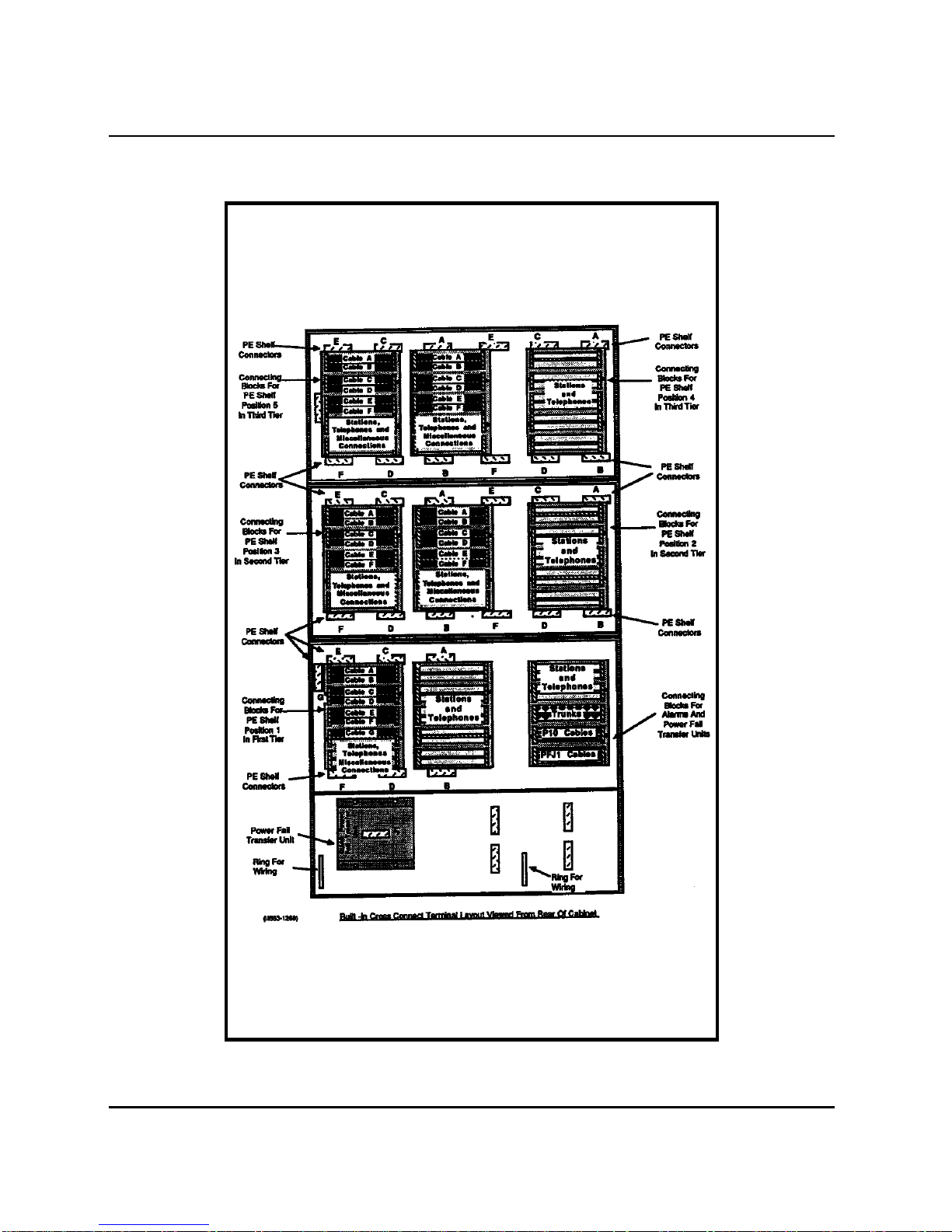
Built-in cross connect terminal
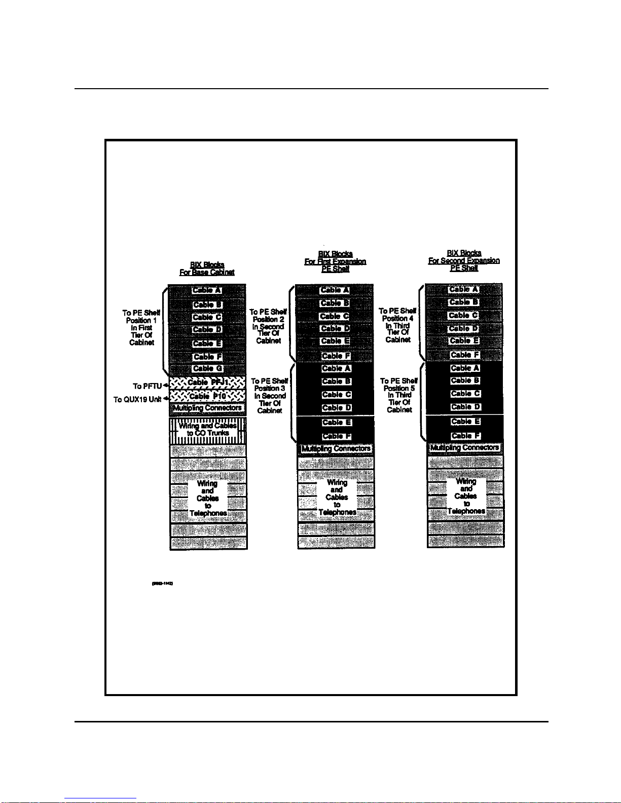
1.13 An optional built-in cross connect terminal using BIX* cable terminal
block system is available with cabinets equipped for suppression of EMI.
The built-in cross connect terminal, which is mounted on the EMI shields at
the rear of the cabinet, is accessible through the removal of the cabinet rear
covers. Connections to the system which would otherwise be made at an
external wall mounted or frame mounted terminal can be made using the
built-in cross connect terminal.
1.14 In a three tier cabinet the built-in cross connect terminal allows for
424 three-pair station wiring terminations plus additional connectors for
Power Fail Transfer Unit (PFTU) terminations. However, in cases where a
high density of 16-port line cards and/or four- or six-pair station cabling is
used, there may not be sufficient space to route or terminate all the wiring.
In these cases, additional external terminal blocks may be required. The
built-in cross connect terminal feature is not used in two cabinet
configurations.
* BIX is a trademark of Northern Telecom
Description 1-3
Appendix 1 to 553-2601-200
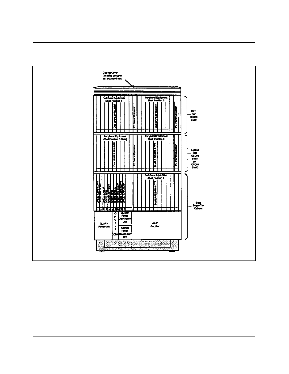
Figure 1-1
Front View QCA144 RPE Cabinet
Note: This position can be equipped with an RPE shelf when
additional RPE network loops are required.
(III.553-1266)
1-4 Description
Appendix 1 to 553-2601-200
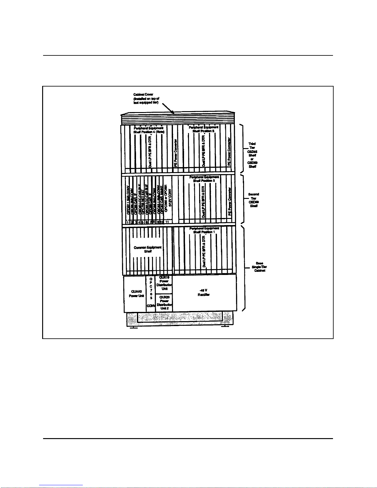
Figure 1-2
Front View Typical Common Equipment (CE) Cabinet
Note: This position can be equipped with a QSD69 RPE shelf when
additional RPE network loops are required.
(III.553-1267)
Description 1-5
Appendix 1 to 553-2601-200

2-1
Appendix 1 to 553 -2601-200
2. Installation and connections
Environment2.01 The QCA144 should be installed in an environment suitable for
Meridian SL-1. The location should be clean, dry and protected from
extreme heat or cold. The operating environment described in 553-2YY1-
200 for the location of the main Meridian SL-1 should be used as a guide
when installing the QCA144 RPE cabinet.
Grounding 2.02 The QCA144 cabinet must be connected to a suitable building ground
to ensure proper operation of the RPE equipment. Refer to 553-2YY1-200
for a description of suitable building grounds.
Option and switch settings on circuit packs
2.03 Certain circuit packs are equipped with option plugs or switches
located on the component side of the pack. Refer to 553-2201-211 for a list
of these circuit packs and the option settings.
Caution: Incorrectly set option plugs or switches on circuit packs
can prevent the system from operating properly and in certain cases
can cause system failure. Check option settings on all circuit packs
being installed in the cabinet.
Installation 2.04 Chart 2-1 describes the steps which should be followed when
installing a QCA144 RPE cabinet.

2-2 Installation and connections
Appendix 1 to 553-2601-200
2.05 Chart 2-2 describes the procedures which should be followed when
installing an additional QSD66 PE or QSD69 RPE shelf assembly in an
existing QCA144 RPE cabinet.
2.06 Chart 2-3 describes the procedures which should be followed when
installing a QBL24 Battery Unit.
2.07 Chart 2-4 describes the procedures which should be followed when
installing an expansion QBL24 Battery Unit.
2.08 Chart 2-5 describes the procedures which should be followed when
installing a QUA6 Power Fail Transfer Unit (PFTU).
2.09 Chart 2-6 describes the procedures which should be followed when
installing alarm and transfer wiring (P10).
2.10 Chart 2-7 describes the procedures which should be followed when
installing a QPC705 power converter.
2.11 Chart 2-8 describes the procedures which should be followed when
installing QUD24 cooling units.
2.12 Chart 2-9 describes the procedures which should be followed when
installing a QCAD321 junction box assembly.
2.13 Chart 2-10 describes the procedures which should be followed when
installing QBL15 battery distribution box.

Installation and connections 2-3
Appendix 1 to 553-2601-200
Chart 2-1
QCA RPE CABINET INSTALLATION
STEP PROCEDURE
1 Transport the cabinet as close as possible to its final location.
2 Transport the remaining equipment to a convenient safe dry location.
3 Unpack and inspect the cabinet.
4 Remove cabinet from pallet and place on floor.
5 If casters are provided, tilt the cabinet and replace the levellers on the cabinet with four
casters.
6 Adjust floor levellers or casters when in final location. When casters are provided,
ensure that they are locked in position when the cabinet is in its final location.
7 Remove the front and rear cabinet covers.
8 If required, install additional shelves as described in Chart 2-2.
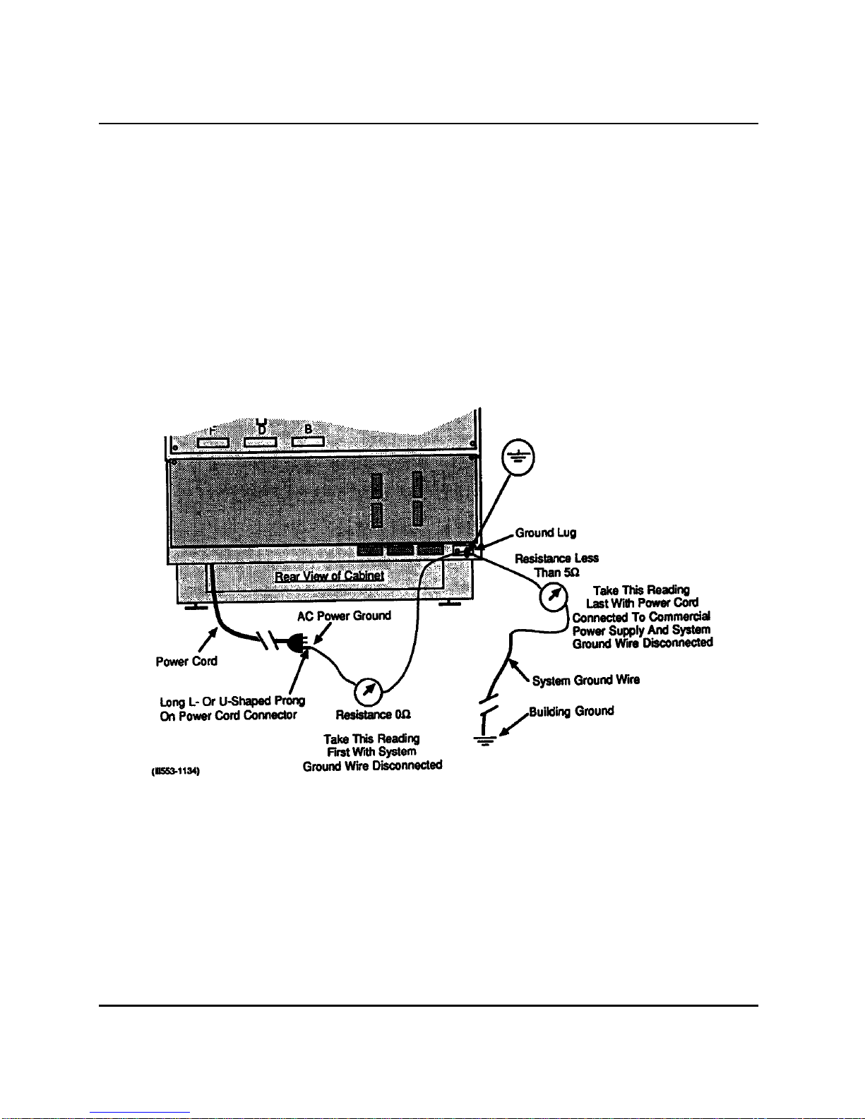
9 Install but do not connect a 6 AWG wire between the approved building ground and
the ground lug identified by a ground symbol (Fig. 2-1) at the rear of the cabinet.
10 At the building ground end of the wire, connect the 6 AWG wire to the approved
building using at least two fastening devices and insulate the connections with
electrical tape. Install a DO NOT DISCONNECT tag on the connection.
11 With an ohmmeter, measure the resistance between the ground pin on the ac power
cord plug and the ground lug at the rear of the cabinet (Fig. 2-1). The resistance should
be
0 Ω. If greater than 0 Ω, check power cord connections at rear of cabinet.
12 Ensure that the AC BRKR breaker on the faceplate of the -48 V rectifier in the cabinet
is set to OFF.
13 Connect the power line cord to the commercial ac power supply.
14 Measure the resistance between the system ground wire and the ground lug at the rear
of the cabinet (Fig. 2-1). If the resistance is greater than 5 Ω, check the building ground
and ac panel connections.
15 Disconnect the power line cord from the commercial ac power supply.
16 Connect the 6 AWG building ground wire to the ground lug identified by a ground
symbol at the rear of the cabinet (Fig. 2-1).
Chart Continued

2-4 Installation and connections
Appendix 1 to 553-2601-200
Chart 2-1 Continued
QCA RPE CABINET INSTALLATION
STEP PROCEDURE
17 If required, install reserve battery unit as described in Chart 2-3.
18 If cabinet is not equipped with a built-in cross connect terminal, install connecting
blocks at cross-connect terminal. A typical wall-mounted terminal block layout is
shown in Fig. 2-2.
19 If a QUA6 Power Fail Transfer Unit (PFTU) is provided, install unit as described in
Chart 2-4.
20 If required, install alarm and transfer (P10) wiring as described in Chart 2-5.
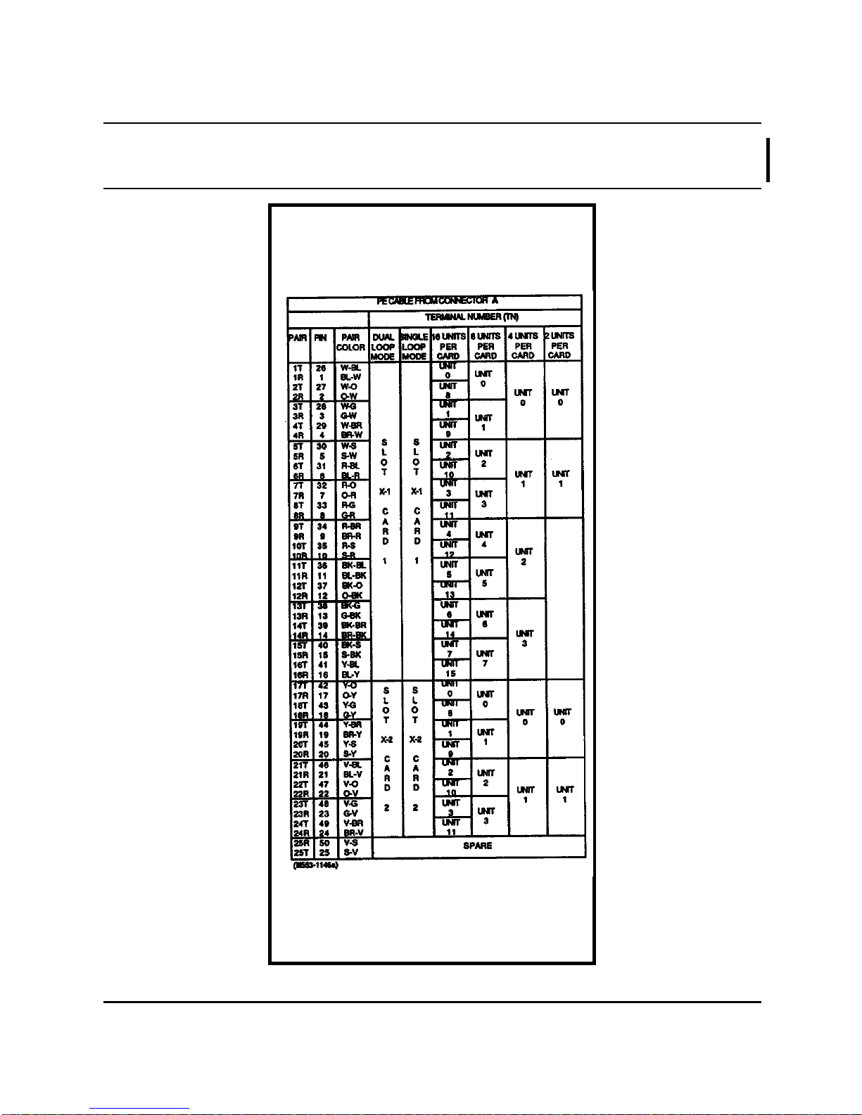
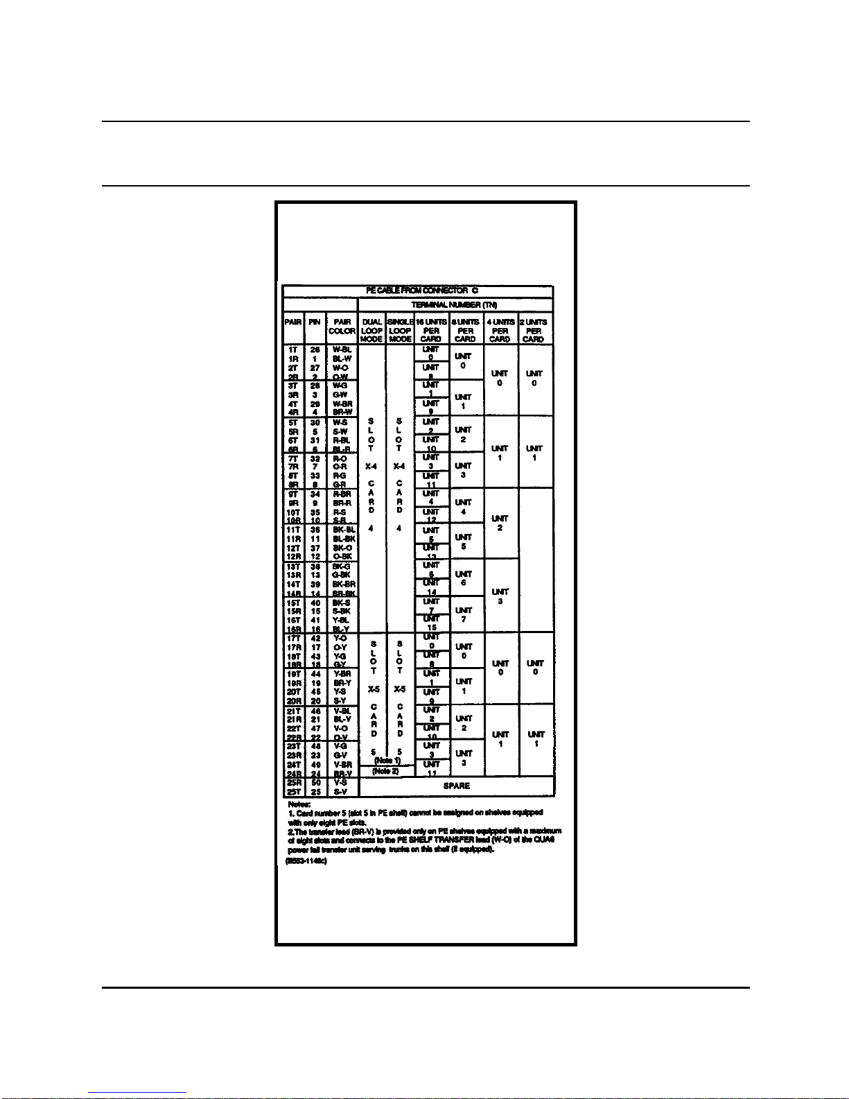
21 Install and terminate Peripheral Equipment (PE) cables to cross connect terminal.
Cable terminating sequence is given in Table 2-A.
Note: These cables are usually factory installed in cabinets equipped with a built-in cross
connect terminal (Fig. 2-3).
22 Install and terminate two NE A-25B-type cables from connectors C and D at the rear of
the RPE shelf to connecting blocks at an external crossconnect terminal. See Tables 2-
C and 2-D cable color terminating sequence and lead designations.
Note: Do not terminate RPE cables C and D on the built-in cross connect terminal.
23 Install cross connections for RPE cables C and D as shown in Fig. 2-4, Fig. 2-17 and in
Part 6 of 553-2601-200.
24 Ensure that the circuit packs are in their assigned position in the RPE shelf (Fig. 2-5).
25 Connect ac power line cord to commercial ac power supply.
26 Set all breakers at the front of the cabinet to ON.
27 Test RPE equipment as described in 553-2601-200.
28 Install front and rear covers on cabinet.
Installation and connections 2-5
Appendix 1 to 553-2601-200
Figure 2-1
Ground Connection and Tests
2-6 Installation and connections
Appendix 1 to 553-2601-200
Figure 2-2
Typical Terminal Block Layout
Installation and connections 2-7
Appendix 1 to 553-2601-200
Figure 2-3
Built-in Cross Connect Terminal Layout

2-8 Installation and connections
Appendix 1 to 553-2601-200
Figure 2-4
RPE Cables C and D Cross Connections
Installation and connections 2-9
Appendix 1 to 553-2601-200
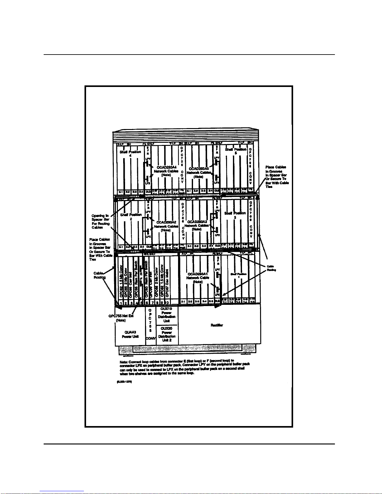
Figure 2-5
Front View of RPE Cabinet
2-10 Installation and connections
Appendix 1 to 553-2601-200
Table 2-A
PERIPHERAL EQUIPMENT CABLE TERMINATING SEQUENCE

Installation and connections 2-11
Appendix 1 to 553-2601-200
Table 2-A Continued
PERIPHERAL EQUIPMENT CABLE TERMINATING SEQUENCE
2-12 Installation and connections
Appendix 1 to 553-2601-200
Table 2-A Continued
PERIPHERAL EQUIPMENT CABLE TERMINATING SEQUENCE
Other manuals for Meridian SL-1
3
This manual suits for next models
1
Table of contents
Other Northern Telecom Network Hardware manuals


Popular Network Hardware manuals by other brands


Huawei
Huawei PDU8000 Series quick guide

Zinwell
Zinwell PWQ-5101C Quick installation guide

Avocent
Avocent SwitchView IP 1020 Installer/user guide

Matric
Matric CB-500LR Technical manual

D-Link
D-Link DSN-6000 Series Quick installation guide

Panasonic
Panasonic Schottky Barrier Diodes MA3Z7930G Specifications