Northern Tool and Equipment Ironton 75429 User manual

READ & SAVE THESE INSTRUCTIONS
2-in-1 Air Operated Grease Gun
Owner’s Manual
WARNING: Read carefully and understand all ASSEMBLY AND OPERATION
INSTRUCTIONS before operating. Failure to follow the safety rules and other basic safety
precautions may result in serious personal injury.
Item #75429

Page 2 of 19
Thank you very much for choosing an Ironton™product!
For future reference, please complete the owner’s record below:
Serial Number/Lot Date Code: ________________________________
Purchase Date: ____________________________________________
Save the receipt, warranty, and this manual. It is important that you read
the entire manual to become familiar with this product before you begin
using it.
This grease gun is designed for certain applications only. Northern Tool
and Equipment is not responsible for issues arising from modification or
improper use of this product such as an application for which it was not
designed. We strongly recommend that this product not be modified
and/or used for any application other than that for which it was designed.
For technical questions, please call 1-800-222-5381.

Page 3 of 19
Table of Contents
Intended Use..........................................................................................................................................4
Packaging Contents..............................................................................................................................4
Technical Specifications......................................................................................................................4
Important Safety Information...............................................................................................................4
Specific Operation Warnings...............................................................................................................6
Main Parts of Grease Gun....................................................................................................................7
Assembly Instructions..........................................................................................................................7
Before Each Use....................................................................................................................................9
Operating Instructions........................................................................................................................10
After Each Use.....................................................................................................................................14
Maintenance ........................................................................................................................................14
Troubleshooting..................................................................................................................................15
Parts Diagram......................................................................................................................................16
Parts List..............................................................................................................................................16
Replacement Parts..............................................................................................................................17
Limited Warranty.................................................................................................................................18
Page 4 of 19
Intended Use
The Ironton 2-in-1 Air Operated Grease Gun is a manual lever or air operated grease gun with 16 oz.
lubricant capacity.
Packaging Contents
•Main Housing
•1/4" NPTF I/M Type Quick
Coupler
•Manual Handle
•Tube Container
•Flexible Tube
•Rigid Tube
•Owner’s Manual
Technical Specifications
Property
Specification
Type
Manual Lever or Air Operation
Handle Type
Pistol Grip
Pressure Rating
1,600 to 6,000 PSI
Inlet Size
1/4 in. NPT
Air Hose
3/8 in. (inside diameter)
3-Way Loading
Cartridge Loading (16 oz.)
Bulk Loading (500 cc)
Filler Pump Loading
Capacity
16 oz.
Construction
Equipped with both a metal and flexible spout
Average Air Consumption
4 CFM @ 90 PSI
Important Safety Information
⚠WARNING
•Read and understand all instructions. Failure to follow all instructions may result in serious injury
or property damage.
•The warnings, cautions, and instructions in this manual cannot cover all possible conditions or
situations that could occur. Exercise common sense and caution when using this tool. Always be
aware of the environment and ensure that the tool is used in a safe and responsible manner.
•Do not allow persons to operate or assemble the product until they have read this manual and
have developed a thorough understanding of how it works.
•Do not modify this product in any way. Unauthorized modification may impair the function and/or
safety and could affect the life of the product. There are specific applications for which the
product was designed.
•Use the right tool for the job. DO NOT attempt to force small equipment to do the work of larger
industrial equipment. There are certain applications for which this equipment was designed. This
product will be safer and do a better job at the capacity for which it was intended. DO NOT use

Page 5 of 19
this equipment for a purpose for which it was not intended.
•Industrial or commercial applications must follow OSHA requirements.
⚠WARNING
WORK AREA SAFETY
•Inspect the work area before each use. Keep work area clean, dry, free of clutter, and well-lit.
Cluttered, wet, or dark work areas can result in injury. Using the product in confined work areas
may put you dangerously close to cutting tools and rotating parts.
•Do not use the product where there is a risk of causing a fire or an explosion; e.g., in the
presence of flammable liquids, gases, or dust. The product can create sparks, which may ignite
the flammable liquids, gases, or dust.
•Do not allow the product to come into contact with an electrical source. The tool is not insulated
and contact will cause electrical shock.
•Keep children and bystanders away from the work area while operating the tool. Do not allow
children to handle the product.
⚠WARNING
PERSONAL SAFETY
•Stay alert, watch what you are doing, and use common sense when operating the tool. Do not
use the tool while you are tired or under the influence of drugs, alcohol, or medication. A
moment of inattention while operating the tool may result in serious personal injury.
•Dress properly. Do not wear loose clothing, dangling objects, or jewelry. Keep your hair,
clothing and gloves away from moving parts. Loose clothes, jewelry, or long hair can be caught
in moving parts. Air vents on the tool often cover moving parts and should be avoided.
•Wear the proper personal protective equipment when necessary. Use ANSI Z87.1 compliant
safety goggles (not safety glasses) with side shields, or when needed, a face shield. Use a
dust mask in dusty work conditions. Also use non-skid safety shoes, hardhat, gloves, dust
collection systems, and hearing protection when appropriate. This applies to all persons in the
work area.
•Do not overreach. Keep proper footing and balance at all times.
•Remove keys or wrenches before connecting the tool to an air supply, power supply, or turning
on the tool. A wrench or key that is left attached to a rotating part of the tool may cause
personal injury.
•Secure the work with clamps or a vise instead of your hand when practical. This safety
precaution allows for proper tool operation using both hands.

Page 6 of 19
⚠CAUTION
GREASE GUN USE AND CARE
•Do not force the grease gun. Products are safer and do a better job when used in the manner
for which they are designed. Plan your work and use the correct product for the job.
•Check for damaged parts before each use. Carefully check that the product will operate
properly and perform its intended function. Replace damaged or worn parts immediately. Never
operate the product with a damaged part.
•Disconnect the power/air supply from the product and place the switch in the locked or off
position before making any adjustments, changing accessories, or storing the tool. Such
preventive safety measures reduce the risk of starting the tool accidentally.
•Store the product when it is not in use. Store it in a dry, secure place out of the reach of
children. Inspect the tool for good working condition prior to storage and before re-use.
•Use only accessories that are recommended by the manufacturer for use with your product.
Accessories that may be suitable for one product may create a risk of injury when used with
another tool. Never use an accessory that has a lower operating speed or operating pressure
than the tool itself.
•Keep guards in place and in working order. Never operate the product without the guards in
place.
•Do not leave the tool running unattended.
Specific Operation Warnings
⚠WARNING
•To prevent serious injury or property damage, read and understand owner’s manual before
operating.
•Always wear the proper protective equipment, including ANSI Z87.1 compliant eye protection.
•High Pressure Fluid Hazard. Do not use a hose pressure rating that is less than the grease
gun.
•Do not exceed the max pressure of 6000 PSI.
•DO NOT carry the gun by the air hose or yank the hose from the air supply.
•Grease is delivered at high pressure. DO NOT point the grease outlet at yourself or others.
•When not in use, disconnect from air supply and store in a safe, dry, and childproof location.

Page 7 of 19
Main Parts of Grease Gun
Subassembly
Main Housing
Connector
Rigid Coupler Assembly or Flexible Hose Assembly
Tube Container
Manual Handle
Assembly Instructions

Page 8 of 19
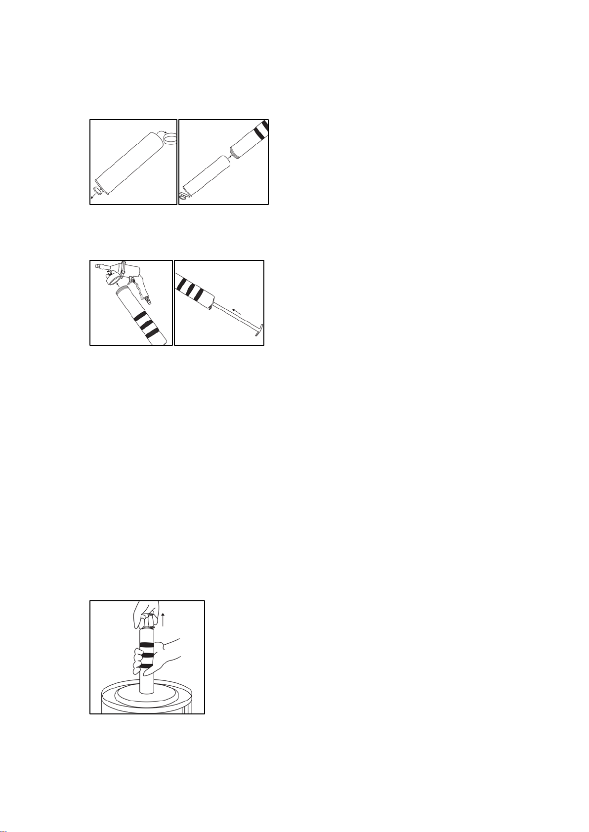
Pneumatic Use Assembly
•Attach the flexible hose or rigid coupler to the main housing. See Figure 1.
Figure1
•Insert the tube container into the main housing. See Figures 2 and 3.
Figure 2 Figure 3
Manual Lever Grease Gun Assembly
•Attach the rigid coupler assembly (#10) or flexible hose assembly (#10b) to the manual handle
(#24), See Figure 4.
Figure 4

Page 9 of 19
•Attach the manual handle (#24) to the tube container (#19). See Figure 5.
Figure 5
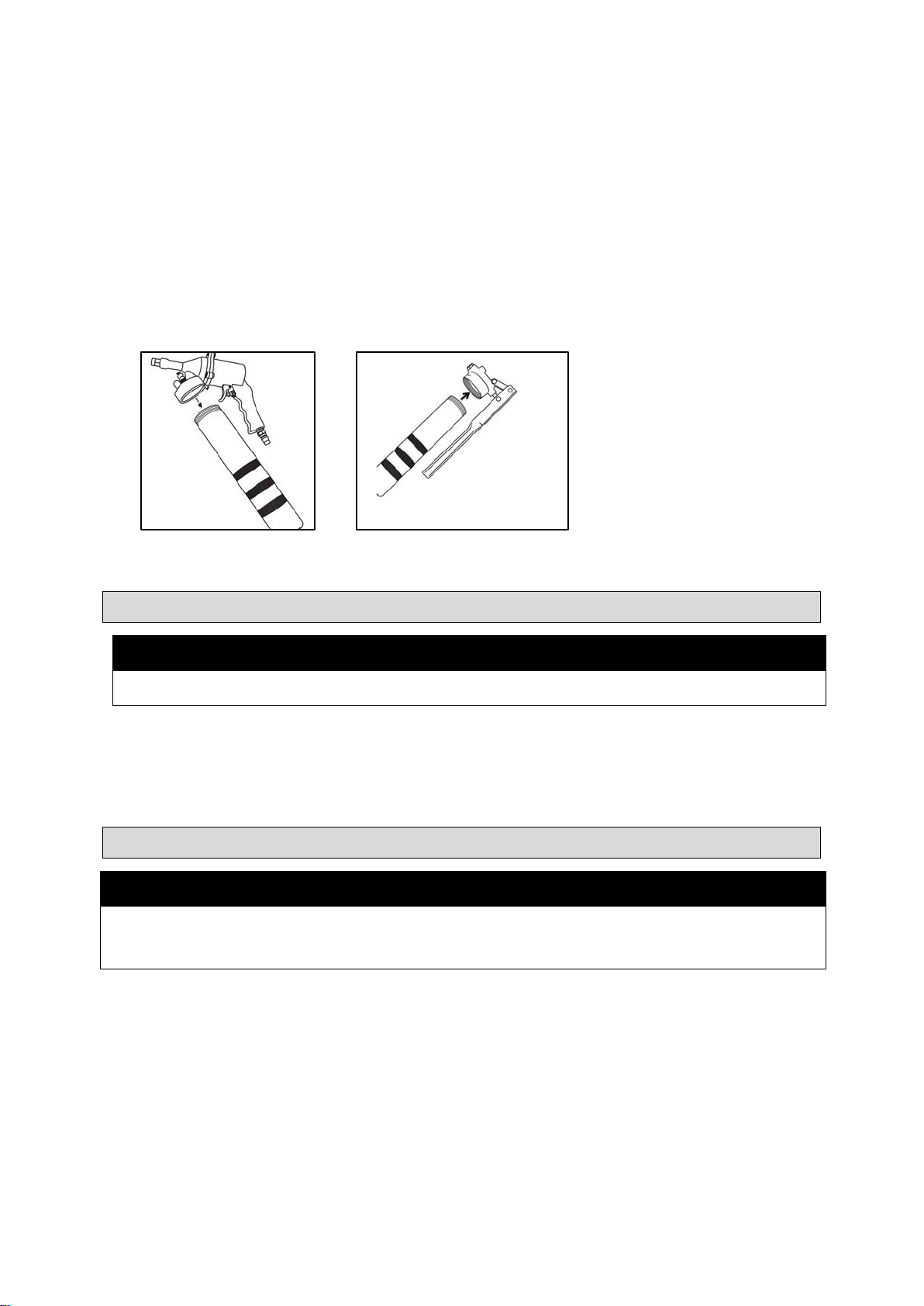
The completed assembly is shown below in Figures 6 and 7.
Figure 6 Figure 7
Before Each Use
⚠WARNING
•Disconnect from air supply before changing accessories or servicing.
Before each use, prime the grease gun by following the Operation Instructions until grease flows from
the tip (#10a). If the grease gun does not prime properly, follow the instructions below for venting
trapped air. Inspect the overall condition of the grease gun and look for:
•a damaged hose,
•loose hardware,
•misalignment or binding of moving parts,
•cracked or broken parts,
•damaged electrical wiring, or
•any other condition that may affect its safe operation.
Venting Trapped Air
•Remove the gun body from the tube container by turning counter-clockwise.
•Install the manual handle to the tube container by turning clockwise. Make sure that the manual
handle is mounted securely onto the tube container.
•Pull up and then depress the lever of the manual handle to inject a small amount of grease.
•Repeat until enough grease is released.

Page 10 of 19
Operating Instructions
⚠WARNING
•Always wear the proper protective equipment, including ANSI Z87.1 compliant eye protection.
•High Pressure Fluid Hazard. Do not use a hose pressure rating that is less than the grease gun.
•Do not exceed the max pressure of 6000 PSI.
•Ensure that the trigger is in the OFF position when connecting to the air supply.
Setting up the Air Line for Operation
•Make sure that the air compressor being used for the air tool operation supplies the correct output
(CFM).
•Have the tool in the “off” position when connecting the tool to the air supply.
•Use normal 90 psi working pressure for best tool performance while running the tool. High
pressure and unclean air will shorten the tool life due to faster wear and also may create a
hazardous situation.
•Drain water from air compressor tank daily, as well as any condensation in the air lines. Water in
the air line may enter the tool and damage the tool’s mechanisms.
•Clean the air inlet filter cartridge weekly. The recommended hook-up procedure can be viewed in
the following diagram.
•Line pressure should be increased accordingly to make up for extra-long air hoses (over 26 feet in
length). The minimum hose diameter should be 1/4 in. (inner diameter) and the fittings should
have the same inside dimensions. 3/8in. I.D. air hose is recommended for optimal performance.
Use proper hoses and fittings. A quick coupler connected directly to the tool is not recommended,
as vibrations may cause connection failure. Instead, add a leader hose and connect coupling
between air supply and hose whip.
•Check hoses for wear before each use. Make certain that all connections are secure.

Page 11 of 19
Air System Layout
○
1 Air grease gun
○
2 Air Hose 3/8” (I.D.)
○
3 Oiler
○
4 Pressure Regulator
○
5 Filter
○
6 Shut Off Valve
○
7 Whip Hose
○
8 Coupler Body and Connector
○
9 Drain Daily
○
101/2” or Larger Pipe and Fitting
○
11 Air Dryer
○
12 1” or Larger Pipe and Fitting
○
13 Air Compressor
○
14 Auto Drain
○
15 Drain Daily
Cartridge Loading
•Remove the tube container (#19) from the gun body. See Figure 8.
Figure 8
•Pull back on the tube handle (#22) until it is fully extended. Lock it into place with the locking plate
(#23). See Figure 9.
Figure 9
Page 12 of 19
•Remove the cap and/or lid from both ends of the cartridge (not included). Insert the cartridge into
the tube container in the orientation indicated on the cartridge. Make sure that the cartridge is as
far in as possible. See Figures 10 and 11.
Figure 10 Figure 11
•Reconnect the tube container to the gun body. Press the locking plate to release the handle.
Press the handle in as far as it will go. See Figures 12 and 13.
Figure 12 Figure 13
•Make sure that the end of the grease cartridge that is inserted into the tube container is not
damaged or squeezed and is still round. If not, the plunger will be prevented from entering the
grease cartridge, which will prevent the grease from coming out of the tube.
Note: Do not re-use empty grease cartridges.
Bulk Loading
Refer to Figure 14.
•Remove the tube container (#19) from the gun body.
•Submerge the open end of the tube container approximately 2 inches into the grease container
(not included).
•Pull back slowly and extend the tube handle (#22) fully to draw grease upward into the tube
container. Lock the handle into place with the locking plate (#23) when it is fully extended.
•Reassemble the tube container to the gun body. Press the locking plate to release the handle.
Press the handle in as far as it will go.
Figure 14

Page 13 of 19
Filler Pump Loading
Refer to Figure 15.
•Pull back on the tube handle (#22) until it is fully extended. Lock it into place with the locking plate
(#23).
•Insert the filler plug on the end of the hose of a filler pump (not included) into the fill nozzle (#12)
of the grease gun.
•Follow the operating instructions provided in the filler pump manual (not included) to work the filler
pump until the tube container (#19) of the grease gun is full.
•Disconnect the grease gun from the filler pump.
•Press the locking plate to release the handle. Press the handle in as far as it will go.
Figure 15
Operating the Grease Gun
•Attach the rigid coupler assembly (#10) or the flexible hose assembly (#10b) to the grease gun
connector (#9). See Figure 16.
•Connect an air supply to the grease gun. Set the working pressure to be 90 PSI for the best
operation of tool.
NOTE: Use either the rigid coupler assembly or the flexible hose assembly depending on need and
project.
•Press the trigger (#4) to inject a small amount of grease. Release and press the trigger repeatedly
to inject more grease. See Figure 17.
•Disconnect the air supply from the grease gun before refilling it.
Figure 16 Figure 17
Page 14 of 19
Using the Manual Grease Gun
This air-powered grease gun can be used as a manual grease gun with the manual handle.
•Remove the gun body from the tube container by turning it counter-clockwise. See Figure 18.
•Fill the tube container with grease by following the Grease Loading instructions.
•Attach the manual handle (#24) to the tube container by turning it clockwise. Make sure that the
manual handle is mounted onto the container tube tight and secure. See Figure 19.
•Pull up and then depress the lever of the manual handle to inject a small amount of grease.
Repeat until more the desired amount of grease is emitted.
Figure 18 Figure 19
After Each Use
⚠WARNING
•After each use, disconnect from air supply and store in a safe, dry, childproof location.
•Clean leftover grease from the tube container (#19) after each use.
•Clean the fill nozzle (#12) and the tip (#10a) of dirt, grease, or debris.
•Clean the entire grease gun with a cloth.
Maintenance
⚠WARNING
•The grease gun may still have air pressure after disconnected from air supply. Point the grease gun
into a suitable receptacle and fire it until all the air in the grease gun has been expended.
Page 15 of 19
Maintain the grease gun by adopting a program of conscientious repair and maintenance in
accordance with the following recommended procedures. It is recommended that the general
condition of any tool be examined before it is used. Keep your grease gun in good repair. Keep
handles dry, clean, and free from oil and grease. The following chart is based on a normal operation
schedule.
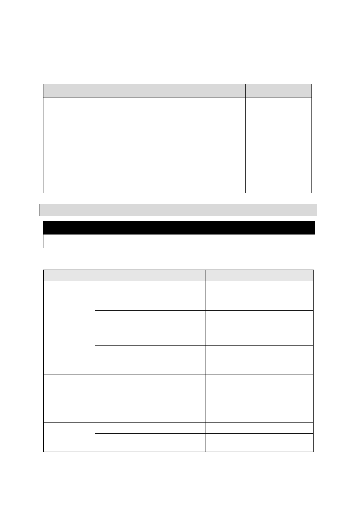
Maintenance Interval
Maintenance Point
Action
Daily before operating, after the first
20 operating hours, and after the
first 50 operating hours or every
week:
Check for:
•a damaged hose,
•loose hardware,
•misalignment or binding of
moving parts,
•cracked or broken parts,
•damaged electrical wiring,
•any other condition that may
affect its safe operation.
If damaged, replace
the parts before use.
Troubleshooting
⚠WARNING
•After each use, disconnect from air supply and store in a safe, dry, childproof location.
Use the table below to troubleshoot problems before contacting service personnel or your local
dealer. If the problem continues after troubleshooting, call your local dealer for assistance.
Failure
Possible Cause
Corrective Action
The grease gun
does not work.
Low air pressure.
Set the air pressure to 30 - 100 PSI.
Working pressure of 90 PSI is
recommended for the best operation.
Air hose leaks.
Check and see if the air hose is in
good condition. Tighten and seal hose
fittings using thread sealant tape if
leaks are found.
Springs (#7 and #18) and/or piston
assembly (#6) are damaged.
Replace springs and/or piston
assembly if they are damaged.
The grease gun
cycles and does
not pump
grease.
Grease gun is out of grease.
Refill the grease gun if it is out of
grease.
Repeat priming operation.
Disconnect any extensions and prime
until grease flows.
The grease gun
continues to lose
prime.
Trapped air in the grease gun.
Release trapped air in the grease gun.
Grease gun is out of grease.
Refill the grease gun and repeat
priming.

Page 16 of 19
Parts Diagram
Parts List
Part Number
Part Description
Quantity
1
Main housing
1
2
Air inlet
1
3
Trigger assembly
1
4
Trigger
1
5
Set screw
4
6
Piston assembly
1
7
Spring
1
8
Front housing
1
9
Connecter
1
10
Rigid coupler assembly
1
10a
Tip
1
10b
Flexible hose assembly
1
11
Air vent valve
1
12
Fill nozzle
1
13
Gasket
1
14
Lock nut
1
15
Washer
1
16
Plunger
1
17
Backlash gasket
1
18
Spring
1
19
Tube container
1
20
Container cap
1
21
Follower rod
1
22
Tube handle
1
23
Locking plate
1
24
Manual handle
1

Page 17 of 19
Replacement Parts
•For replacement parts and technical questions, please call Customer Service at 1-800-222-5381.
•Not all product components are available for replacement. The illustrations provided are a
convenient reference to the location and position of parts in the assembly sequence.
•When ordering parts, the following information will be required: item description, item model
number, item serial number/item lot date code, and the replacement part reference number.
•The distributor reserves the rights to make design changes and improvements to product lines
and manuals without notice.

Page 18 of 19
Limited Warranty
Northern Tool and Equipment Company, Inc. ("We'' or ''Us'') warrants to the original purchaser only
(''You'' or ''Your'') that the Ironton product purchased will be free from material defects in both
materials and workmanship, normal wear and tear excepted, for a period of one year from date of
purchase. The foregoing warranty is valid only if the installation and use of the product is strictly in
accordance with product instructions. There are no other warranties, express or implied, including the
warranty of merchantability or fitness for a particular purpose. If the product does not comply with this
limited warranty, Your sole and exclusive remedy is that We will, at our sole option and within a
commercially reasonable time, either replace the product or product component without charge to You
or refund the purchase price (less shipping). This limited warranty is not transferable.
Limitations on the Warranty
This limited warranty does not cover: (a) normal wear and tear; (b) damage through abuse, neglect,
misuse, or as a result of any accident or in any other manner; (c) damage from misapplication,
overloading, or improper installation; (d) improper maintenance and repair; and (e) product alteration
in any manner by anyone other than Us, with the sole exception of alterations made pursuant to
product instructions and in a workmanlike manner.
Obligations of Purchaser
You must retain Your product purchase receipt to verify date of purchase and that You are the original
purchaser. To make a warranty claim, contact Us at 1-800-222-5381, identify the product by make
and model number, and follow the claim instructions that will be provided. The product and the
purchase receipt must be provided to Us in order to process Your warranty claim. Any returned
product that is replaced or refunded by Us becomes our property. You will be responsible for return
shipping costs or costs related to Your return visit to a retail store.
Remedy Limits
Product replacement or a refund of the purchase price is Your sole remedy under this limited warranty
or any other warranty related to the product. We shall not be liable for: service or labor charges or
damage to Your property incurred in removing or replacing the product; any damages, including,
without limitation, damages to tangible personal property or personal injury, related to Your improper
use, installation, or maintenance of the product or product component; or any indirect, incidental or
consequential damages of any kind for any reason.
Assumption of Risk
You acknowledge and agree that any use of the product for any purpose other than the specified
use(s) stated in the product instructions is at Your own risk.
Governing Law
This limited warranty gives You specific legal rights, and You also may have other rights which vary
from state to state. Some states do not allow limitations or exclusions on implied warranties or
incidental or consequential damages, so the above limitations may not apply to You. This limited
warranty is governed by the laws of the State of Minnesota, without regard to rules pertaining to
conflicts of law. The state courts located in Dakota County, Minnesota shall have exclusive jurisdiction
for any disputes relating to this warranty.

Page 19 of 19
Distributed by:
Northern Tool & Equipment Company, Inc.
Burnsville, Minnesota 55306
www.northerntool.com
Made in China
Table of contents


