Northern EOCCPK User manual

1
MODEL: EOCCPK Ethernet Power Over Coaxial Master/Slave Transceiver
Description:
The EOCCPK is designed to extend IP Ethernet transmission and forward power over coaxial cable to
IP POE cameras. The EOCCPK has a transmission distance up to 600m/1968ft (RG6) and is extremely
simple to use. Status LEDs indicate power and link connectivity/activity for RJ45 ports.
Features:
No PC required, plug & play design reduces the cables and power distribution cost
Transmits IP camera signals or other 10/100 Base-T Full Duplex IP devices over coaxial cable
Injects power over an existing coaxial cable to IP POE cameras
Up to 600 Meter transmission distance when using RG6 cable / 1640ft. using RG59 cable
Built-in 6KV surge protection at BNC and 4KV at RJ45 ports
SPECIFICATIONS:
MODEL
EOCCPK
Extender Interface
Connector Type
1x BNC
Cable Type
75-ohm RG59, RG6, or RG11 video-grade coaxial cable
Max. Transmission Distance
600m (1968ft.) for RG6 coaxial cable / 500m (1640ft.) for RG59
Ethernet Interface
Connector Type
1x RJ-45 with LEDs on Connector
Cable Type
Straight through or cross-over Cat5/Cat6 Cable, Auto MDI/MDIX
Rate
IEEE 802.3x, Auto-Detection for 10/100Base-T and full/half
duplex
Output Voltage
IEEE 802.3af/at PSE@ RJ45 Port
Control & Indicators
Color LED Indicator for Coaxial
Data Signal Strength
Green:GOOD (Link speed > 60 Mbps)
Amber:MEDIUM (Link speed 20~60Mbps)
Red:BAD (Link speed < 20Mbps)
OFF:NO LINK
Yellow LED (On RJ45)
Power On
Green LED (On RJ45)
Link/Act.

2
Pairing Push Button
Reset / Pairing (Join or Leave Network Group)
Push
Duration
LED
Status
Description
1 –3 sec
Red Blink
Join/Host Network Group
5 –8 sec
Amber Blink
Once -> OFF
Leave Network Group
12 - 30 sec
OFF -> Amber
Blink Once
Reset to Default Network
Group
Power
Input Operating Voltage
DC 56V / 65W (Included)
Power Consumption
1.5W (w/o power forwarding)
Mechanical & Environmental
Weight
176g (6.2 oz)
Dimensions (W × L × H)
38 x120 x 33mm (1.5”x4.7”x1.3”)
Operation Temperature
-20C ~ +60°C (-4°F ~ 140°F)
Storage Temperature
-30C ~ 80C (-22°F ~ 176°F)
Humidity
20% to 85% RH. (non-condensing)
1. All EOCCPK are paired to the same network group by factory default, they can be installed directly with no
need for pairing again.
2. The transmission system consists of one transceiver at NVR side and one transceiver that connects to IP
cameras or other IP devices.
3. When using two or more transmission systems at the NVR or Control room –if there is no cross-talk
between the two systems then there is no need to perform the pairing process.
4. To join another network group, must leave current group first, then do the group join.
Transmission Distance with Power Delivered:
Power Delivered
Power Source
Not using
PoE output
5.5W
7W
9W
12W
17W
Maximum Coax RG6. Data Link Distance
56VDC Power Supplied
2000m
600m
500m
400m
300m
200m
Maximum Coax RG59. Data Link Distance
1800m
500m
450m
350m
250m
150m
Packing
1. EOCCPK Transceiver ×2
2. User Manual ×1
3. Wall Mount Hardware Kit ×2
4. DC 56V / 65W Power Adaptor ×1

3
PANEL DESCRIPTIONS:
1. DC56V IN: Power Supply DC56V/65W (Included).
2. PoE: Ethernet Interface (10/100Mbps for full duplexer), for PoE Output to camera
3. ACT./LINK: Data Link for indicaon LED
4. POWER: Power On for indicaon LED
5. SIGNAL STRENGTH: G(Green):GOOD
A(Amber):MEDIUM
R(Red):BAD
OFF:NO LINK
6. COAX DATA: Coaxial Transmission with High Voltage
7. PAIRING/RESET: PAIRING for network group join/leave / RESET for factory default network group
CONNECTION DIAGRAM:
Noce: Cable quality, camera bandwidth used and power supply noise can cause actual distances which
may not match the diagram below.
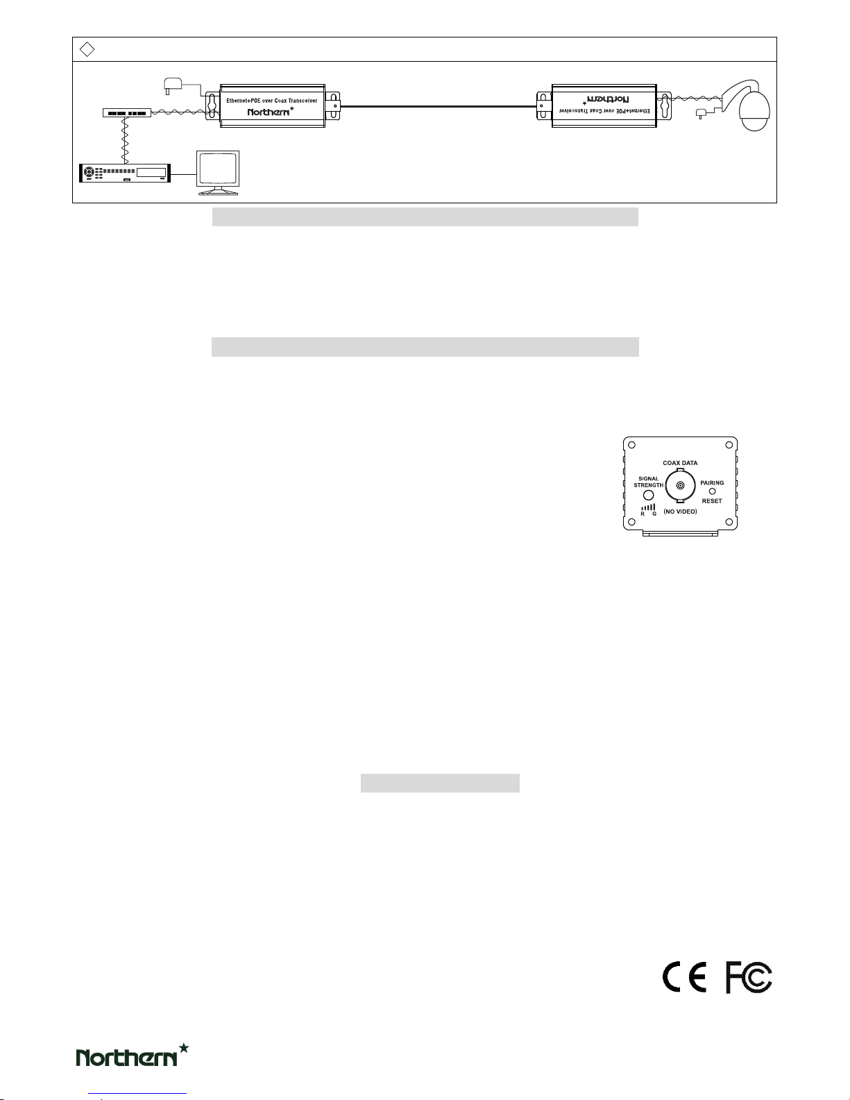
◆Applicaon Diagram 1: Single Camera EoC with PoE Transmission System
◆Applicaon Diagram 2:
Single Camera EoC with PoE Transmission System Alternate Power Supply Locaon
Monitor
DC 56V/65W
Max 600m (RG6)
NVR
Switch P
Ethernet Over Coaxial Transceiver with PoE
Ethernet Over Coaxial Transceiver with PoE
PoE
PoE Camera
P
Monitor
NVR
Switch P Max 600m (RG6)
Ethernet Over Coaxial Transceiver with PoE
DC 56V/65W
Ethernet Over Coaxial Transceiver with PoE
PoE
PoE Camera
P
4
◆Applicaon Diagram 3: Single Camera w/ External Power Supply EoC Transmission System (No PoE)
Before starng the pairing process, please check the noce below
1) If only setup one transmission system at NVR or control room side there is no need to do pairing
process.
2) When using two or more transmission systems at the NVR or Control room – if there is no cross-talk
between the two systems then there is no need to perform the pairing process.
EoC Transmission System Network Group Pairing Instrucons
Step 1: Setup EoC Transmission System
♦Connect all the coaxial, cat. 5e cables between transceivers, setup cameras and NVR then power
supplied to the system that one of the applicaon diagrams.
Step 2: Host/Master Side Leaving Current Network Group
♦On the transceiver at NVR side, using a straightened paper-clip
push the small buon for 5 ~ 8 seconds, the LED color will
turn AMBER blink once then turn OFF.
Step 3: Host/Master Side Create an New Network Group
♦On the transceiver at NVR side, using a straightened paper-clip to push the small buon for 1 ~ 3
seconds, the LED color will turn RED and start blinking.
Step 4: Slave Side Transceiver Leaving Current Network Group
♦On the transceiver at the Remote side (close to IP camera/device), using a straightened paper-clip to
push the small buon for 5 ~ 8 seconds, the LED color will turn AMBER blink once then turn OFF.
Step 5: Slave Side Transceiver Joining New Network Group
♦EOC transceivers at Remote side (close to IP camera/device, using a straightened paper-clip to
push the small buon for 1 ~ 3 seconds, the LED color will begin blinking RED. The transceivers will
find each other and starng the transmission.
In Pairing Process Noce
1) In joining or leaving process, if you are not sure that joining or leaving has been successful, you can
RESET the transceiver (press the push buon 12 to 30 seconds) , and repeat above steps.
2) Aer re-applying power or RESETING the transceiver, please wait for the color LED to start blinking
Amber once then turn GREEN, this means the power on reset finished and you can now start the
pairing process.
3) If the transceiver is in LEAVE to JOIN state (color LED blinking RED), it must join new network group
within 2 minutes or it will revert to a LEAVE state again.
Monitor
DC 56V/65W
Max 2000m (RG6)
NVR
Switch
IP Camera
P
P
Ethernet Over Coaxial Transceiver with PoE
Ethernet Over Coaxial Transceiver with PoE
Popular Transceiver manuals by other brands

Kenwood
Kenwood ProTalk TK-3201 instruction manual

City Theatrical
City Theatrical SHoW DMX SHoW Baby user manual

Standart Horizont
Standart Horizont HX407 owner's manual

B&G
B&G V90S quick start guide

VictelGlobal
VictelGlobal ALK300 series Operation manual

Cactus
Cactus Wireless Flash Transceiver V6 user manual


