NORTHMAN 2500 Series Troubleshooting guide

INSTALLATION & OPERATING
GUIDE
NORTHMAN 2500 SERIES SNOWPLOW
STRAIGHT BLADE APPLICATIONS
STEEL OR POLY MOLDBOARDS
Form 46250A
NORTHMAN MODEL 2500
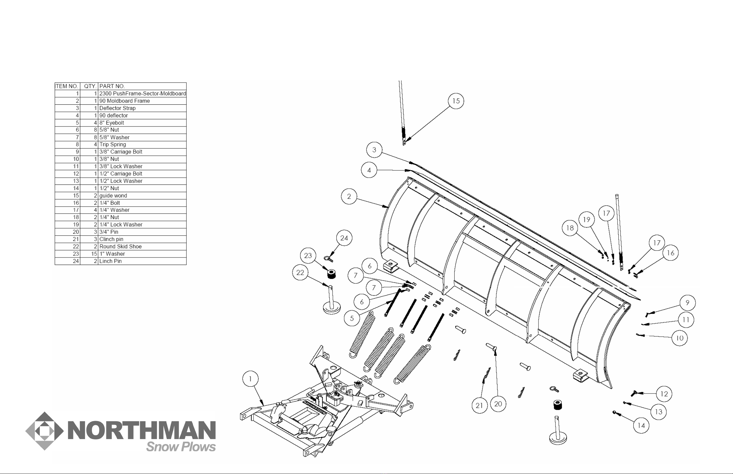
ASSEMBLY DIAGRAM
Form 46250A

THE PROFESSIONAL CHOICE
WARNING
This vehicle may be equipped with air bags. DO NOT under any circumstances disable,
remove or relocate any sensors or other components related to the operation of the air bags.
Vehicle Front Gross Axle Weight Rating (FGAWR), Rear Gross Axle Weight Rating (RGAWR),
and the Gross Vehicle Weight Rating (GAWR) must not be exceeded at any time to maintain
compliance with Federal Regulations and assure a safe vehicle. It is the operator’s
responsibility to verify that these ratings are not exceeded.
Consult your vehicle operation manual for additional specifications and warnings.
Make sure plow is properly attached before operating vehicle.
Always disconnect battery prior to beginning the installation.
Thank You for your purchase of a quality Northman product! At Northman, our
mission is to design and manufacture products that provide years of trouble free service
at the best possible value. All Northman products are designed and fully tested to meet
the needs of the serious professional. And our products are backed up with a
knowledgeable customer service and support network.
Please take a few minutes to review this manual and learn the basics of your new
Northman plow. Take important note of all warnings and maintenance requirements. If
you have further questions, your contact your Northman dealer for the latest product
and service information.

Page 2 of 6
Snowplow Assembly & Setup
Unpack all components and familiarize yourself with the various parts and assemblies
included in your new plow package. Mountings, electrical, and hydraulic assemblies
may have independent instructions and manuals specifically related to those products.
Basic Assembly
1. Assemble the Power Angling Assembly (1) to the moldboard assembly using
three Pivot Pins (20) and Cotter Pins (21). Install Trip Springs to sector ears.
Thread 5/8” Hex Nut on Spade Bolts () nearly to the bottom of threads. Loop
spade bolt holes through trip spring ends and insert threads through moldboard
bracket holes. Secure spade bolts with 5/8” flat washer and nuts. Adjust initial
spring tension by tightening 4 complete turns beyond taut. Tighten the lower jam
nut against the moldboard bracket to lock in place. Insert the Jackstand
Assembly into the pushframe bracket and engage the stand so that the assembly
sits level.
2. Remove Pump Cover from the power angling assembly. Install Left and Right
Power Angling Hoses to Hydraulic Pump Unit and Power Angling Cylinders.
Consult hydraulic and pump schematics for specific hookup information. Use
Teflon pipe sealant to insure proper hydraulic sealing.
3. Install the end link of the Lift Chain to the Push Frame using a 1/2” X 2” cap
screw, two 1/2” flat washers, and 1/2” locknut. Install the Safety Chain as shown
using the same procedure.
4. Remove the Attachment Pins and Attachment Bar Assembly from the Front Lift.
Set the Attachment Bar Assembly and Attachment Pins aside for use in vehicle
mounting installation. Attach the Lift Channel to the Front Lift using upper
attachment ears as shown. Install the 90 deg Hydraulic Elbow to inlet port on the
Lift Cylinder. Position the Lift Cylinder between the lower attachment ears of the
Front Lift and Lift Channel. Secure using hardware as shown. NOTE – DO NOT
OVERTHIGHTEN LOCKNUTS.
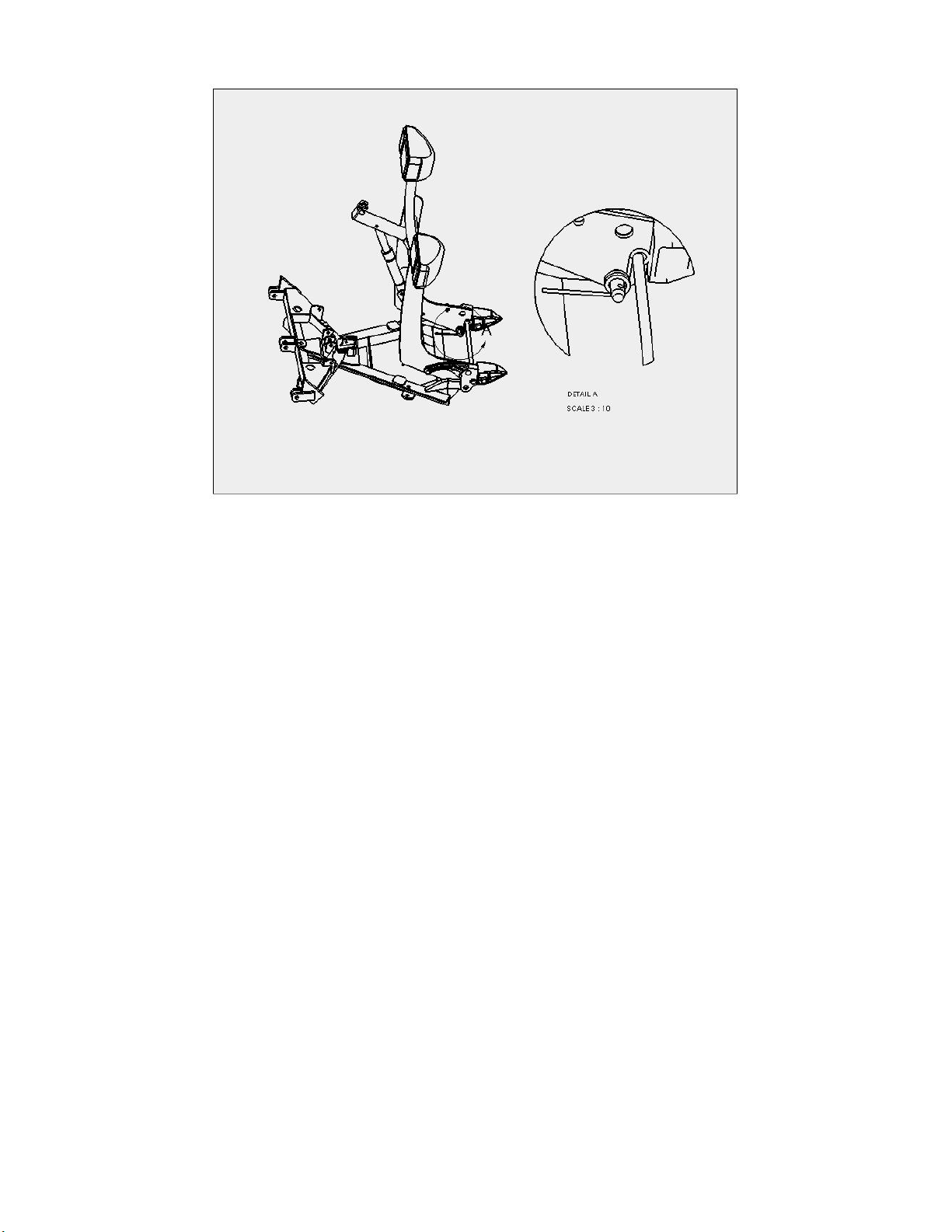
5. With the Front Lift () laying horizontally and facing up, insert Push Frame Pins
through the Front Lift and Push Frame as shown below. Make certain pins also
pass through the coils of the Torsion Springs already mounted to the Front Lift
Spacer Bar (see diagram below). Secure the Push Frame Pins using Lynch Pins
once in place. Rotate the Front Lift up to a vertical orientation. Note the torsion
springs should contact the Push Frame rear support and apply counter-rotational
torque as Front Lift moves upward. Attach the Lift Chain to the Lift Channel to
hold the Front Lift in place and keep from rotating backward.
Page 3 of 6
6. Install the Lift Hose to Hydraulic Pump Unit and Lift Cylinder Elbow. Consult
hydraulic and pump schematics for specific hookup information. Use Teflon pipe
sealant to insure proper hydraulic sealing.
7. Assemble the Right and Left Headlamp Assemblies to the light bar on the Front
Lift using hardware and instructions provided. Do not tighten at this time.
8. Attach the vehicle mounting kit to the vehicle. Consult the vehicle specific
instructions for the required steps.
9. With the vehicle mounting system complete, attach the plow assembly to the
vehicle by driving the vehicle into the plow, insuring that the male alignment
castings are level and the male and female attachment castings are aligned.
Insert the Attachment Pins through the male and female attachment castings and
secure using Lynch Pins. Raise the Jackstand once the pins are fully secured.
10. Install the electrical wiring and harnesses per the schematics and instructions
provided for your specific application.
11. Fill the oil reservoir to within 3/4” inches from the top. Test the operation of the
plow by cycling all cylinders. NOTE – STAND CLEAR OF THE PLOW WHILE
OPERATING. Lower the lift cylinder completely and recheck the reservoir oil
level. Fill to within 3/4” inches from the top if necessary. Replace the Pump

Page 4 of 6
Cover once completed. Attach Safety Chain to Front Lift to transport. Adjust the
headlights per the instructions provided.
12. Check the skidshoe height in relation to the cutting edge. Adjust if necessary.

Page 5 of 6
Mounting Procedure
•Make certain plow attachment is level. Adjust lift chain length if necessary. Line
up the vehicle with the snowplow attachment points and drive straight in until the
snowplow is engaged.
•Insert attachment pins through the push frame and vehicle mounting and secure
using lynch pins.
•Raise the jackstand once the pins are secured.
•Locate the power and controls harnesses on the vehicle and the plow. Remove
the protective covers on each side.
•Connect the controls harness and power cable harness by pushing together.
Position the plugs behind the bumper once connected.
Caution:
Make certain attachment pins are fully engaged and secured with lynch pins and
jackstand is raised prior to operating plow. Failure to do so could cause damage
and/or injury.
Removal Procedure
•Plow should ideally be removed on a hard, level surface. Straighten the power
angle and lower the plow. Lower the jackstand until the foot contacts the floor
surface. Lift slightly on the vehicle bumper if necessary to engage the jack pin.
•Unplug the power and controls harnesses and install protective covers.
•Remove lynch pins and pull attachment pins from the vehicle mount.
•Make certain lift chain is attached. Slowly back vehicle away from plow.
Plow Maintenance
The following simple procedures will help insure years of trouble-free service.
•Monitor hydraulic fluid level regularly. Add when necessary.
•Inspect all hoses, electrical cables, harnesses, and electrical connections on a
regular basis for wear. Replace if necessary.
•Apply dielectric grease to electrical connections prior to and after storage, and
monthly during the snow season.

Page 6 of 6
•Check for leaks from hydraulic fittings and seals.
•Monitor cutting edge and skid shoe wear frequently.
•Check all fasteners regularly for tightness.
•Keep hydraulic cylinder shafts lubricated during storage to prevent corrosion.
•Disengage front lift torsion springs prior to storage.
Table of contents
Other NORTHMAN Automobile Accessories manuals


