manuals.online logo
Brands
  1. Home
  2. •
  3. Brands
  4. •
  5. Dynojet
  6. •
  7. Automobile Accessories
  8. •
  9. Dynojet Power commander V User manual

Dynojet Power commander V User manual

11-014 www.powercommander.com 2013 Arctic Cat 700cc H1 ATV - PCV - 1
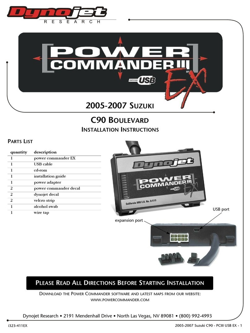
PARTS LIST
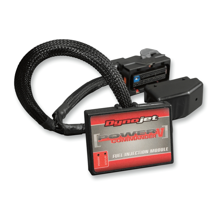
1 Power Commander
1 USB Cable
1 Installation Guide
2 Power Commander Decals
2 Dynojet Decals
1 Posi-tap
2 Velcro strips
1 Alcohol swab
THE LATEST POWER COMMANDER
SOFTWARE AND MAP FILES CAN BE
DOWNLOADED FROM OUR WEB SITE AT:
www.powercommander.com
2013 Arctic Cat 700cc H1 ATV
Installation Instructions
PLEASE READ ALL DIRECTIONS BEFORE STARTING INSTALLATION
THE IGNITION MUST BE TURNED
OFF BEFORE INSTALLATION!
2191 Mendenhall Drive North Las Vegas, NV 89081 (800) 992-4993 www.powercommander.com
11-014 www.powercommander.com 2013 Arctic Cat 700cc H1 ATV - PCV - 2
EXPANSION PORTS 1 & 2
Optional Accessories such as
POD-300 unit or Auto-tune kit
POWER COMMANDER V
INPUT ACCESSORY GUIDE
ACCESSORY INPUTS
Wire connections:
To input wires into the PCV first remove the rubber
plug on the backside of the unit and loosen the
screw for the corresponding input. Using a 22-24
gauge wire strip about 10mm from its end. Push the
wire into the hole of the PCV until is stops and then
tighten the screw. Make sure to reinstall the rubber
plug.
NOTE: If you tin the wires with solder it will make
inserting them easier.
USB CONNECTION
Map - (Input 1 or 2) The PCV has the ability to hold
2 different base maps. You can switch on the
fly between these two base maps when you
hook up a switch to the MAP inputs. You can
use any open/close type switch. The polarity
of the wires is not important. When using the
Autotune kit one position will hold a base map
and the other position will let you activate the
learning mode. When the switch is “CLOSED”
Autotune will be activated. (Set to Switch
Input #1 by default.)
Shifter- (Input 1 or 2) These inputs are for use with the
Dynojet quickshifter. Insert the wires from the
Dynojet quickshifter into the SHIFTER inputs.
The polarity of the wires is not important. (Set
to Switch Input #2 by default.)
Speed- If your application has a speed sensor then
you can tap into the signal side of the sensor
and run a wire into this input. This will allow
you to calculate gear position in the Control
Center Software. Once gear position is setup
you can alter your map based on gear position
and setup gear dependent kill times when
using a quickshifter.
Analog- This input is for a 0-5v signal such as
engine temp, boost, etc. Once this input
is established you can alter your fuel curve
based on this input in the control center
software.
Crank- Do NOT connect anything to this port unless
instructed to do so by Dynojet. It is used to
transfer crank trigger data from one module to
another.
ACCESSORY INPUTS
CRANK
ANALOG
SPEED
INPUT 1 (Grnd)
INPUT 1
INPUT 2 (Grnd)
INPUT 2
11-014 www.powercommander.com 2013 Arctic Cat 700cc H1 ATV - PCV - 3
1 Remove the seat and left hand side panel shown in Figure A.
2 Remove the storage cover shown in Figure B and the storage bin.
3 Loosen the clamp from the throttle body and remove the air snorkel from the
throttle body.
4 To make the fuel injector more accessible, lift the snorkel/airbox upward away
from the top of the engine.
5 Remove the two screws securing the tool kit to expose the battery.
6 Using the supplied Velcro, secure the PCV under the seat at the location
shown in Figure C.
Clean both surfaces with the supplied alcohol swab before attaching the
Velcro.
7 Route the PCV wiring harness under the frame spar toward the front of the
machine.
8 Attach the ground wire from the PCV to the negative (-) terminal of the battery.
FIG.A
FIG.B
Remove
FIG.C
Ground
Snorkel
PCV
Remove
Remove
11-014 www.powercommander.com 2013 Arctic Cat 700cc H1 ATV - PCV - 4
9 Disconnect the stock wiring harness from the fuel injector (Fig. D).
10 Plug the PCV wiring harness in-line of the fuel injector and the stock wiring
harness.
11 Locate the Throttle Position Sensor (TPS) on the
left hand side of the throttle body.
12 Using the supplied posi-tap, attach the GREY wire
from the PCV to the stock GREEN/BLACK wire
from the TPS.
13 Replace the storage bin, cover, tool kit, side panel,
and seat.
FIG.E
TPS
Posi-tap
FIG.D
Unplug

Other manuals for Power commander V

95

Other Dynojet Automobile Accessories manuals

Dynojet Power commander V User manual

Dynojet

Dynojet Power commander V User manual

Dynojet POWER COMMANDER III USB EX User manual

Dynojet

Dynojet POWER COMMANDER III USB EX User manual

Dynojet Power commander V User manual

Dynojet

Dynojet Power commander V User manual

Dynojet Power commander V User manual

Dynojet

Dynojet Power commander V User manual

Dynojet power commander III User manual

Dynojet

Dynojet power commander III User manual

Dynojet power commander III User manual

Dynojet

Dynojet power commander III User manual

Dynojet Power Commander III Service manual

Dynojet

Dynojet Power Commander III Service manual

Dynojet Power Vision User manual

Dynojet

Dynojet Power Vision User manual

Dynojet Power commander V User manual

Dynojet

Dynojet Power commander V User manual

Dynojet POWER VISION 3 User manual

Dynojet

Dynojet POWER VISION 3 User manual

Dynojet Power commander V Quick start guide

Dynojet

Dynojet Power commander V Quick start guide

Dynojet Power commander V User manual

Dynojet

Dynojet Power commander V User manual

Dynojet Power commander V Service manual

Dynojet

Dynojet Power commander V Service manual

Dynojet Power commander V User manual

Dynojet

Dynojet Power commander V User manual

Dynojet POWER VISION 3 User manual

Dynojet

Dynojet POWER VISION 3 User manual

Dynojet Auto Tune User manual

Dynojet

Dynojet Auto Tune User manual

Dynojet power commander III User manual

Dynojet

Dynojet power commander III User manual

Dynojet Power Commander III USB User manual

Dynojet

Dynojet Power Commander III USB User manual

Dynojet Power commander V User manual

Dynojet

Dynojet Power commander V User manual

Dynojet POWER VISION PV3-2504C User manual

Dynojet

Dynojet POWER VISION PV3-2504C User manual

Dynojet Power commander V User manual

Dynojet

Dynojet Power commander V User manual

Dynojet POWER VISION PV3-25-09 User manual

Dynojet

Dynojet POWER VISION PV3-25-09 User manual

Dynojet Power commander V User manual

Dynojet

Dynojet Power commander V User manual

Dynojet Power Commander III User manual

Dynojet

Dynojet Power Commander III User manual

Popular Automobile Accessories manuals by other brands

Seizmik 08072 Installation & operation manual

Seizmik

Seizmik 08072 Installation & operation manual

GATmatic GT510 user manual

GATmatic

GATmatic GT510 user manual

weBoost DRIVE 3G-S Quick install guide

weBoost

weBoost DRIVE 3G-S Quick install guide

Whispbar K130W Fitting instructions

Whispbar

Whispbar K130W Fitting instructions

MAcarbon Ferrari 360 Map Carbon Light installation instructions

MAcarbon

MAcarbon Ferrari 360 Map Carbon Light installation instructions

AUTOCHAIR SMART TRANSFER T-MPL User & installation manual

AUTOCHAIR

AUTOCHAIR SMART TRANSFER T-MPL User & installation manual

Honeywell VX3Plus reference guide

Honeywell

Honeywell VX3Plus reference guide

Safe Fleet PRIME DESIGN VCR-TC21B manual

Safe Fleet

Safe Fleet PRIME DESIGN VCR-TC21B manual

POOL-LINE 110205 Assembly instructions

POOL-LINE

POOL-LINE 110205 Assembly instructions

Lippert Components Happijack FT-DR2 quick start guide

Lippert Components

Lippert Components Happijack FT-DR2 quick start guide

Atera Signo 044 049 User information

Atera

Atera Signo 044 049 User information

Thule 110001 Series instructions

Thule

Thule 110001 Series instructions

Hamron 619-654 operating instructions

Hamron

Hamron 619-654 operating instructions

Well Well instruction manual

Well

Well Well instruction manual

Whispbar K720W Fitting instructions

Whispbar

Whispbar K720W Fitting instructions

Kuda-Phonebase 052060 Installation instruction

Kuda-Phonebase

Kuda-Phonebase 052060 Installation instruction

TAUBENREUTHER 16-9520 manual

TAUBENREUTHER

TAUBENREUTHER 16-9520 manual

DVB SPEC Series installation manual

DVB

DVB SPEC Series installation manual

manuals.online logo
manuals.online logoBrands
  • About & Mission
  • Contact us
  • Privacy Policy
  • Terms and Conditions

Copyright 2025 Manuals.Online. All Rights Reserved.