NORTHROP GRUMMAN Sperry Marine NAVIGAT X MK 2 User manual

Sperry Marine
Head Office and Freight: Woltmanstrasse 19, D-20097 Hamburg, Germany
Correspondence Address: P.O. Box 10 47 09, D-20032 Hamburg, Germany
056341
User, Technical and Service Manual
NAVIGAT X MK 2
Digital Gyrocompass System
Rev. AA, 07 May 2004

056341 Rev. AA NAVIGAT X Mk 2
Copyright ©
Northrop Grumman Sperry Marine, Hamburg, 2004
This document contains proprietary information of
Northrop Grumman Sperry Marine, Hamburg, Germany.
Any reproduction or publication of this document or any portions thereof without the prior
written consent of Sperry Marine is expressly prohibited.
Subject to alteration without notice.
Revision Record
Rev. Date Remarks
AA 07 May 2004 initial release

NAVIGAT X Mk 2 056341 Rev. AA
i
Contents
Safety Precautions
1Description
1.1 Design and Main Features...................................................................................1–1
1.2 Data and Signal Interfaces ..................................................................................1–2
1.3 Technical Data ......................................................................................................1–3
2Operation
2.1 Operating Conditions...........................................................................................2–1
2.2 Power-up Sequence.............................................................................................2–1
2.3 Display and Control Elements.............................................................................2–2
2.3.1 Control and Display Unit ..........................................................................2–2
2.3.2 External Control Devices ..........................................................................2–2
2.4 Selecting the Heading Reference........................................................................2–3
2.4.1 Selection from the Control and Display Unit..........................................2–3
2.4.2 Selection from the Compass Monitor .....................................................2–3
2.4.3 Selection via external selector switch.....................................................2–3
2.5 Adjusting the Display Brightness .......................................................................2–4
2.6 Acknowledging Alarms / Muting the Audible Alarm ........................................2–4
2.7 Optional Functions...............................................................................................2–4
2.7.1 Acknowledging Alarms Remotely ...........................................................2–4
2.8 Operating Menu ...................................................................................................2–5
2.8.1 Entering / Quitting the Main Menu..........................................................2–5
2.8.2 Navigating the Menu ................................................................................2–5
2.8.3 Selecting Parameter Settings ..................................................................2–6
2.8.4 Editing Parameter Values.........................................................................2–6
2.9 Display Data Menu...............................................................................................2–7
2.10 Manual Settings Menu ........................................................................................2–8
2.10.1 Manual Settings – Overview ....................................................................2–8
2.10.2 Manual Settings – Parameters.................................................................2–9
Speed/Latitude ..................................................................................2–9
Hdg. Diff. Alarm ..............................................................................2–10
Magnetic Variation .........................................................................2–11
North Speed Error Correction .......................................................2–12
Settings NAVIPRINT .......................................................................2–13
Settings RoT / Time Const. RoT ....................................................2–14
2.11 User Setup ..........................................................................................................2–15
2.11.1 User Setup – Overview...........................................................................2–15
2.11.2 User Setup – Parameters........................................................................2–16
Date/Time ........................................................................................2–16
Software Version ............................................................................2–17
Magnetic Compass Calibration Table ...........................................2–17

056341 Rev. AA NAVIGAT X Mk 2
ii
3ErrorsandAlarms
3.1 Alarm Indication .................................................................................................. 3–1
3.1.1 Audible Alarm Indication ......................................................................... 3–1
Invalid Function ................................................................................ 3–1
System Alarm ................................................................................... 3–1
3.1.2 Visual Alarm Indication............................................................................ 3–1
3.1.3 Acknowledging Alarms / Muting the Audible Alarm............................. 3–1
3.2 Error Messages.................................................................................................... 3–2
3.3 Service Info Menu (Service Setup 2).................................................................. 3–3
3.3.1 Service Setup 2 – Access Code ............................................................... 3–3
3.3.2 Service Setup 2 – Overview..................................................................... 3–3
3.3.3 Service Setup 2 – Parameters.................................................................. 3–4
Gyrosphere Data .............................................................................. 3–4
Op. Time Counter ............................................................................. 3–4
Data List ............................................................................................ 3–4
Error List ........................................................................................... 3–4
Reset MK 2 ........................................................................................ 3–4
4 Preventive Maintenance
4.1 Maintenance Specifications................................................................................ 4–1
4.1.1 Gyrosphere Maintenance ........................................................................ 4–1
4.1.2 Five-Year Maintenance ............................................................................ 4–1
4.1.3 System Software Updates ....................................................................... 4–1
4.2 Maintenance by Shipboard Personnel............................................................... 4–2
4.2.1 Protecting the Gyrosphere from Low Ambient Temperatures............. 4–2
4.2.2 Removing the gyrosphere container from the compass housing........ 4–3
4.2.3 Re-installing the gyrosphere container in the compass housing......... 4–5
4.2.4 Power-up Function Test ........................................................................... 4–7
4.3 Maintenance by Service Personnel.................................................................... 4–9
4.3.1 Gyrosphere Installation and Service....................................................... 4–9
4.3.2 Updating the System Software ............................................................... 4–9
5 Installation
5.1 Installing the Compass Housing......................................................................... 5–1
5.2 Electrical Installation ........................................................................................... 5–2
5.3 Gyrosphere Installation....................................................................................... 5–2
5.4 Initial System Configuration ............................................................................... 5–3
5.4.1 Alignment Error Correction ..................................................................... 5–5
5.4.2 Magnetic Compass Calibration ............................................................... 5–6

NAVIGAT X Mk 2 056341 Rev. AA
iii
6 System Configuration
6.1 Configuration Menu (Service Setup 1)...............................................................6–1
6.1.1 Service Setup 1 – Access Code................................................................6–1
6.1.2 Service-Setup 1 – Overview .....................................................................6–2
6.1.3 Service Setup 1 – Parameters ..................................................................6–5
Interface I/O .......................................................................................6–5
Mag. Hdg. Inp. ...........................................................................6–5
Speed Input ...............................................................................6–5
Pos. Input ...................................................................................6–6
Sens. D.M. Outp. .......................................................................6–6
S/Fast M. Outp. ..........................................................................6–7
Magn. Variation .........................................................................6–7
NMEA Superfast ........................................................................6–8
TxD NMEA Fast .........................................................................6–8
Sens Data 2 ................................................................................6–8
Analog ROT Outp. ............................................................................6–9
Sc. Factor ...................................................................................6–9
Zero Offset .................................................................................6–9
Protocol Type ....................................................................................6–9
System Type .....................................................................................6–9
System .......................................................................................6–9
Hdg. Sel. ...................................................................................6–10
Align Err. Corr. ................................................................................6–10
Shaft Cor. Angle .............................................................................6–10
Gen. Alarm Setup ...........................................................................6–10
Name Of Gyro .................................................................................6–11
Test Mode .......................................................................................6–11
Rate of Turn .............................................................................6–11
Change Settings ......................................................................6–11
Heading Value .........................................................................6–11
6.2 Factory Settings Menu (Technical Pages)........................................................6–12
6.2.1 Technical Pages – Access Code .............................................................6–12
6.2.2 Technical Pages – Overview ..................................................................6–12
6.2.3 Technical Pages – Parameters ...............................................................6–13
Software Version ............................................................................6–13
Update Software .............................................................................6–13
Correction Val. ................................................................................6–13
7 Troubleshooting / Corrective Maintenance
7.1 Troubleshooting Instructions..............................................................................7–1
7.2 Parts Location on Main PCB................................................................................7–1
7.2.1 Diagnostic LED indicators ........................................................................7–1
7.2.2 Connectors, Socketed ICs, Test Resistor, Potentiometers.....................7–3

056341 Rev. AA NAVIGAT X Mk 2
iv
8 Gyroshpere Installation and Service
8.1 Safety Notes......................................................................................................... 8–1
8.1.1 Material Specification, Risk and Safety Information ............................. 8–1
8.2 Gyrosphere Handling and Storage Instructions ............................................... 8–2
8.3 Installation of the Gyrosphere ............................................................................ 8–3
8.3.1 Installing the Gyrosphere in the Gyrosphere Container ....................... 8–3
8.3.2 Installing the gyrosphere container in the compass housing .............. 8–8
8.3.3 Power-up Function Test ......................................................................... 8–10
8.4 Gyrosphere Maintenance Procedures ............................................................. 8–12
8.4.1 Removing the gyrosphere container from the compass housing...... 8–12
8.4.2 Removing the gyrosphere from the gyrosphere container ................ 8–14
8.4.3 Preparing the gyrosphere for re-installation........................................ 8–18
8.4.4 Exchanging the gyrosphere................................................................... 8–19
App. A Setup Tables
App. BDrawings

NAVIGAT X Mk 2 056341 Rev. AA
v
Safety Precautions
The following safety notice conventions are followed throughout this manual:
A Warning contains an operating or maintenance procedure, practice, condition, statement,
etc., which, if not strictly observed, could result in injury or death of personnel.
Special warning symbols are used in this manual to indicate
Danger from toxic substances,
Danger of electrical shock.
A Caution contains an operating or maintenance procedure, practice, condicion, statement,
etc., which, if not strictly observed, could result in damage to, or destruction of equipment.
Special caution symbols are used in this manual to indicate
Sensitivity of components to electric discharge.
A Note contains an essential operating or maintenance procedure, condition or statement
which is considered importnt enough to be highlighted.
Warning
Careless or improper use of this system may result in vessel damage and/or
SERIOUS INJURY OR DEATH.
Before using this system, operators must be appropriately trained and familiar
with the warnings, safety instructions contained in this manual and on system
components.
Always keep system manuals in a well-known, readily available location.
Caution
Never exceed specified system power or environmental limits.
Only trained Sperry Marine service personnel is authorized to provide service
or make repairs to this system.
Never install unauthorized additional components into this system
Never make unauthorized modifications to this system

056341 Rev. AA NAVIGAT X Mk 2
vi

NAVIGAT X Mk 2 056341 Rev. AA
1: Description Page 1-1
1 Description
1.1 Design and Main Features
The NAVIGAT X MK 2 is a microprocessor controlled gyrocompass system with
integrated automatic North speed error correction.
The single unit design with a polyurethane hard foam housing allows the gyro-
compass to be installed on any bridge. If required, an optional remote operat-
ing unit may be installed.
The unique method of supporting the gyrosphere by means of mere buoyancy
ensures North stabilization during short power failures. E.g., after a three
minute loss of power, no more than two degrees of deviation may be expected.
Once power has been restored, the gyrocompass will return quickly to the cor-
rect heading. The combined effects of the twin rotors and the liquid damping
system virtually eliminate latitude error.
Heading is measured as a 13-bit absolute value with a digital shaft encoder. The
high-speed follow-up system (follow-up speed up to 100°/s) ensures that accu-
rate heading and rate of turn data is provided under all operating conditions.
Integrated monitoring of the supply powers, gyroscope current and the follow-
up system ensure secure and trouble-free operation.

056341 Rev. AA NAVIGAT X Mk 2
Page 1-2 1: Description
1.2 Data and Signal Interfaces
The NAVIGAT X MK 2 provides input interfaces for a magnetic compass (flux-
gate sensor or electronic compass), speed log and position receiver.
The system provides four serial data outputs to analogue or digital repeaters
(including short-circuit-proof 24 VDC repeater power supply), two RS422 sen-
sor data outputs, a Fast output interface (reduced dataset) and a Superfast out-
put interface (adjustable baudrate, max. 38400 baud).
Furthermore, a Furuno AD10 heading output, a 6 step/° heading output, and an
analogue rate of turn output are provided. One sensor data output may be con-
figured to produce a graphical heading printout in conjunction with the nav.
data printer NAVIPRINT.
Fig. 1–1:
NAVIGAT X MK 2 data
and signal interfaces
The NAVIGAT X MK 2 may also be used as part of a component multicompass
system in conjunction with the Compass Monitor NAVITWIN III and a Switch-
Over Unit. In such a system, the Compass Monitor acts as the main heading
source selector and controls distribution of the compasses' output signals via
the Switch-Over Unit.
Magnetic
Compass
Position Receiver
Speed Log
Status Signals In
ROT
Serial Repeaters
Equipment using
serial input
Equipment using
6 step/˚ input
Equipment using
Furuno AD10 input
Analogue
R.o.T.
Indicators
Nav. Data
Printer
Status Signals Out

NAVIGAT X Mk 2 056341 Rev. AA
1: Description Page 1-3
1.3 Technical Data
heading display ........................................................... 4-digit
max. follow-up speed.................................................. 100°/s
mean settling time....................................................... < 3 h
freedom of roll and pitch ............................................ ±40°
Accuracies
lin. mean settle point error .............................................. ≤ 0.1° sec lat
static error ............................................................................ ≤ 0.1° sec lat
dynamic error...................................................................... ≤ 0.4° sec lat
deviation after 3 min. power interruption ................. < 2°
Environmental Requirements
ambient temperature, operation ................................ -10 – +55 °C
ambient temperature, storage.................................... -25 – +70 °C
(w/o supporting fluid)
protection grade .......................................................... IP 23 to DIN 40050
Environmental Requirements and EMC .................. in accordance w. IEC 60945
Power Supply
supply voltages............................................................ main 24 VDC (18 - 36 V),
backup 24 VDC (18-36 V);
including automatic switch-
over to 24 V backup supply
in accordance with GMDSS
rules for INMARSAT/SES
terminals
max. ripple content ..................................................... ±4 Vpp; extreme values
may not exceed 36 V or fall
below 18V
Power Consumption
start-up ......................................................................... 80 W
operation ...................................................................... 45 W
each analogue repeater .............................................. 7 W
each digital repeater.................................................... 7 W
Dimensions and Weight
width................................................... 404 mm
height ................................................. 520 mm
depth .................................................. 420 mm
weight.................................................25 kg
404
520
420420

056341 Rev. AA NAVIGAT X Mk 2
Page 1-4 1: Description
Data Outputs
repeater (4x NMEA)..................................................... gyrocompass heading
magnetic compass heading
rate of turn
heading reference status
4x supply 24 VDC,
max. 7 W each
sensor data (2 x RS422) .............................................. gyrocompass heading
magnetic compass heading
rate of turn
position
speed
heading reference status
RS 422 Fast................................................................... gyrocompass heading
magnetic compass heading
rate of turn
heading reference status
RS 422 SuperFast ........................................................ gyrocompass heading
magnetic compass heading
rate of turn
heading reference status
6 step/° output.............................................................. act. heading
supply 24 VDC, max. 18 W
AD10 output ................................................................. gyrocompass heading
rate of turn, analogue.................................................. ±0.1–999.9 mV/°/min;
max. 10V, 10 mA
nav. data printer........................................................... graph: act. heading;
text: date, time, heading
reference, steering mode,
speed, position
Alarm and Status Outputs
potential-free contact closures,
max. 30W, 125V/1A each............................................. power failure / general de-
vice error
heading difference alarm
Data and Signal Inputs
magnetic heading........................................................ NMEA 0183
or PLATH-format
or NAVITWIN III
or NAVIPILOT
position......................................................................... NMEA 0183
speed ............................................................................ NMEA 0183
or 200 pulses/nm
steering mode (auto/man) .......................................... sel. switch status
heading reference ext. (gyro/mag)............................. sel. switch status
ext. alarm acknowledge (mute) .................................. sel. switch status

NAVIGAT X Mk 2 056341 Rev. AA
2: Operation Page 2-1
2 Operation
2.1 Operating Conditions
The permitted ambient temperature for the operation of the gyrocompass sys-
tem is -10 – +55 °C.
When the ambient temperature at the gyrocompass’ location falls below -10 °C
while the compass is in operation or when the ambient temperature falls below
0°C while the compass is not in operation, the gyrosphere container must be re-
moved from the compass housing and stored in a place where the ambient
temperature will not fall below 0 °C.
If no storage place is available where the ambient temperature will not fall be-
low 0 °C, the gyrosphere must be removed from the gyrosphere container to
prevent possible damage by frozen supporting fluid.
2.2 Power-up Sequence
The NAVIGAT X MK 2 is not equipped with a power switch. The system powers
up as soon as the supply power is applied. No special procedures need to be
followed to power the system up or down.
Warning
The NAVIGAT X MK 2 may no longer be operated when the ambient tempera-
ture at the gyrocompass’ location falls below -10 °C.
Caution
The gyrosphere may be removed from the gyrospere container by authorized
service personnel only.
To power up the NAVIGAT X MK 2:
Energize the system at the vessel’s switch and
fuse unit.
A startup message is displayed and the initial
selftest is executed.
The heading display screen is shown, which dis-
plays the heading data from the available com-
passes and the heading difference alarm
threshold.
The system is now operational.
SPERRY MARINE
NAVIGAT X MK 2
>F1
MK2 HEADING
GYRO 1 271.2°
F2 MAGN.C. 270.9°
DIFF G1/M 5° ü
Warning
After a power-up from cold, the NAVIGAT X MK 2 requires a settling time of
three hours before reliable heading data is available.
Power up the system at least three hours before leaving harbour.
Power down the system during long docking periods only.

056341 Rev. AA NAVIGAT X Mk 2
Page 2-2 2: Operation
2.3 Display and Control Elements
2.3.1 Control and Display Unit
The NAVIGAT X MK 2 is operated from the integrated Control and Display Unit.
The control keys provide access to the compass’ multilevel display and operat-
ing menu. An integrated alarm buzzer provides audible alarm indication.
Fig. 2–1:
Control and Display Unit
2.3.2 External Control Devices
Depending on the installation, external devices may be present which control
certain functions of the NAVIGAT X MK 2:
• An additional Control and Display Unit may be used to operate the gyro-
compass from a remote location.
• A Compass Monitor NAVITWIN III may be used to select the heading
source and control data distribution to repeaters and other equipment.
• An external selector switch may be used to select between the Gyro and
Magnetic heading sources.
• A central alarm monitoring device may be used to display and acknowl-
edge gyrocompass alarms.
Control Keys
MENU
(Up)
(Down)
DIM –
DIM +
F1
F2
F3
RESET
ENTER
SHIFT
functions:
direct
functions:
LCD Display Screen
4 x 20 characters, alphanumerical

NAVIGAT X Mk 2 056341 Rev. AA
2: Operation Page 2-3
2.4 Selecting the Heading Reference
The operator may select one of the available heading sources as the heading
reference for the devices connected to the gyrocompass system (e.g. autopilot,
repeaters etc.). The selected heading reference is indicated by an arrow symbol
(>) in front of the corresponding heading value in the display.
2.4.1 Selection from the Control and Display Unit
2.4.2 Selection from the Compass Monitor
In multicompass systems with the Compass Monitor NAVITWIN III, the Com-
pass Monitor is usually configured as the main heading selector unit.
2.4.3 Selection via external selector switch
Use the external selector switch to select the heading reference.
In systems equipped with an ext. selector switch, heading selection via the Con-
trol and Display Unit(s) or the Compass Monitor is disabled.
Note
Heading reference selection is permitted in manual steering mode only.
In autopilot steering mode, the heading reference cannot be changed.
While the heading display screen is shown:
Press keys simultaneously to select the Gyro.
Press keys simultaneously to select the magnetic compass.
At the Compass Monitor, press key to select Gyro 1.
At the Compass Monitor, press key to select Gyro 2.
At the Compass Monitor, press key to select magnetic compass.
Note
In systems equipped with the Compass Monitor, heading selection via the com-
passes’ Control and Display Unit(s) is disabled.

056341 Rev. AA NAVIGAT X Mk 2
Page 2-4 2: Operation
2.5 Adjusting the Display Brightness
2.6 Acknowledging Alarms / Muting the Audible Alarm
2.7 Optional Functions
The following functions are available only if the gyrocompass system is
equipped with the respective optional controls.
2.7.1 Acknowledging Alarms Remotely
On alarm, acknowlede the alarm from a remote device (e.g. a central alarm
panel). The audible alarm is muted. The alarm message will remain on the dis-
play screen until the alarm is confirmed at the operating unit.
Press key to increase the display brightness.
Press key to reduce the display brightness.
On alarm, press keys to acknowledge the alarm and clear the
alarm message from the display screen. The audible alarm is
muted simultaneously.
On alarm, press keys to mute the audible alarm.
The alarm message will remain on the display screen until the
alarm is acknowledged at the operating unit.
Note
When the cause of an alarm is eliminated, a pending alarm message is cleared
from the display and the audible alarm is muted automatically.
When an alarm has been confirmed, the ext. alarm status output will remain ac-
tive until the cause of the alarm is eliminated.

NAVIGAT X Mk 2 056341 Rev. AA
2: Operation Page 2-5
2.8 Operating Menu
The data display screens and the manual settings, user and service setup
modes are accessed via a multilevel operating menu.
2.8.1 Entering / Quitting the Main Menu
2.8.2 Navigating the Menu
or
From the heading display screen,
press key to go to the main menu
screen.
From the main menu screen, press
key to return to the heading display
screen.
>F1
MK2 HEADING
GYRO 1 271.2°
F2 MAGN.C. 270.9°
DIFF G1/M 5° ü
MAIN MENU û
F1 DISPLAY DATA
F2 MANUAL SETTINGS
F3 SETUP MENU
a c/b
Press keys to enter a sub-menu
Press key to return to the next higher menu level.
/
Press key to go to the next/previous screen on the same menu
level.
ûû
ü
b
a
c
dbda dc
û
û
ü
ü
û
û
ü
ü
û
û
ü
ü

056341 Rev. AA NAVIGAT X Mk 2
Page 2-6 2: Operation
2.8.3 Selecting Parameter Settings
In a number of sub-menus, parameters are set by selecting one out of several
options. Flashing up/down arrow symbols indicate that the operator is expected
to select the required setting.
2.8.4 Editing Parameter Values
In a number of sub-menus, parameters are set by editing a numerical value. A
flashing box symbol indicates that the operator is expected to edit a value.
When flashing arrows are shown:
/
Press key to scroll up/down through
available options.
Press keys to confirm input and go to
next line.
MAN.SETTINGS
SPEED MODE: AUTO
POSIT MODE: AUTO
ý
When the flashing box is shown:
/
Press key to increase/decrease the
value at the cursor position up/down
through available options.
/
Press keys to move the cursor to the
next/previous position.
Press keys to confirm input and go to
next line.
Press keys to clear the input (value is
set to zero).
MAN.SETTINGS
MAN SPEED: **.* Kt
MAN LAT: **:**.** N

NAVIGAT X Mk 2 056341 Rev. AA
2: Operation Page 2-7
2.9 Display Data Menu
The Display Data menu provides access to the data display screens. The se-
lected display screen remains active until the user selects a different screen or
quits the display data menu.
Fig. 2–2: Display data
menu screens
DISPLAY DATA GYRO 1
HEADING TRUE 271.3°
ROT 1.2 °/MIN
CORR. ON 0.2°ü
Gyrocompass data
- gyrocompass heading
- rate of turn
- correction status (on/off), act. value
DISPLAY DATA GYRO 1û
HEADING MAGN 270.9°
MAGN.VAR. 2.3° E
ü
Magnetic compass data (if available)
- magnetic compass heading
- magnetic variation
DISPLAY DATA GYRO 1û
POSITION AUTO
LAT 44.09.46 N
LON 023.54.21 E ü
Position data (if available)
- position mode (auto/man)
- latitude
- longitude
DISPLAY DATA GYRO 1û
SPEED AUTO
12.3 kt
ü
Speed (if available)
- speed mode (auto/man)
- actual speed
DISPLAY DATA GYRO 1û
DATE 23.01.99
TIME 12.34
ü
Date / T ime
- current date
- current time
bc
bc
bc
bc
c

056341 Rev. AA NAVIGAT X Mk 2
Page 2-8 2: Operation
2.10 Manual Settings Menu
The Manual Settings Menu contains operational settings which may require to
be altered by the operator during normal operation.
2.10.1 Manual Settings – Overview
Fig. 2–3: The Manual
Settings Menu
MAN.SETTINGS GYRO 1û
F1 NORTH SP.ERR.CORR
F2 SET. NAVIPRINT
F3 SETTINGS ROT
MAN.SETTINGS GYRO 1
F1 SPEED/LATITUDE
F2 HDG DIFF.ALARM
F3 MAG. VARIATION ü
SPEED/LATITUDE
HDG. DIFF. ALARM
MAGNETIC VARIATION
NORTH SP. ERR. CORR
SET. NAVIPRINT
SETTINGS ROT
SPEED/LAT MODE
BETWEEN
MODE
ON
OFF
NAVIPRINT
TIME CONST. ROT
PAP. SPEED
HDG
ON
damping time constant: 0.0 – 10.0 s
60 mm
±30˚
OFF
150 mm
±180˚
600 mm
AUTO
SPEED MODE
GY1 / M
AUTO
AUTO
POSIT MODE
man. lat. value: 99:99.99 N – 99:99.99 S
SPEED/LAT SET
man. speed value: 0.0 – 99.9 kts.
speed/latitude input settings
heading difference alarm threshol
d
mag. variation input settings
north speed error correction
nav. data printer settings
rate of turn time constan
t
MAN
MAN
MAN
OFF
alarm threshold: 0 – 99˚
man. variation value: 99.9˚ W – 99.9˚ E
bc
Table of contents
Other NORTHROP GRUMMAN Measuring Instrument manuals

NORTHROP GRUMMAN
NORTHROP GRUMMAN IKA-012-QTG User manual
NORTHROP GRUMMAN
NORTHROP GRUMMAN NORMARC 7710 NAV User manual

NORTHROP GRUMMAN
NORTHROP GRUMMAN Patara EPL-016-QTG User manual

NORTHROP GRUMMAN
NORTHROP GRUMMAN Iklwa II TEM00 User manual
NORTHROP GRUMMAN
NORTHROP GRUMMAN Patara II Manual
NORTHROP GRUMMAN
NORTHROP GRUMMAN Patara I User manual
NORTHROP GRUMMAN
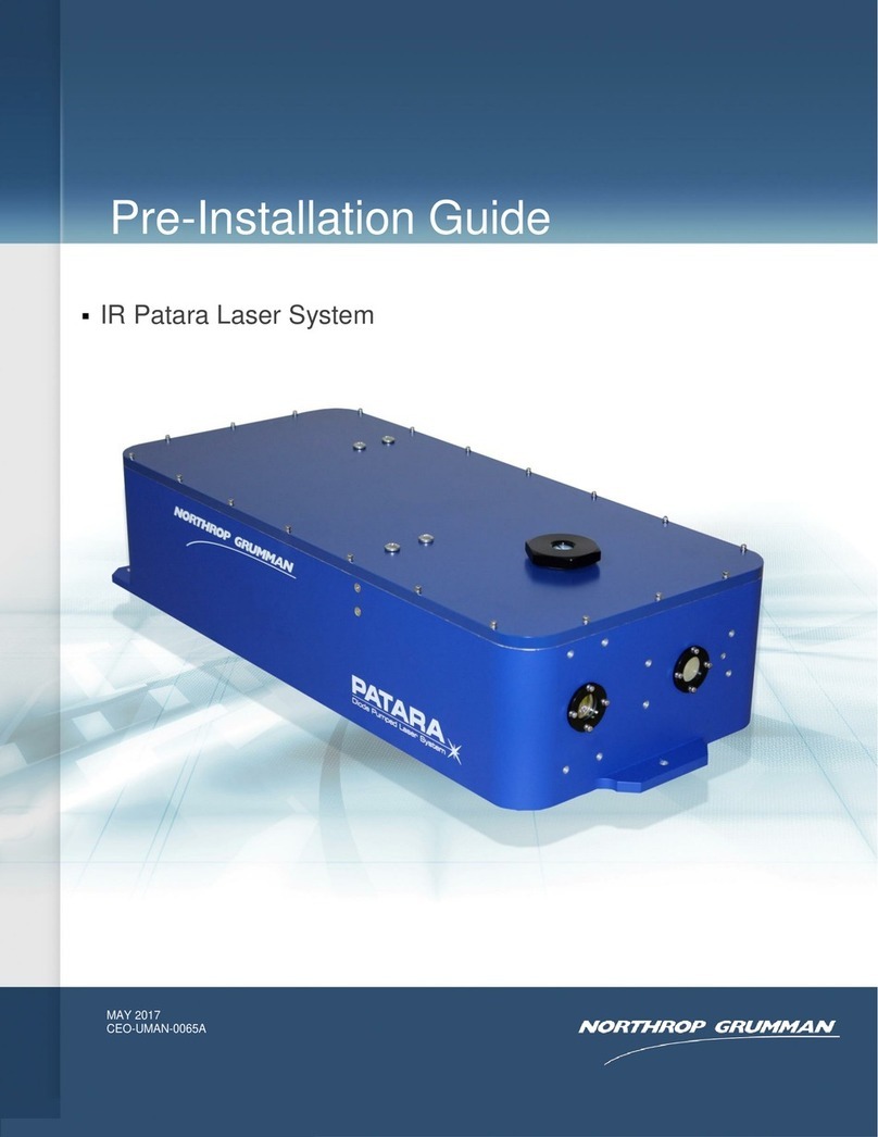
NORTHROP GRUMMAN IR Patara Laser System User manual
