NORTHROP GRUMMAN Iklwa II TEM00 User manual

uble Shooting Guid
SVC-UMAN-0007 C
JANUARY 2019
Service Manual
Iklwa II TEM00 Green Laser
Patara II TEM00 Green laser

© 2019 Cutting Edge Optronics, Inc. ii Patara II and Iklwa II Service Manual
Worldwide Technical Support and Product Information
http://www.northropgrumman.com/BusinessVentures/CEO/Pages/Service.aspx
http://www.ngceoservice.com/ (Knowledge Center)
Hours: 8:00 a.m. to 5:00 p.m., Central time*
Technical Support: (636) 916-4900 (follow prompts for department directory)
Cutting Edge Optronics Headquarters
20 Point West Blvd. St. Charles, MO 63301 USA
Sales Support: (636) 916-4900 (follow prompts for department directory)
*After office hours, please leave a voice mail message. Outside North America, contact an NG sales office or distributor; see the NG website
for a list of offices.

© 2019 Cutting Edge Optronics, Inc. iii Patara II and Iklwa II Service Manual
Important Information
Copyright
Under the copyright laws, this publication may not be reproduced or transmitted in any form, electronic or mechanical,
including photocopying, recording, storing in an information retrieval system, or translating, in whole or in part, without the
prior written consent of Northrop Grumman Corporation.
Patents
Northrop Grumman Corporation products are covered by U.S. and foreign patents, issued and pending. Information in this
publication supersedes that in all previously published material. Specifications and price change privileges reserved.

© 2019 Cutting Edge Optronics, Inc. iv Patara II and Iklwa II Service Manual
Safety Information
Product End-of-Life Handling
NG is committed to protecting the environment. In accordance with the Waste Electrical
and Electronic Equipment directive (WEEE) and Restriction of Hazardous Substances in
the European Union (RoHS EU) directives, NG accepts the return of our products for
disposal. When you are ready to reclaim the instrument, you must properly transfer it
according to local regulations concerning WEEE equipment. Contact NG or your local
distributor for shipping instructions. Please package the products as directed for a return
for repair.
ROC ROHS Declaration
In accordance with the Clause 6.2 of Marking for Control of Pollution Caused by
Electronic Information Products (SJ/T11364:2006) for Measures for the
Administration on Pollution Control of Electronic Information Products No. 39,
Order of the Ministry of Information Industry of the Peoples Republic of China,
NG includes the following translation about our products.
© 2019 Cutting Edge Optronics, Inc. v Patara II and Iklwa II Service Manual
Conventions
The following conventions appear in this manual:
This icon denotes a caution or a warning, which advise you of precautions to
take to avoid injury, data loss, or a system crash.
Initial Capped
The first letter in uppercase refers to menu options, e.g., Phase Delay, Pulse
Width.
CAPS
Front-panel buttons, knobs, and connectors appear in all uppercase letters, e.g.,
MENU, CURRENT.
The symbol separates a sequence of button pushes, e.g., MENU
CHANNEL SETUP PULSE WIDTH means that you push the MENU
button, then push the CHANNEL SETUP soft key, and then push the PULSE
WIDTH soft key.
italic
Italic text denotes references to other resources that may be helpful to you or to
bring attention to important information.
This icon denotes a note, which alerts you to important information.
I
O
Power Switch Position Symbols
I = On O = Off
The following conventions may appear on the product:
DANGER
An injury hazard immediately accessible as you read the marking.
WARNING
A hazard not immediately accessible as you read the marking.
CAUTION
A hazard to property including the product.
ESD: Handle Appropriately

© 2019 Cutting Edge Optronics, Inc. vi Patara II and Iklwa II Service Manual
Laser Emission: Use caution.
Shock Hazard: Use caution.
Caution: Risk of danger. Refer to manual.
Chassis Ground
Additional Resources
NG is committed to providing support for all customers. Installation how-to
videos, technical manuals, and descriptions and specifications of products can be
found by visiting http://www.ngceoservice.com.

© 2019 Cutting Edge Optronics, Inc. vii Patara II and Iklwa II Service Manual
Table of Contents
Chapter 1: General Instructions 1
Safety 1
Cleanliness 3
Tools, Equipment, and Materials 3
Alignment Reference, Test Set-up and Laser Layout 4
Fastener Torque and Tack Locations 6
Servicing the Laser 7
Chapter 2: Laser Component Replacement Procedures 12
Align HeNe to Optic 12
Aperture Removal 13
Aperture Replacement 14
Coolant Line Purge 14
Desiccant Replacement 14
Emission Light Replacement 16
Flow Switch Assembly Replacement 16
Fold Mirror / Output Coupler Replacement 17
HM Replacement 17
HR Replacement 18
Install Cover 19
Interlock Replacement 20
Laser Module Alignment 20
Laser Module Replacement 23

© 2019 Cutting Edge Optronics, Inc. viii Patara II and Iklwa II Service Manual
Optics Bonding 24
Output Window Replacement 25
Polarizer Assembly Removal and Replacement 26
Q-Switch Replacement 26
Remove Cover 28
Remove Q-Switch from Beam Path 29
SHG Crystal Replacement and Alignment 30
Shutter Replacement 34
Steering Mirror Replacement 35
Waveplate Replacement 37
Chapter 3: Tuning and Testing Procedures 39
Align for Q-Switch Hold-Off 39
Power the Laser for Alignment 39
Check Hold Off 40
Check for Bullseye 40
Defeating the Cover Interlock 41
HR/HM Alignment 41
Laser Optimization 43
Leak Test 45
Walking the Cavity 46
Appendix A: Customer Service 47
Questions 48
Appendix B: System International Units 50
Appendix C: Acronyms 51

© 2019 Cutting Edge Optronics, Inc. ix Patara II and Iklwa II Service Manual
Table of Figures
Figure 1-1: Laser Alignment and Test Set-up Diagram 5
Figure 1-2: Optical Bench Overview 5
Figure 1-3: Laser Layout and Component Locations 6
Table 1-1: Recommended Torque Values 6
Figure 1-4: Laser Tack Locations 7
Table 1-2: Service Action Table 7
Figure 2-1: Aperture Assembly (AA21) 13
Figure 2-2: 40 Gram Desiccant Cartridge Top 15
Figure 2-3: 40 Gram Desiccant Cartridge Bottom 15
Figure 2-4: 50 Gram Refill and Refill Tool 15
Figure 2-5: Flow Switch Assembly (177594) 16
Figure 2-6: Optical Mount (MM64), Exploded View 17
Figure 2-7: Optical Mount Showing Screw Locations 18
Figure 2-8: Optical Mount Showing Screw Locations 19
Figure 2-9: Shutter Rotated Out of Beam Path 21
Figure 2-10: HeNe Bullseye Pattern 21
Figure 2-11: Pinhole Alignment with Pinless Aperture 22
Figure 2-12: Location of Laser Module (yellow), HR Mirror (green), and Polarizer (red)
23
Figure 2-15: Polarizer Being Removed 26
Figure 2-16: Loosening Hard Plumbing 27
Figure 2-17: Location of Q-Switch Attachment Hardware 27
Figure 2-18: Tightening Hard Plumbing 28

© 2019 Cutting Edge Optronics, Inc. x Patara II and Iklwa II Service Manual
Figure 2-19: Cables Secured Out of Beam Path 28
Figure 2-20: Removal of the Q-Switch Hard Plumbing 29
Figure 2-21: Location of Q-Switch Attachment Hardware 29
Figure 2-22: SHG Mount Location 30
Figure 2-23: Ball Plunger Screw Locations 30
Figure 2-24: Insulators, Crystal and Load Spreader 31
Figure 2-25: Indium Foil Placement 31
Figure 2-26: Ball Plungers for Mount 32
Figure 2-25: Ball Plunger Holding Components in Place 32
Figure 2-26: Finished SHG assembly 33
Figure 2-27 Alignment Process 34
Figure 2-29: Location of 2216 on Mount 36
Figure 2-30: Location of 2216 on Optic 36
Figure 2-31: Steering Mirror Layout 37
Figure 3-1: Location of Q-Switch Attachment Hardware 39
Figure 3-2: HeNe Bullseye Pattern 41
Figure 3-3: The Cover Interlock Switch 41
Figure 3-4: Accessible Holes for HR and HM Cavity Mirror Adjustment 42
Figure 3-5: Example of Laser Performance Dependence on the SHG Temperature 44
Figure 3-6: Example of Laser Performance Dependence on the Operating Current 45
Figure 3-7 Nitrogen Leak Test Layout 45

1
© 2016 Cutting Edge Optronics 1 Patara II and Iklwa II Service Manual
Chapter 1: General Instructions
Safety
Some repair and diagnostic procedures require the opening of the laser while the
system is running. Wear the correct eye protection and also be careful of electrical
hazards. The laser system has been designed to minimize the risk, but still be
cautious and conscious of your and others safety.
Precautions for Safe Operation of Class IV Lasers
Never look directly into the laser beam or at specular reflection, even with
protective eye-wear on.
Always wear laser safety eye-wear that is appropriate for the output power at
the wavelengths of operation (532 nm, 808 nm and 1064 nm).
Set aside a controlled-access area for laser operation; limit access to those
trained in the principles of laser safety.
Post readily readable warning signs in prominent locations near the laser
operation area.
Use safety interlocks on all entryways. All NG system control electronics are
provided with interlock inputs to preclude operation with an open safety door.
NOTE: when multiple interlocks are used, they must be connected in SERIES
for proper function.
Restrict access to laser areas to those who have been instructed in the
necessary safety precautions.
Enclose beam paths wherever possible.
Set up experiments so the laser beam is below eye level.
Work in an area that is well lit to avoid dilation of pupils.
Set up a target for the beam.
Set up shields to prevent reflected beams from escaping the laser operation
area.
The Q-switched output power of the laser emits extremely high peak optical
powers, powers that can severely damage a wide array of optical components
Chapter 1: General Instructions
© 2019 Cutting Edge Optronics 2 Patara II and Iklwa II Service Manual
and detectors. Know the limits of your components before exposing them to
the Q-switched beam.
View an infrared laser beam with a protected image converter at an oblique
angle reflecting from a diffuse surface. Do not use phosphorus cards in the Q-
switched beam.
Insure that all electrical connections are made in a safe manner.
Where possible, position equipment so that electrical connections are shielded
from accidental touch.
No smoking, eating, or drinking should be allowed in laser areas.
Never leave an operating laser unattended.
Caution & Warning Statements
WARNING The NG component when used as a laser oscillator is a Class IV-High
Power Laser whose beam is, by definition, a safety hazard. Avoid eye or skin exposure
to direct or scattered laser radiation. Avoid direct viewing of the beam or its specular
reflection. When energized, a large amount of high power invisible laser radiation is
emitted from the laser module.
Follow instructions contained in this manual for proper installation and safe operation
of your laser. We recommend the use of protective eyewear at all times; selection
depends on the energy and wavelength of the laser beam as well as operating
conditions. Consult ANSI, ACGIH, or OSHA standards for guidance.
WARNING Use of controls, adjustments or performance of procedures other than
those specified herein may result in hazardous radiation exposure.
WARNING At all times during installation, operation, maintenance, or service of your
laser, avoid exposure to laser or collateral radiation exceeding the accessible emission
limits listed in “Performance Standards for Laser Products,” United States Code of
Federal Regulations, 21 CFR 1040 10(d).
ESD CAUTION The laser diodes in the Laser Diode Module are sensitive to Electro-
Static Discharge (ESD). Never handle the module without being properly grounded
through the use of properly installed and maintained grounding wrist straps or other
ESD control devices. Subjecting the module to static shock can seriously damage or
destroy the diode bars, and will void the product warranty.
ELECTRICAL WARNING The voltages in this system can be harmful or even lethal.
Whenever handling or servicing the laser, always disconnect the power cord to the
power supplies and drivers. Allow at least five (5) minutes for all electronics to
discharge before touching or grounding of electrical connections.

Chapter 1: General Instructions
© 2019 Cutting Edge Optronics 3 Patara II and Iklwa II Service Manual
WARNING NG recommends that a qualified service technician perform the service on
the laser to avoid any damage.
NOTE: Laser safety goggles for 532nm must be worn during lasing process.
NOTE: Gloves must be worn at all times during service. Service procedures must be
performed in a clean room environment when the cover is removed.
Cleanliness
The laser is a delicate piece of hardware and is susceptible to optical damage due
to contamination. WEAR GLOVES AND OPEN THE LASER IN THE
CLEANEST ENVIRONMENT AVAILABLE. Do not use any unauthorized
epoxy or glue in the laser housing. DO NOT TOUCH THE OPTICAL
SURFACES. Optical surfaces should be inspected using a 10x microscope with
15 W illumination. Optical surfaces should only be cleaned if there is visible
contamination. Only optical grade methanol or acetone should be used with lint
free lens tissue. Failure to keep a clean environment may lead to permanent
damage to optical surfaces.
After performing any procedures contained in this manual, always inspect the
laser for debris before replacing the cover.
Tools, Equipment, and Materials
TechniCloth III™ wipes
Isopropyl alcohol
Streamlight™ Stylus Green LED pen
Allen wrenches
Torque wrench
Spanner wrench
SwageLok Go No Go Gauge
Open ended wrenches
Heat Gun

Chapter 1: General Instructions
© 2019 Cutting Edge Optronics 4 Patara II and Iklwa II Service Manual
Power Meter (minimum 30W rating)
Camera System (Spiricon preferred)
Fused silica 3% wedge
Filter Wheel
0.391 meter focal length lens PLCX-50.8-180.3-UV-1064/532
Fast Photodiode with BNC cable and oscilloscope (100 MHz min)
Neg Lens part number PLCC-25.4-25.8-UV-1064/532
HeNe alignment laser and turn mirrors
Microscope with surface illumination
60-658-1 Alignment Aperture without Alignment Pin
Desiccant cartridge NG part no. 42-228
Desiccant Refill part number 643665
Desiccant Refill tool 980412
McMaster Disposable Tube-Fitting Filter part no. 4795K22
McMaster Female QD part no. 5012K83
McMaster ¼” Hose part no. 52375K32
McMaster 3/16” Hose part no. 52375K31
Male QD O-Rings #011 Black Viton (2 required)
Output Window O-Rings #020 Black Viton (2 required)
8” Nylon clear cable ties
Side cutters
3M 2216 two part epoxy
X-ACTO Knife
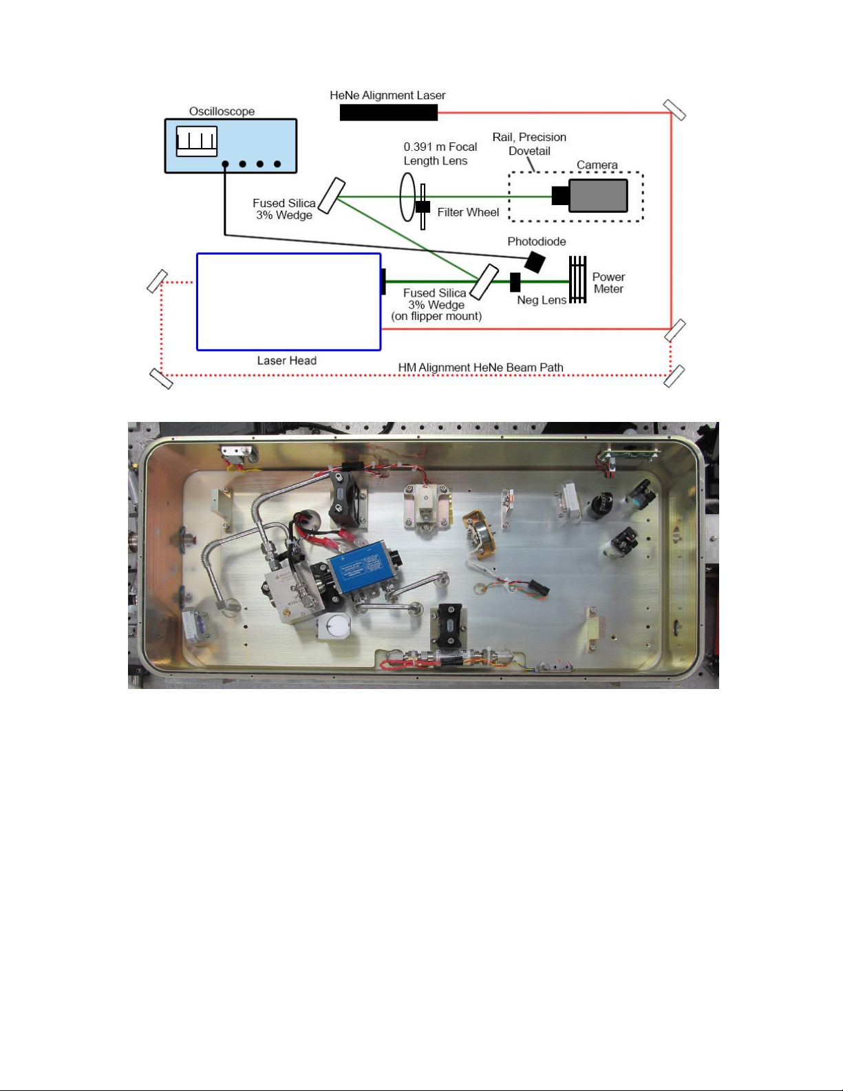
Alignment Reference, Test Set-up and Laser Layout
If possible, the laser should be referenced to a HeNe (or similar alignment laser)
prior to any modifications to the laser. The ideal testing and tuning set-up is
shown in Figure 1-1. The layout and location of the laser components are shown
in Figure 1-2.
Chapter 1: General Instructions
© 2019 Cutting Edge Optronics 5 Patara II and Iklwa II Service Manual
Figure 1-1: Laser Alignment and Test Set-up Diagram
c
Figure 1-2: Optical Bench Overview

Chapter 1: General Instructions
© 2019 Cutting Edge Optronics 6 Patara II and Iklwa II Service Manual
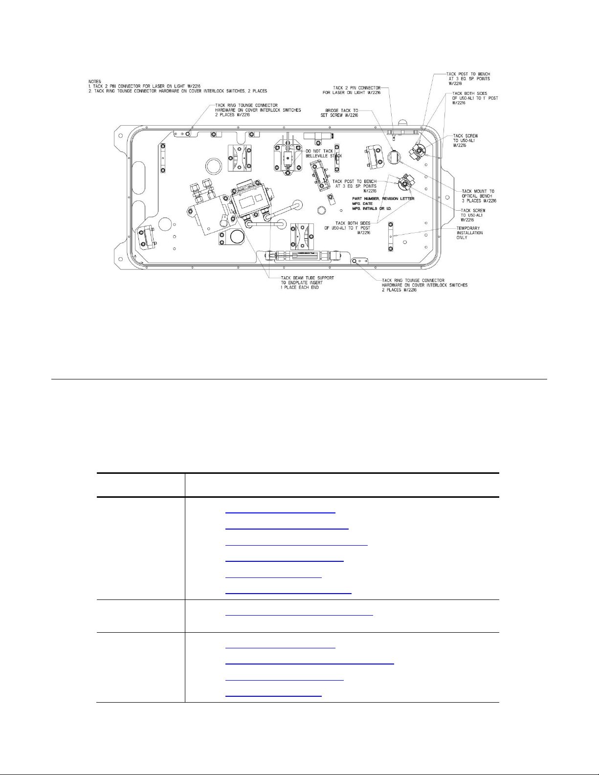
Figure 1-3: Laser Layout and Component Locations
Fastener Torque and Tack Locations
After replacement of laser components, all fasteners should be tightened, unless
otherwise specified, to the recommended torque value contained in Table 1-1,
below
Table 1-1: Recommended Torque Values
Fastener
Size
Recommended
Torque (IN-LBS)
4-40
5.5 +/- 0.5
6-32
14 +/- 1
8-32
25 +/- 1
10-32
40 +/- 2
1/4-20
80 +/- 3
Tack locations are shown in Figure 1-3. NG recommends using 3M 2216 for
tacking components and fasteners as indicated. Allow for a minimum of 12 hours
of curing time before closing the laser housing.
Chapter 1: General Instructions
© 2019 Cutting Edge Optronics 7 Patara II and Iklwa II Service Manual
Figure 1-4: Laser Tack Locations
Servicing the Laser
The following table lists the recommended order of procedures to successfully
perform service operations on the laser. Refer to the sections contained in this
service manual for detailed instructions.
Table 1-2: Service Action Table
Service
Operation
Order of procedures
Replacing the
Aperture
1. Remove Cover (page 28)
2. Aperture Removal (page 13)
3. Aperture Replacement (page 14)
4. Tack Components (page 6)
5. Install Cover (page19)
6. Laser Optimization (page 43)
Replace
Desiccant
1. Desiccant Replacement (page 14)
Replacing the
Emission Light
1. Remove Cover (page 28)
2. Emission Light Replacement (page 16)
3. Tack Components (page 6)
4. Install Cover (page19)

Chapter 1: General Instructions
© 2019 Cutting Edge Optronics 8 Patara II and Iklwa II Service Manual
Service
Operation
Order of procedures
Replacing the
Flow Switch
1. Remove Cover (page 28)
2. Coolant Line Purge (page 14)
3. Flow Switch Assembly Replacement (page 16)
4. Leak Test (page 45)
5. Install Cover (page19)
Replace the Fold
Mirror or OC
Optic
1. Remove Cover (page 28)
2. Fold Mirror / Output Coupler Replacement (page 17)
3. Defeat Cover Interlocks (page 41)
4. Power Laser for Alignment (page 39)
5. Check for Bullseye (page 40)
If concentric go to step 7
6. HR/HM Alignment (page 17-18) (HR first if replacing Fold
Mirror, HM first if replacing OC)
7. Check Hold-Off (page 40)
8. Install Cover (page19)
9. Laser Optimization (page 43)
10. Check Hold-Off (page 40)
Replace the HM
1. Remove Cover (page 28)
2. Align HeNe to Optic (page 12) (reference point)
3. HM Replacement (page 17)
Use HM adjustment screws to align HeNe reflection
back to reference point.
4. Defeat Cover Interlocks (page 41)
5. Power Laser for Alignment (page 39)
6. Check for Bulleye (page 40)
If concentric go to Step 8
7. HR/HM Alignment (page 17-18) (HR alignment may not be
necessary)
8. Check Hold-Off (page 40)
9. Tack Components (page 6)
10. Install Cover (page19)
11. Laser Optimization (page 43)
12. Check Hold-Off (page 40)

Chapter 1: General Instructions
© 2019 Cutting Edge Optronics 9 Patara II and Iklwa II Service Manual
Service
Operation
Order of procedures
Replace the HR
1. Remove Cover (page 28)
2. Align HeNe to Optic (page 12) (reference point)
3. HR Replacement (page 18)
4. Defeat Cover Interlocks (page 41)
5. Power Laser for Alignment (page 39)
6. Check for Bullseye (page 40)
If concentric go to step 8
7. HR/HM Alignment (page 17-18) (HM alignment may not be
necessary)
8. Check Hold-Off (page 40)
9. Tack Components (page 6)
10. Install Cover (page19)
11. Laser Optimization (page 43)
12. Check Hold-Off (page 40)
Replacing the
Interlocks
1. Remove Cover (page 28)
2. Interlock Replacement
3. Install Cover (page19)

Chapter 1: General Instructions
© 2019 Cutting Edge Optronics 10 Patara II and Iklwa II Service Manual
Service
Operation
Order of procedures
Replacing the
Module
1. Coolant Line Purge (page 14)
2. Remove Cover (page 28)
3. Polarizer Removal and Installation (page 26)
Step 1-2
4. HR Replacement (page 18)
Step 1
5. Laser Module Replacement (page 23)
6. Aperture Remove (page 13)
7. HM Replacement (page 17)
Removal Only
1. Remove Q-switch from Beam Path (page 29)
2. SHG Crystal Replacement and Alignment (page 30)
Step 1-2
3. Laser Module Alignment (page 20)
4. Q-Switch Replacement (page 27)
Replacement Steps Only
5. Polarizer Removal and Installation (page 26)
Installation Only
6. Leak Test (page 45)
7. Defeating the Cover Interlocks (page 41)
8. Power the Laser for Alignment (page 39)
9. SHG Replacement and Alignment (Step 15-20)
10. HR/HM Alignment (page 17-18)
11. Align Q-switch for Hold-Off (page 39)
12. Aperture Replacement (page 14)
13. Tack Components (page 6)
14. Install Cover (page19)
15. Laser Optimization (page 43)
16. Check Hold-Off (page 40)
Replacing the
Output Window
1. Output Window Replacement (page 26)
Replacing the
Polarizer
Assembly
1. Remove Cover (page 28)
2. Polarizer Assembly Removal and Replacement (page 26)
3. Tack Components (page 6)
4. Install Cover (page19)
5. Power Laser on for Alignment (page 39)
6. Laser Optimization (page 43)
7. Check Hold-Off (page 40)
This manual suits for next models
1
Table of contents
Other NORTHROP GRUMMAN Measuring Instrument manuals

NORTHROP GRUMMAN
NORTHROP GRUMMAN IKA-012-QTG User manual

NORTHROP GRUMMAN
NORTHROP GRUMMAN Patara EPL-016-QTG User manual

NORTHROP GRUMMAN
NORTHROP GRUMMAN Patara II Manual

NORTHROP GRUMMAN
NORTHROP GRUMMAN Patara I User manual

NORTHROP GRUMMAN
NORTHROP GRUMMAN IR Patara Laser System User manual

NORTHROP GRUMMAN
NORTHROP GRUMMAN NORMARC 7710 NAV User manual

NORTHROP GRUMMAN
NORTHROP GRUMMAN Sperry Marine NAVIGAT X MK 2 User manual


