Berthold Uni-Probe LB 491 User manual
JO
7LPH
User’s Manual
ID-No. 38478BA2B
Rev.-No.: 01 27.5.08
Embedded Soft. Rev. 100
Device Description Rev. 03/04 HART
Device Description Rev. 01 PA
Device Description Rev. 01 FF
Process Control detect and identify
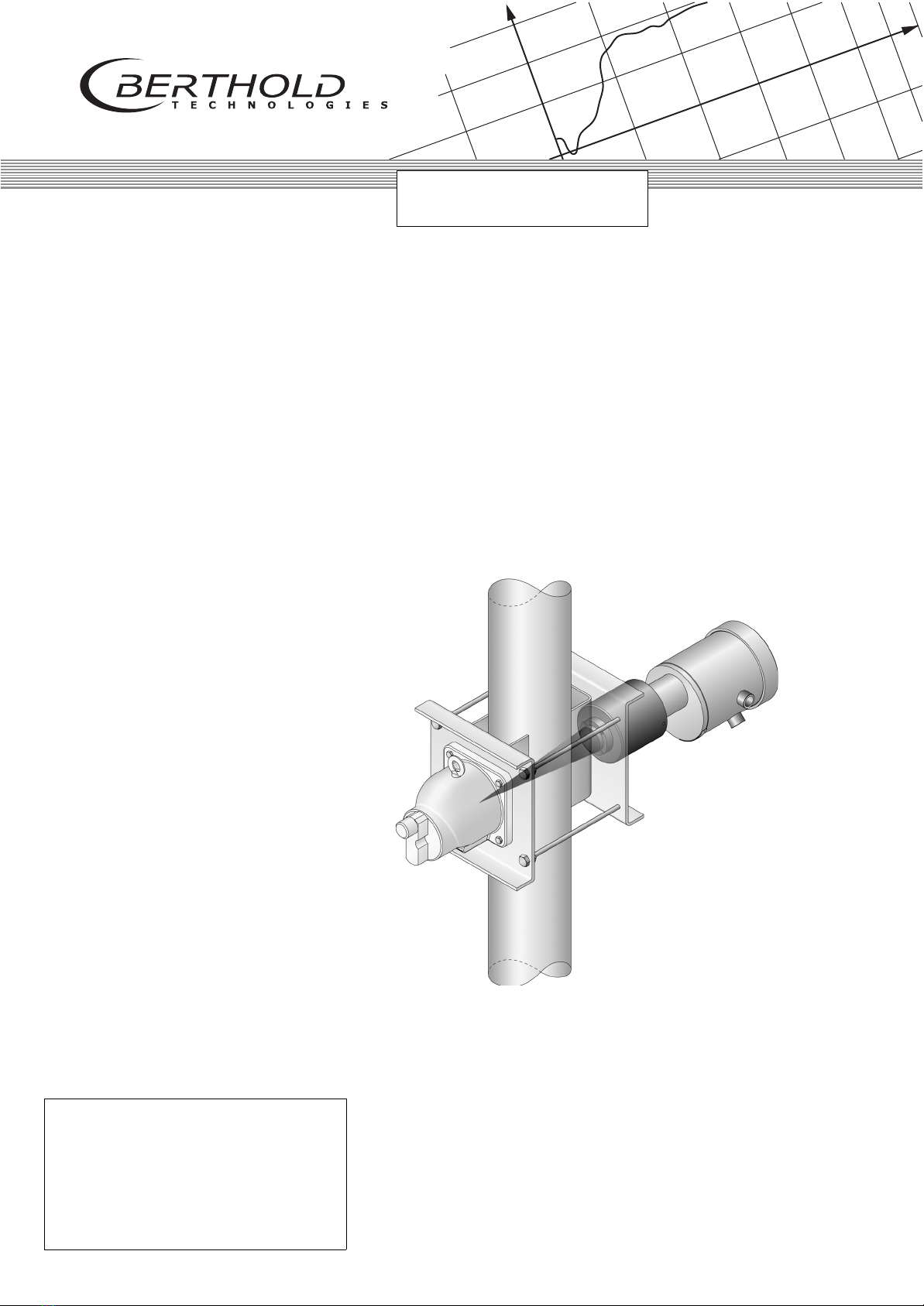
Density Measurement
Uni-Probe LB 491
With All Supplements


38478BA2B
1 – 4 27.5.08
Volume 1-7
General Information
Dear customers Thank you very much for purchasing the density measuring system
Uni-Probe LB 491 made by Berthold Technologies GmbH & Co. KG.
The scope of supply also includes this User’s Manual. Be sure to
have this User’s Manual always to hand.
Please read the User’s Manual prior to installation to get acquainted
with the product.
To avoid physical injury and property damage, please observe the
warnings and safety instructions provided in this User’s Manual.
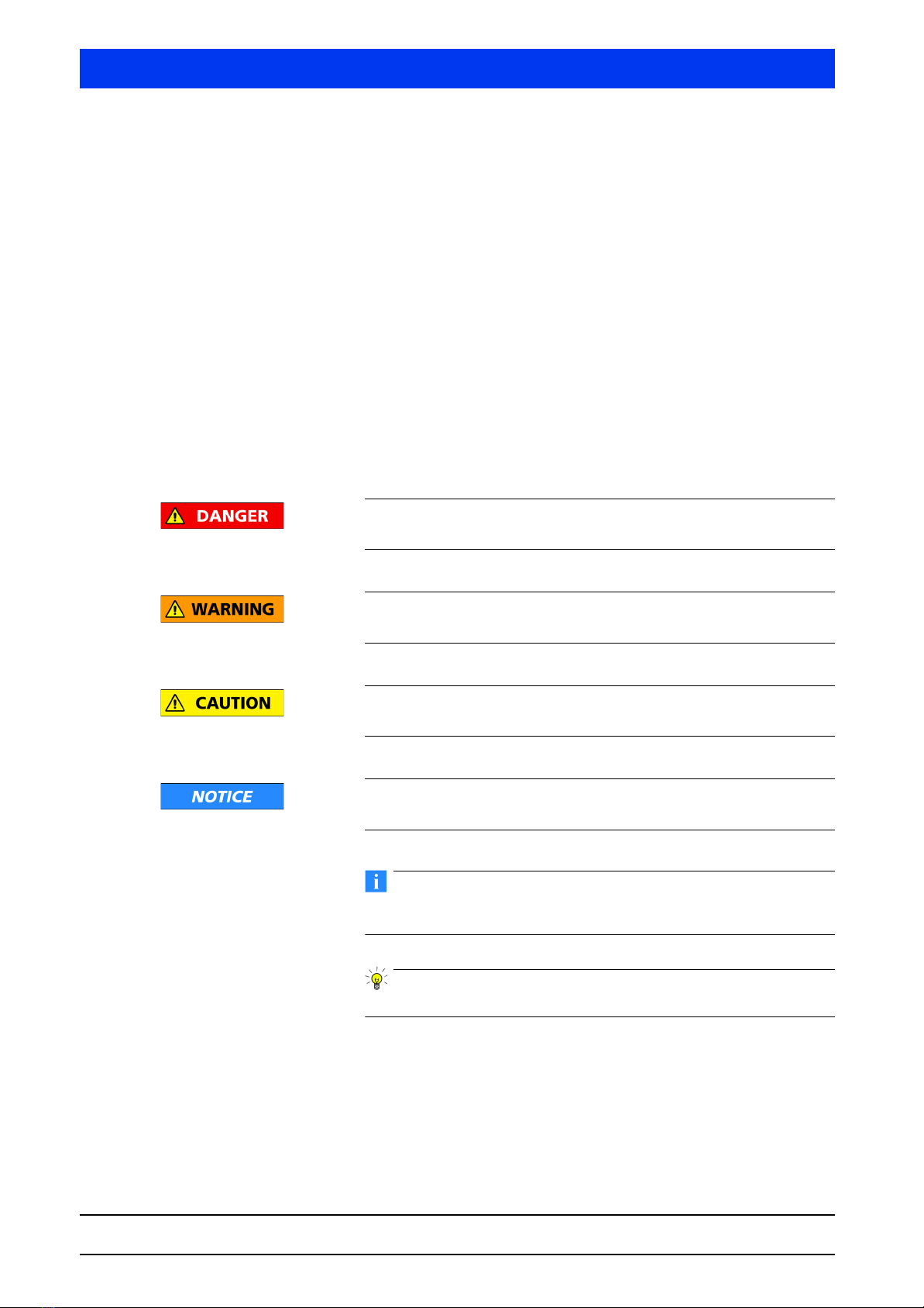
They are identified as follows: DANGER, WARNING, CAUTION or
NOTICE. In Volume 2, "Safety Manuals", you find a summary of all
safety hazards and information how to deal with them.
Indicates an imminently dangerous condition. Failure to fol-
low the instructions will lead to death or serious injury.
Indicates a potentially dangerous condition. Failure to follow the
instructions may lead to death or serious injury.
Indicates a potentially dangerous condition. Failure to follow the
instructions may lead to a slight injury or a medium-degree injury.
Indicates a situation which may cause property damage if the
instructions are not followed.
IMPORTANT
Paragraphs with this symbol provide important information on the
product or how to work with the product.
Tip
Includes application tips and other useful information.

Uni-Probe LB 491
Berthold Technologies GmbH & Co. KG 1 – 5
Volume 1-7
Typographical Conventions
The symbols and typefaces used in this User’s Manual have the
following meaning:
If you do encounter problems despite careful study of the User’s
Manual, please do not hesitate to contact us.
Your Uni-Probe LB 491 team
prompts you to carry out an action.
1, 2, 3, … identifies items in a graphic.
• identifies enumerations.
italic typeface highlights important information.
SMALL CAPS indicate commands or menu items.

38478BA2B
1 – 6 27.5.08
Volume 1-7

Uni-Probe LB 491
Berthold Technologies GmbH & Co. KG 7
Volume 1-7 Table of Contents
Volume 1 Uni-Probe Installation
1General Information.......................................................... 1 – 21
1.1 General Safety Precautions ....................................... 1 – 21
1.2 Use and Function...................................................... 1 – 21
1.3 Specific Warnings .....................................................1 – 22
1.4 Radiation Protection Guidelines ................................ 1 – 23
2System Description............................................................ 1 – 25
2.1 Measuring System .................................................... 1 – 25
2.2 Uni-Probe Hardware ................................................. 1 – 27
2.3 Measuring Principle .................................................. 1 – 30
2.4 Basic Measuring Configuration ................................. 1 – 31
2.5 Technical Data .......................................................... 1 – 32
2.6 Detector Code ..........................................................1 – 35
2.7 Uni-Probe LB 491 Nomenclature ............................... 1 – 35
2.8 LB Numerical Code ................................................... 1 – 36
3Installation ........................................................................1 – 37
3.1 Transport to the Installation Site................................1 – 39
3.2 Radioactive Sources .................................................. 1 – 41
3.3 Installation on Pipelines ............................................ 1 – 46
3.4 Installation in a Container .........................................1 – 49
3.5 Detector Protection................................................... 1 – 51
3.6 Installation of Pt100 ................................................. 1 – 53
4Electrical Installation.......................................................... 1 – 55
4.1 Conduits ..................................................................1 – 56
4.2 Terminals .................................................................. 1 – 59
4.3 Switch Setting .......................................................... 1 – 61
4.4 Connecting the Uni-Probe .......................................1 – 63
4.5 Uni-Probe with Ex i Current Output .......................... 1 – 65
4.6 Uni-Probe with Signal Output Profibus PA /
FOUNDATION™Fieldbus (not intrinsically safe)..........1 – 76
4.7 Uni-Probe with Intrinsically Safe Signal Output
Profibus PA / FOUNDATION™Fieldbus.......................1 – 79
5Repair, Maintenance and Service ....................................... 1 – 83
5.1 General Safety Precautions ....................................... 1 – 83
5.2 Visual Inspection of the Uni-Probe ............................ 1 – 85
5.3 Checking the Connection Box ..................................1 – 86

38478BA2B
827.5.08
Table of Contents Volume 1-7
5.4 Trouble Shooting ...................................................... 1 – 87
5.5 Replacing the Complete Uni-Probe .......................... 1 – 89
5.6 Replacing the Electronics Module ............................. 1 – 90
5.7 Replacing the Crystal-Multiplier Assembly................. 1 – 93
5.8 Replacing the Digital Board....................................... 1 – 94
5.9 Replacing the Power Supply Unit .............................. 1 – 96
5.10 Replacing Fuses ........................................................ 1 – 97
5.11 Updating the Embedded Software in the Uni-Probe.. 1 – 98
5.12 Scintillation Detector .............................................. 1 – 103
5.13 Customer Service.................................................... 1 – 106
5.14 Returning Repairs ................................................... 1 – 107
6Certificates ..................................................................... 1 – 109
6.1 ATEX Certificate ..................................................... 1 – 109
6.2 FM Certificate......................................................... 1 – 121
6.3 CSA Certificate....................................................... 1 – 122
6.4 EG Declaration of Conformity................................. 1 – 124
7Screw Fittings and Accessories ........................................ 1 – 125
7.1 ATEX Cable Screw Fittings ...................................... 1 – 125
7.2 ATEX-Adapter (Ex d IIC) for Screwed Cable Glands . 1 – 127
7.3 Dummy Plug........................................................... 1 – 127
7.4 Material Safety Data Sheet for Lubricant OKS 217 .. 1 – 128
8Technical Drawings ......................................................... 1 – 131
8.1 Point Detector with Frontal Irradiation .................... 1 – 131
8.2 Point Detector with Lateral Irradiation..................... 1 – 132
8.3 Point Detector Mounting Clamps............................ 1 – 133
8.4 Sunscreen............................................................... 1 – 133
8.5 Point Detector Installation on a Container............... 1 – 134
8.6 Holder Mounted on Uni-Probe................................ 1 – 134
8.7 Instructions for Installation of the Water Cooling .... 1 – 135
8.8 Required Amount of Cooling Water for Point
Detector ................................................................. 1 – 135
8.9 Point Source Shielding LB 744X .............................. 1 – 136

Uni-Probe LB 491
Berthold Technologies GmbH & Co. KG 9
Volume 1-7 Table of Contents
Volume 2 Safety Manuals
1Safety Instructions...........................................................2 – 153
2Transport and Assembly ..................................................2 – 157
3Radiation Protection........................................................ 2 – 159
3.1 General Information and Guidelines ....................... 2 – 159
3.2 Mounting the Shielding .......................................... 2 – 161
3.3 Safety Measures .....................................................2 – 164
3.4 Protection against Theft.......................................... 2 – 164
3.5 Accidents, Loss, Damage, Fire, Theft ....................... 2 – 165
3.6 Shielding and Source .............................................. 2 – 167
3.7 Leak Test ................................................................ 2 – 169
4Source Replacement ....................................................... 2 – 171
4.1 Point Source Replacement ...................................... 2 – 171
4.2 Radiation Exposure during Source Replacement ......2 – 174
5Source Disposal............................................................... 2 – 175
6Safety Instructions for the Types of Protection
ATEX / FM / CSA .............................................................2 – 179
6.1 Overview Ex-Versions.............................................. 2 – 181
6.2 Type of Protection ATEX.......................................... 2 – 182
6.3 Type of Protection FM/CSA .....................................2 – 183

38478BA2B
10 27.5.08
Table of Contents Volume 1-7
Volume 3 HART®Communicator User Interface
1General Information on the HART®Communicator......... 3 – 189
1.1 Connection, Power On and Power Off of the
HART®Communicator ........................................... 3 – 189
1.2 Working with the HART®Communicator ............... 3 – 190
2Menu Structure............................................................... 3 – 191
2.1 Information on the Menu Structure ........................ 3 – 191
2.2 Menu Overview ...................................................... 3 – 192
2.3 Start Menu ............................................................. 3 – 194
2.4 LIVE DISPLAY .......................................................... 3 – 195
2.5 PROBE RAW DATA.................................................. 3 – 196
2.6 VIEW PARAMETERS ................................................ 3 – 196
2.7 PROCESS VARIABLES .............................................. 3 – 197
2.8 SHOW CAL. DATA .................................................. 3 – 198
2.9 STATUS / ERROR LOG ............................................. 3 – 199
2.10 SHOW ERROR LOG................................................. 3 – 200
2.11 REVIEW .................................................................. 3 – 201
2.12 ACCESS TO SETUP.................................................. 3 – 203
2.13 ENTER PASSWORD ................................................. 3 – 204
2.14 SETUP..................................................................... 3 – 205
2.15 CONFIGURATION.................................................... 3 – 205
2.16 GENERAL DATA ...................................................... 3 – 206
2.17 SYSTEM PARAMETER.............................................. 3 – 207
2.18 MEASURE PARAMETER........................................... 3 – 208
2.19 DAMPING DATA ..................................................... 3 – 209
2.20 RAD. INTERFERENCE............................................... 3 – 211
2.21 PULSE RATE LIMITS ................................................. 3 – 212
2.22 TEMP. COMPENSATION .......................................... 3 – 213
2.23 SUSPENSION MEAS. ............................................... 3 – 213
2.24 CALIBRATION I/O.................................................... 3 – 214
2.25 CALIBRATION ......................................................... 3 – 214
2.26 CAL. DATA ............................................................. 3 – 215
2.27 ENTER CAL. DATA .................................................. 3 – 216
2.28 ADJUST CURVE ...................................................... 3 – 217
2.29 SAVE & LOAD CURVE............................................. 3 – 218
2.30 INPUT / OUTPUT ..................................................... 3 – 218
2.31 CURRENT I/O .......................................................... 3 – 218
2.32 COUT1 (PV)............................................................ 3 – 219

Uni-Probe LB 491
Berthold Technologies GmbH & Co. KG 11
Volume 1-7 Table of Contents
2.33 CIN1 (TEMP) ...........................................................3 – 220
2.34 DIGITAL OUT CONFIG............................................. 3 – 221
2.35 DIGITAL INPUTS ......................................................3 – 222
2.36 SERVICE ................................................................. 3 – 222
2.37 TEST CALCULATION................................................3 – 223
2.38 I/O Test ................................................................... 3 – 224
2.39 STATUS DIG. INPUT.................................................3 – 224
2.40 DIG. OUTPUT TEST ................................................. 3 – 224
2.41 CURRENT I/O TEST..................................................3 – 225
2.42 ANALOG OUTPUT 1 ............................................... 3 – 225
2.43 ANALOG INPUT 1/2 ................................................ 3 – 226
2.44 ADJUST Pt100 ........................................................ 3 – 226
2.45 PROBE SETTINGS ....................................................3 – 226
2.46 HV SETTINGS.......................................................... 3 – 227
2.47 PLATEAU ................................................................ 3 – 228
2.48 HART®INTERFACE..................................................3 – 229
3Getting Started via the HART®Communicator ................ 3 – 231
3.1 Steps for Getting Started ........................................ 3 – 231
3.2 Setup Protocol ........................................................ 3 – 232
3.3 Calibration Values................................................... 3 – 234
4Calibration...................................................................... 3 – 235
4.1 Preparing Calibration .............................................. 3 – 235
4.2 Measure Background.............................................. 3 – 242
4.3 Operation Modes for Calibration ............................3 – 245
4.4 Two- and Multi-Point Calibration ............................3 – 248
4.5 One-Point Calibration ............................................. 3 – 253
4.6 Suspension Calibration ...........................................3 – 257
4.7 Temperature Compensation....................................3 – 262
4.8 Correcting the Measured Values ............................. 3 – 267
5Functional Processes .......................................................3 – 269
5.1 Plateau Measurement ............................................. 3 – 269
5.2 Changing the Uni-Probe Password.......................... 3 – 271
6Explanations ................................................................... 3 – 273
6.1 Background ............................................................ 3 – 273
6.2 Radiation Interference Detection............................. 3 – 275
6.3 Reading-in Pulse Rates............................................ 3 – 278
6.4 Calibration Modes ..................................................3 – 280

38478BA2B
12 27.5.08
Table of Contents Volume 1-7
6.5 Measurement of Suspensions ................................. 3 – 286
6.6 Software Versions................................................... 3 – 291
7Tables ............................................................................. 3 – 297
7.1 Absorption coefficients........................................... 3 – 297
7.2 Temperature coefficients......................................... 3 – 298
7.3 Density of Water as a Function of the Temperature . 3 – 300
8Error Handling ................................................................ 3 – 301
8.1 Device Response to Errors....................................... 3 – 301
8.2 Error Handling Modes............................................. 3 – 302
8.3 Corrective Action.................................................... 3 – 302
8.4 Reset ...................................................................... 3 – 304
8.5 Operation Modes during Measurement .................. 3 – 304
8.6 Error Reset.............................................................. 3 – 305
8.7 Fault Current .......................................................... 3 – 306
9Setup Protocol ................................................................ 3 – 309
9.1 Parameter List......................................................... 3 – 309
9.2 Calibration Values................................................... 3 – 311

Uni-Probe LB 491
Berthold Technologies GmbH & Co. KG 13
Volume 1-7 Table of Contents
Volume 4 PACTware™User Interface FDT/DTM
1PC Connection to the Uni-Probe ..................................... 4 – 317
2Installing and Working with DTM ....................................4 – 319
2.1 Requirements ......................................................... 4 – 319
2.2 FDT Container ........................................................ 4 – 319
2.3 DTM Communication Software...............................4 – 320

38478BA2B
14 27.5.08
Table of Contents Volume 1-7
Volume 5 SIMATIC PDM User Interface HART®
1PC Connection to the Uni-Probe ..................................... 5 – 329
2General Information on SIMATIC PDM ............................ 5 – 331
2.1 Hardware Requirements ......................................... 5 – 332
2.2 Fifo Buffer .............................................................. 5 – 332
3Getting Started with SIMATIC PDM................................. 5 – 335
3.1 First Steps............................................................... 5 – 335
3.2 Installing SIMATIC PDM .......................................... 5 – 335
3.3 Installing the Uni-Probe LB 491 Device Description.. 5 – 339
3.4 Project Setup .......................................................... 5 – 340
3.5 Starting SIMATIC PDM............................................ 5 – 344
4Menu Overview .............................................................. 5 – 345
4.1 FILE Menu .............................................................. 5 – 346
4.2 DEVICE Menu......................................................... 5 – 359
4.3 VIEW Menu ............................................................ 5 – 394
4.4 OPTIONS Menu ...................................................... 5 – 400
4.5 HELP Menu............................................................. 5 – 406
5Calibration with SIMATIC PDM........................................ 5 – 407
5.1 Preparing Calibration.............................................. 5 – 407
5.2 Measure Background.............................................. 5 – 412
5.3 Operation Modes for Calibration ............................ 5 – 414
5.4 Two- and Multi-Point Calibration ............................ 5 – 416
5.5 One-Point Calibration ............................................. 5 – 420
5.6 Suspension Calibration ........................................... 5 – 423
6Functional Processes ....................................................... 5 – 425
6.1 Plateau Measurement............................................. 5 – 425
6.2 Changing the Uni-Probe Password.......................... 5 – 428
7Explanations ................................................................... 5 – 431
7.1 Background............................................................ 5 – 431
7.2 Radiation Interference Detection............................. 5 – 433
7.3 Reading-in Count Rates .......................................... 5 – 436
7.4 Calibration Modes .................................................. 5 – 438
7.5 Measurement of Suspensions ................................. 5 – 444

Uni-Probe LB 491
Berthold Technologies GmbH & Co. KG 15
Volume 1-7 Table of Contents
8Error Handling ................................................................ 5 – 449
8.1 Device Response to Errors .......................................5 – 449
8.2 Error Handling Modes............................................. 5 – 450
8.3 Corrective Action....................................................5 – 451
8.4 Reset ...................................................................... 5 – 452
8.5 Operation Modes during Measurement .................. 5 – 453
8.6 Error Reset.............................................................. 5 – 453
8.7 Fault Current .......................................................... 5 – 454
9Working with SIMATIC PDM ...........................................5 – 457
9.1 Starting SIMATIC PDM ............................................ 5 – 457
9.2 The SIMATIC PDM Main Window ...........................5 – 458
9.3 Device Icons in SIMATIC PDM ................................. 5 – 461

38478BA2B
16 27.5.08
Table of Contents Volume 1-7
Volume 6 SIMATIC PDM User Interface Profibus PA
1Process Operation ........................................................... 6 – 467
1.1 Important Information on the Operation................. 6 – 467
1.2 Alternative Operation via HART®............................ 6 – 467
1.3 System Overview .................................................... 6 – 468
2Installation / Program Start.............................................. 6 – 469
2.1 Installing the Device Description (DD)...................... 6 – 469
2.2 Starting SIMATIC PDM............................................ 6 – 470
3Device-specific Menus..................................................... 6 – 471
3.1 DEVICE Menu......................................................... 6 – 472
3.2 VIEW Menu ............................................................ 6 – 510
4Calibration with SIMATIC PDM........................................ 6 – 519
4.1 Preparing Calibration.............................................. 6 – 519
4.2 Operation Modes for Calibration ............................ 6 – 527
4.3 Two- and Multi-Point Calibration ............................ 6 – 529
4.4 One-Point Calibration ............................................. 6 – 534
4.5 Suspension Calibration ........................................... 6 – 538
5Functional Processes ....................................................... 6 – 541
5.1 Plateau Measurement............................................. 6 – 541
5.2 Define Unit of Measure and Unit for the Function
Blocks..................................................................... 6 – 546
6Explanations ................................................................... 6 – 549
6.1 Background............................................................ 6 – 549
6.2 Radiation Interference Detection............................. 6 – 551
6.3 Reading-in Pulse Rates............................................ 6 – 554
7Error Handling ................................................................ 6 – 557
7.1 Device Response in Case of Errors........................... 6 – 557
7.2 Error Handling Modes............................................. 6 – 558
7.3 Corrective Action.................................................... 6 – 558
7.4 Reset ...................................................................... 6 – 560
7.5 Operation Modes during Measurement .................. 6 – 560

Uni-Probe LB 491
Berthold Technologies GmbH & Co. KG 17
Volume 1-7 Table of Contents
Volume 7 FOUNDATION™Fieldbus User Interface
1Process Operation ........................................................... 7 – 565
1.1 Important Information on the Operation.................7 – 565
2Installation / Program Start .............................................. 7 – 567
2.1 Installing the Device Description..............................7 – 567
2.2 Addressing the Density Meter Uni-Probe LB 491 .....7 – 567
3Parameter Overview........................................................ 7 – 569
3.1 Parameters for the Function Block Resource............7 – 569
3.2 Parameters for the Function Block Transducer .........7 – 570
3.3 Parameters for the Function Blocks Analog Input ....7 – 577
3.4 Parameters for the Function Blocks Analog Output .7 – 577
4Calibration with FOUNDATION™Fieldbus........................ 7 – 579
4.1 Preparing Calibration .............................................. 7 – 579
4.2 Set Background ......................................................7 – 581
4.3 Operation Modes for Calibration ............................7 – 582
4.4 Two- and Multi-Point Calibration ............................7 – 584
4.5 One-Point Calibration ............................................. 7 – 587
4.6 Suspension Calibration ...........................................7 – 589
5Functional Processes .......................................................7 – 591
5.1 Plateau Measurement ............................................. 7 – 591
5.2 Test Calculation (Test Signal Output) .......................7 – 593
5.3 Damping ................................................................7 – 594
5.4 Radiation Interference Detection............................. 7 – 596
5.5 Input Configuration................................................ 7 – 596
5.6 Relay Configuration................................................ 7 – 597
5.7 Defining the Upper/Lower Pulse Rate Limit.............. 7 – 598
5.8 Protecting Parameters against Modification ............7 – 599
5.9 Reading Out the Error Log ...................................... 7 – 599
6Explanations ................................................................... 7 – 601
6.1 Background ............................................................ 7 – 601
6.2 Radiation Interference Detection............................. 7 – 603
6.3 Reading-in Pulse Rates............................................ 7 – 606
7Error Handling ................................................................ 7 – 607
7.1 Device Response in Case of Error ............................7 – 607
7.2 Error Handling Modes............................................. 7 – 608


JO
7LPH
Volume 1 Uni-Probe Installation

38478BA2B
1 – 20 27.5.08
Volume 1
Table of contents
Other Berthold Measuring Instrument manuals

Berthold
Berthold MicroPolar LB 566 User manual

Berthold
Berthold DuoXpert LB 476 Level+ User manual

Berthold
Berthold Duo XPERT LB 470 Level User manual

Berthold
Berthold LB 442 User manual

Berthold
Berthold LB 444 K-40 User manual

Berthold
Berthold Duo Series User manual

Berthold
Berthold LB 9510 User manual

Berthold
Berthold Duo Xpert LB 478 MPLM User manual

Berthold
Berthold LB 444 User manual

Berthold
Berthold BTwave LB 571-02 User manual


