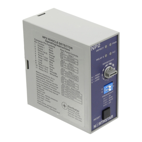
NorthStar NT11 User manual

Manual Contents
Glossary Page1
Description Page2
Characteristics Page2
Installation Page3
Adjustments Page4
Connections Page 6
Theory of Operation Page 6
Block Diagram Page 7
Detailed Description of Operation Page 7
PartsList Page9
Schematic Page10
Glossary
d.c. Direct Current
DIL Dual In-Line
led Light Emitting Diode
Megger Meg Ohmmeter
msec millisecond
pk-pk Peak to Peak
uH Micro henry
uF Micro farad
Page 1

Description – NT11 and NT11-E
Northstar Controls LLC single channel NT11 and single channel with extend & delay timing
NT11-E quality products of the latest design to provide consistent response times, and superior
noise immunity for reliable operation.
The NT11 and NT11-E have four operating frequencies controlled by front panel DIP switches
to help eliminate crosstalk between loops connected to different detectors. Tuning is fast and
automatic with correct power applied or pressing the reset. With power applied the detector will
tune to the loop and continuously track and adjust to environmental drifts. Presence time is
consistent and substantially independent of vehicle type.
Front panel indicators (LED’s) include Detect (DET) which is Red solid during current detect
and flashing to indicate extension or delay operation. Additionally the DET indicator will flash
with a particular sequence when the detector is in the fault condition. The Fault (FLT) will be
solid yellow to indicate a current fault and will flash a sequence to indicate a previous fault
condition. The fault type sequence is one flash and one space is for an open, two flashes and one
space is for a short and three flashes and a space indicate a greater than 25% inductance change.
The NT11 and NT11-E are fail-safe detectors so in fault they will provide a constant output until
the fault is cleared.
Characteristics – NT11 and NT11-E
• Operating mode: Presence = 15 minutes (Short), 120 minutes (Long), Pulse = 125ms +/-
25ms.
• Pulse paralysis: When used in pulse mode, a pulse paralysis time of two seconds is
incorporated to prevent multiple pulses being produced when a vehicle remains over the
loop for an extended period.
• Sensitivity: 16 levels of sensitivity are available, selected by front panel DIP switches.
Medium sensitivity is used for most applications, this is a setting of seven or eight.
Always use the lowest sensitivity setting that detects the desired vehicles.
• Frequency: Four separate frequency setting are controlled by front panel DIP switches.
Frequency range is 15 to 150 KHz. Always reset the detector after changing settings.
• Timing options (E model only): Output signal may be extended from 0 to 15.75 seconds
in .25 second increments and delayed from 0 to 63 seconds in 1 second increments. Both
functions are activated by front panel DIP switches. *Delay timing function may be
inhibited by a 120VAC signal (reference Neutral) applied to Pin J of the connector.
• Reset: Channel may be reset by pressing the reset button or by temporarily selecting
another sensitivity or mode setting then returning to the desired value.
Page 2

• Outputs: Relay or Optically isolated Solid State. Solid State output rating maximum
voltage 47V, ON voltage <1.5V at 50ma. Relay output rating 10A, 277VAC, 24VDC.
Output is fail-safe (assumes detect condition on power failure).
• Power: 115VAC +/- 20%,1W.
• Tuning: Automatically tunes to proper loop and lead-in with application of power.
• Inductance range: 20µH to 2000µH with a Q factor greater than 5.
• Temperature range: -40 C to +80 C.
• Lead-in length: Up to 5000 ft. with proper lead-in and loop.
• Lightning and transient protection: Loop inputs will withstand discharge of 2000V from
a 10µF capacitor across the loop connections or from either loop input to ground.
Protection exceeds NEMA specification.
• Mechanical: Dimensions are 5.5” D x 5.5” H x 2” W excluding connector.
• Weight: 1 lb.
• Indicators: Front panel indicators include, Detect – Red, solid during detect and flashing
to indicate extend or delay operation. Fault – Yellow, solid for current or flashing for
historical fault. Fault sequence is related to type of fault sensed.
1 blink and 1 space = Open
2 blinks and 1 space = Short
3 blinks and 1 space = 25% inductance change
Installation
Please use safe operating practices at all times to avoid electrical shock hazards that may
be present in the cabinet.
• Select presence or pulse, if presence then select long or short.
• Set frequency and sensitivity switches to the desired positions for the application.
Set sensitivity to the medium range (7 or 8) and work from there.
• If crosstalk is experienced with an adjacent detector, change the frequency to
allow for the maximum frequency separation between the detector units.
Page 3

• With power applied and switch settings in the desired positions, press the reset
button.
• Observe the detection of vehicles by watching the front panel detect LED.
Loop installation:
The Northstar NT11 and NT11-E detectors will operate with loop and lead-in’s whose
total inductance is between 20µH and 2000µH. Loops with a perimeter less than 30 feet
should have at least three turns, between 30 feet and 120 feet should have two turns and
over 120 feet should have one turn of wire.
Loop and lead-in should be proper loop wire, #12 or #14 AWG, lead-in should be twisted
at least seven twists per foot. Shielded lead-in’s are not essential but are recommended
especially on longer runs. Loop and lead-in should have an insulation resistance to
ground greater than 50MΩmeasured at 500V and a series resistance of less than 10Ω.
Loop size and location are a function of application and are dictated by experience.
Northstar detectors will handle a wide range of loop and lead-in systems.
Adjustments – NT11 and NT11-E
Sensitivity: Four front panel DIP switches provide for 16 sensitivity settings.
Setting Level dL/L Setting Level dL/L Setting Level dL/L
15 .01% 10 .06% 5 .32%
14 .015% 9 .08% 4 .48%
13 .02% 8 .12% 3 .64%
12 .03% 7 .16% 2 .96%
11 .04% 6 .24% 1 1.28%
0 2.56%
* see chart on page 6 for DIP positions
Frequency: Two front panel DIP switches provide for 4 frequency settings.
• F2+F1 = High
• F2+F0 = Medium High
• F1+F0 = Medium Low
• F0+F0 = Low
Page 4

Adjustments Continued – NT11 and NT11-E
F0F0 = Low
F1F0 = Med Low
F2F0 = Med High
F1F2 = High
Setting 0 = 2.56%
Setting 1 = 1.28%
Setting 2 = .96%
Setting 3 = .64%
Setting 4 = .48%
Setting 5 = .32%
Setting 6 = .24%
Setting 7 = .16%
Setting 8 = .12%
Setting 9 = .08%
Setting 10 = .06%
Setting 11 = .04%
Setting 12 = .03%
Setting 13 = .02%
Setting 14 = .015%
Setting 15 = .01%
01 23 45
6 7 8 9 10 11
12 13 14 15
Sensitivity DIP switch positions (shaded area).
Page 5

Connections – 10 pin MS 3102-A-18-P mating with MS3106-A-18-1S.
Pin # Function Color
C Power (+) Black
A Power (-) White
H Chassis Ground Green
B Relay Common Yellow
F Relay N.O. Blue
G Relay N.C. Red
D Loop Gray
E Loop Brown
I Spare White/Black
J 120VAC Timer Override White/Red
* Note: The above connection is shown with correct power supplied and no vehicle present.
Theory of Operation
Systems Description
The Northstar Controls NT11 and NT11-E sensor unit consists of the following major circuit
elements: The loop oscillator, the digital period measurement circuit, the microcontroller, the
front panel switches and indicators and the output circuits
The loop oscillator, when connected to a suitable road loop / lead-in combination, establishes an
oscillating signal the frequency of which is directly related to the inductance of the loop and
lead-in. When a vehicle enters the detection zone surrounding the loop, the inductance of the
loop changes causing the frequency of the oscillating signal to change and providing a means to
determine the presence of the vehicle. Transient protection elements are incorporated within the
oscillator to prevent large transients from causing damage to the oscillator or other electronics.
Frequency switches accessible from the front panel allow the operating frequency of the
oscillator to be modified to prevent mutual interference between oscillators associated with
different sensor boards connected to adjacent loops.
When a channel is energized, a sample of the frequency is taken and compared to a stored
reference. Sensitivity switches accessible from the front panel allow the adjustment of sensitivity
which determines the amount of change in frequency that is required between the current sample
and the reference to result in a detect call being made.
The detection call output for each sensor is made by means of a relay which is set to conduct to
indicate a vehicle detection. Front panel led indicators also indicate a vehicle detection and also
when the inductance of the road loop exceeds the operating range.
Page 6

Block Diagram of NT11/NT11-E Loop Sensor Unit
Loop
Oscillator
Frequency
Measuring
Circuit
Switches
Indicators
Indicators
Switches
Output
Microcontroller
Loop
Detailed Description of Operation
When power is applied to the sensor unit, the microcontroller first checks the condition of the
front panel switches to determine that the channel is enabled, what sensitivity level is set and
what operational mode is required. Then the loop oscillator is activated to obtain a sample of the
loop frequency.
When the loop oscillator is activated the combination of the inductance of the road loop and the
added capacitance within the oscillator circuitry produces a resonant frequency. The oscillating
signal in the road loop sets up an alternating magnetic field surrounding the loop itself. When the
conductive metal in a vehicle enters the magnetic field it acts in a similar manner to a shorted
turn and the effective inductance of the loop is reduced thus increasing the resonant frequency.
Page 7

Frequency modification switches at the front panel allow the oscillator frequency to be modified
when multiple loops and multiple sensor units are operated close to each other. This prevents
interference or crosstalk from occurring between loops connected to different sensor units. A
loop transformer within the oscillator circuitry isolates the road loop from the internal circuitry
of the sensor improving its resistance to external surges induced in the road loop and also
allowing the sensor to operate with loops that are shorted to ground.
The sinusoidal oscillations are fed through a squaring circuit to produce a square wave which is
suitable for the digital frequency measurement circuitry. The loop oscillator frequency is
measured by counting the number of oscillations from a stable crystal oscillator source which
occur over a predetermined number of loop oscillator cycles. This is known as period
measurement and defines the frequency of the loop oscillator to a very fine resolution. A
combination of the loop frequency and the selected sensitivity is used to determine the number of
cycles over which to perform the period measurement.
Once a stable oscillator condition has been established the sample is stored as a reference against
which subsequent samples will be compared. Small, slow changes in the oscillator frequency due
to environmental drift are programmed out allowing the direct comparison of fast changes due to
the entry of a vehicle in the detection zone. Once a period shift exceeding the detection threshold
set by the sensitivity level occurs, the output and detect indicator for that channel are activated.
The Operational mode that was set on the front panel switches will determine whether a single
125 millisecond output pulse is issued (pulse mode) or whether the output signal remains until
the oscillator frequency returns below the detection threshold indicating the exit of the vehicle
from the detection zone (Presence mode).
If the loop oscillator frequency exceeds the operating range of the sensor unit, as might happen
when the road loop connection is open or short circuited then a fault condition is signaled by the
detect output entering the fail-safe condition, the fault led lighting solid yellow and the detect led
indicators flashing. If the oscillator frequency should then return to within the operating range,
the detect output and led indicator will return to their normal operating state while the yellow
Event indicator will continue to flash indicating that a historical fault has occurred. The flash
sequence indicates the type of fault that was sensed. A single flash followed by a pause indicates
an open circuit loop or. A double flash followed by a pause indicates a shorted loop or too small
a loop inductance. A triple flash followed by a pause indicates a greater than 25% change in
loop inductance.
Page 8

This manual suits for next models
1
Table of contents
Other NorthStar Security Sensor manuals