manuals.online logo
Brands
  1. Home
  2. •
  3. Brands
  4. •
  5. Siemens
  6. •
  7. Security Sensor
  8. •
  9. Siemens QRI Series User manual

Siemens QRI Series User manual

CC1N7719en
02.06.2008
Building Technologies
HVAC Products
7719
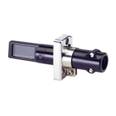
Infrared Flame Detectors QRI...
Infrared flame detectors for use with Siemens burner controls, for the supervi-
sion of gas, oil and other flames that emit infrared light.
The QRI... are suited for burners of any capacity, either in continuous or intermit-
tent operation.
The QRI... and this Data Sheet are intended for use by OEMs which integrate the
flame detectors in their products.
Use, features
Key features of the QRI... flame detectors:
- Detector with infrared-sensitive flame detecting element
- Integrated flame signal amplifier
- Designed for frontal and lateral (90°) illumination
- Suited for use with burner controls type LMV5...
- Secured to the burner with flange and clamp
The spectral sensitivity of the QRI... is a maximum of about 2 µm covering infrared
radiation emitted by gas, oil, and coal flames as well as other sources of infrared light.
Owing to electronic self-supervision of the flame signal, the QRI... can be used in con-
nection with suitable burner controls designed for burners in continuous or intermittent
operation.
The sensitivity of the QRI... is such that it must be fitted behind the burner’s baffle plate.
2/11
Building Technologies CC1N7719en
HVAC Products 02.06.2008
Warning notes
To avoid injury to persons, damage to property or the environment, the following
warning notes must be observed!
Do not open, interfere with or modify the flame detector!
•All activities (mounting, installation and service work etc.) must be performed by
qualified staff
•Before making any wiring changes in the connection area, completely isolate the
plant from mains supply (all-polar disconnection). Ensure that the plant cannot be
inadvertently switched on again and that it is indeed dead. If not observed, there is
a risk of electric shock hazard
•Ensure protection against electric shock hazard by providing adequate protection
for the burner control’s connection terminals
•Each time work has been carried out (mounting, installation, service work, etc.),
check to ensure that wiring is in an orderly state and that the correct terminals of
the LMV5... are used and make the safety checks as described in «Commissioning
notes»
•Make certain that none of the 3 connecting wires of the QRI... is connected to ter-
minal X10-02/3 (mains voltage L)! Risk of damage to QRI... and LMV5...!
•Use an AC voltmeter (Ri = 10 MΩ) to ensure that there is no voltage across the
reference line (blue wire = Nof the LMV5...) and the burner housing (PE)
•Due to its mounting location behind the baffle plate, the flame detector has high
signal sensitivity and, therefore, identifies small variations in infrared radiation as a
flame. For this reason, make certain that so-called heat streaks after loss of flame
(emitted for example by after-glowing combustion chamber lining) will not reach the
detector as these would simulate a flame. Air turbulence or similar may modulate
infrared radiation emitted by hot boiler or burner components in a way that a flame
will be simulated. Likewise, moving parts in the detector’s viewing range can cause
infrared radiation from the boiler (or a viewing tube) to be modulated, thereby pos-
sibly generating sporadic detector signals. Strong burner or detector vibrations can
also produce variations in radiation. For this reason, the burner or boiler manufac-
turer must make certain that such modulated radiation cannot reach the flame de-
tector. For example, loose cables (moving up and down in the fan’s airstream) are
not permitted within the detector’s viewing range
•Consider carefully the use of infrared flame supervision if several burners use the
same combustion chamber. In general, this type of flame supervision is not suited
for the specific supervision of individual burners
•Check to ensure that the burner will initiate lockout when – while the burner is run-
ning – the flame detector is removed from its fixing on the burner and – without
moving it – is exposed to room lighting
•Fall or shock can adversely affect the safety functions. Such units must not be put
into operation even if they do not exhibit any damage
Mounting notes
•Ensure that the relevant national safety regulations are complied with
•Secure the flame detector to the burner with the clamp and flange provided. With
the clamp’s fixing screw loosened, the detector can be correctly adjusted toward
the flame. This adjustment can be checked by watching the intensity of the flame
signal on the AZL5... display and operating unit of the LMV5... burner control, or
with the help of the measuring circuit (refer to «Detector signal measurement»)
•Ensure that the connection between the metal surface of the flange and the
burner’s earthed housing is electrically conductive
3/11
Building Technologies CC1N7719en
HVAC Products 02.06.2008
Installation notes
•Locate the detector such that, if possible, only the flickering peripheral range of the
flame will be detected. The view at hot boiler walls or other hot boiler or burner
components must be restricted as much as possible. This can be attained by
clearly confined viewing conditions behind narrow baffle plates. If this is not possi-
ble, a viewing tube should be used to restrict the viewing range to a smaller area of
the flame. Length, diameter and alignment of the viewing tube must be determined
through testing, depending on the size of burner and boiler
The viewing range should be reduced to such an extent that:
a) the minimum detector output signal required is attained over the burner’s entire
output range (for details, refer to the Basic Documentation of the LMV5...
(P7550)
b) after loss of flame, the valve’s operating voltage is switched off by the burner
control as required by the standards (refer to «Commissioning notes»).
Electrical connection of the flame detectors
It is important to achieve practically disturbance- and loss-free signal transmission:
•Never run the detector cable together will other cables
- Line capacitance reduces the magnitude of the flame signal
- Use a separate cable
•Observe the permissible length of the detector cables (refer to «Technical data»)
•Always run the ignition cable separate while observing the greatest possible dis-
tance to other cables (min. 3 cm)
•Test the flame detector on all applications. When used in connection with the
LMV5..., the test is to be made with a test routine (for details, refer to the Basic
Documentation P7550)
•Make certain that the detector’s cable does not get into contact with hot burner or
boiler surfaces
Commissioning notes
•When commissioning the plant or when doing maintenance work, make the follow-
ing safety checks:
Safety check Anticipated response
a) Burner startup with flame detector darkened Lockout at the end of
«TSA»
b) Burner startup with flame detector exposed to
extraneous light (e.g. light from an incandescent
lamp interrupted at about 20 Hz)
Lockout at the end of
the prepurge time
c) Simulation of flame failure during operation. For
that purpose, darken the flame detector during
operation and maintain this state
Lockout or restart, de-
pending on the burner
control’s configuration
d) Check the safety time in operation in the event of
loss of flame; for that purpose, disconnect manu-
ally the fuel valves from power and check the time
the burner control requires from this manual dis-
connection until the valves’ power supply is turned
off
Burner control discon-
nects power supply to
the valves within the
period of time allowed
for the relevant plant
•Make a loss-of-flame test with the AZL5... of the LMV5... burner control
4/11
Building Technologies CC1N7719en
HVAC Products 02.06.2008
Standards and certificates
Conformity to EEC directives
- Electromagnetic compatibility EMC (immunity)
- Directive for gas appliances
- Low-voltage directive
2004/108EC
90/396EEC
2006/95EC
ISO 9001: 2000
Cert. 00739 ISO 14001: 2004
Cert. 38233
For use in the U.S. / Canada, the flame detectors carry the marks.
Service notes
•To clean the detector’s lens, use a soft, clean cloth (free from oil and solvents)
Disposal notes
The flame detector contains electrical and electronic components and must not be dis-
posed of together with domestic waste.
Local and currently valid legislation must be observed.
Mechanical design
The QRI... has an impact-proof housing made of black plastic. The lens is fitted in a
dust-tight position.
The QRI... can be secured to the burner within its adjusting range, using the clamp and
the flange provided.
The 3-core connecting cable is ready connected to the QRI... and features cable strain
relief.
Depending on the type of burner construction, there are flame detectors for frontal or
lateral illumination available.
Type summary
Type reference Illumination Cable length «L» Cable end Accessories
QRI2A2.B180B Frontal 180 cm Stripped ---
QRI2B2.B180B Lateral 180 cm Stripped ---
QRI2B2.B180B1 Lateral 180 cm Stripped Flange and
clamp
When ordering, please give the complete type reference according to «Type sum-
mary».
Only in connection with
the burner control
5/11
Building Technologies CC1N7719en
HVAC Products 02.06.2008
Accessories
Flange, with radius 4 241 8855 0
Flange, straight 4 241 8898 0
Clamp 4 199 8806 0
Mounting kit AGG2.110
For frontal illumination, including heat insulator with ¾“ 14-NPSM
thread
Adapter, protective sleeve Pg9 / ½“ 14-NPSM thread AGG2.120
Technical data
Operating voltage
- Operation
- Test
DC 14 V ±5 %
DC 21 V ±5 %
Signal voltage DC 0...5 V
Length of connecting cable Max. 180 cm
Degree of protection IP54
Power consumption < 0.5 W
Length of auxiliary detector cable Max. 100 m
Safety class II
Vibrations to IEC 6068-2-6 max. 1 g / 10...500 Hz
Weight incl. cable 180 cm approx. 0.175 kg
Mounting position optional
Storage DIN EN 60 721-3-1
Climatic conditions class 1K3
Mechanical conditions class 1M2
Temperature range -20...+60 °C
Humidity < 95 % r.h.
Transport DIN EN 60 721-3-2
Climatic conditions class 2K2
Mechanical conditions class 2M2
Temperature range -20...+60 °C
Humidity < 95 % r.h.
Operation DIN EN 60721-3-3
Climatic conditions class 3K5
Mechanical conditions class 3M2
Temperature range -20...+60 °C
short-time (max. 1 min) up to 75 °C
Humidity < 95 % r.h.
Condensation, formation of ice and ingress of water are not permitted!
General detector data
Environmental
conditions
6/11
Building Technologies CC1N7719en
HVAC Products 02.06.2008
Function
With this type of flame supervision, the changes in infrared radiation are used to gener-
ate the flame signal. The flame-detecting element is an infrared-sensitive photoresistor
whose spectral sensitivity covers the range of approximately 1...3 µm. The detector
does not respond to constant radiation or radiation with mains frequency harmonics
(e.g. 50 Hz or multiples thereof). The suppression of these radiation frequencies is
made electronically, directly dependent on the current mains frequency at which the
relevant burner control (e.g. LMV5...) is operated. As a result, filtering takes place
within a very narrow band, which means that the signal generated by the flame can
almost completely be utilized since the frequency and the rate of change of infrared
radiation constantly change. Hence, the detector’s ability to capture the flame’s radia-
tion behind the burner’s baffle plate is extremely high. As a result of the high level of
sensitivity, constant or mains frequency-harmonic extraneous light sources remain
undetected only if the detector itself is not moved. Due to its short-wave spectrum, the
ignition spark will not be detected. The detector’s analog output signal (0... approx. +5
V) is a measure of the changes of the flame’s radiation intensity.
If the connecting cable length of 180 cm is not sufficient, the burner manufacturer can
extend it up to a maximum of 100 m (also refer to «Installation notes»).
7719m04/1199
SIEMENS
QRI
Made in Germany
Landis & Staefa
sw
bl
br
max. 1,8 m Z < 100 m
bl Blue wire = reference line sw Black wire = signal line
br Brown wire = power line Z Extension cable
Maximum
detector cable
length
Legend
7/11
Building Technologies CC1N7719en
HVAC Products 02.06.2008
Spectral curves
Relative intensity of radiation
3
2
1
0123
a
b
c
d
b
d
7719d01e/0700
045
Wave length (µm)
Spectral emission of radiation of luminous and nonluminous flames at 1,500 K (extract
from VDI Report no. 423, 1981).
a Black body radiation
b Pulverized coal flame
c Oil flame
d Gas flame
100 %
10 %
1 % 11.5 2.5 4
Wave length (µm)
Typical relative sensitivity
233.5
7719d02e/0302
Flames
Legend
Sensitivity of
flame detector
8/11
Building Technologies CC1N7719en
HVAC Products 02.06.2008
Measuring circuit and connection examples
Refer to «Signal voltage» in «Technical data».
7719a01/0500
SIEMENS
QRI
Made in Germany
Landis & Staefa bl
br
0...10 V
Ri > 10 M
X10-02 / 6
X10-02 / 4
X10-02 / 2
LMV...
+
sw
Measurement of the detector’s signal with a Voltmeter is not normally required since
the flame signal’s intensity is shown on the AZL5... display and operating unit.
Drawing of disposition
Mounting kit is supplied completely assembled.
7719z01e/0302
Clamp
Adapter sleeve
Adapter nipple
(heat insulator)
Measurement of the
detector current
A
GG2.110
9/11
Building Technologies CC1N7719en
HVAC Products 02.06.2008
Dimensions
Dimensions in mm
40 12
69 144,5
22
18
55,7
156
56
7719m02/0603
SIEMENS
QRI
Made in Germany
Landis & Staefa
L
L Available cable length (refer to «Type summary»)
40
56
144,5
69
6,8 162,8
22
18
55,7
7719m08/0603
L
QRI2B...
for lateral illumination
Legend
QRI2A...
for frontal illumination
10/11
Building Technologies CC1N7719en
HVAC Products 02.06.2008
Dimensions (cont’d)
Cable ends stripped
Brown Blue
7
40
7719m01e/0302
Black
1
+
-
0,5
+
-
For AGG2.110 mounting kit
34
70
7719m07/0302
25
3/4"-14NPSM
SW24
6,5
Pg9
7,5
28,5
1/2"-14NPSM
7719m06/0302
Connecting cable
A
dapter nipple and adapter sleeve
A
GG2.120
11/11
Building Technologies CC1N7719en
HVAC Products 02.06.2008
Dimensions (cont’d)
7
25°
3
36 18
15 30
R4
310 24
48
Company logo to
LN 3 8380 0102
0,2 mm elevated
7719m09e/0608
36
24,3
R0,3
10
R2
7
R2
R4
1824
48
3
3
15 30
25°
Company logo to
LN 3 8380 0102
0,2 mm elevated
7719m10e/0608
4 241 8898 0
4 241 88550
©2008 Siemens Building Technologies HVAC Products GmbH
Subject to change!

Other manuals for QRI Series

1

Other Siemens Security Sensor manuals

Siemens ADM-Q12T User manual

Siemens

Siemens ADM-Q12T User manual

Siemens DB721 User manual

Siemens

Siemens DB721 User manual

Siemens FDOOT221 User manual

Siemens

Siemens FDOOT221 User manual

Siemens Cerberus PRO OH720 User manual

Siemens

Siemens Cerberus PRO OH720 User manual

Siemens UP 258D11 OPTISENS OFFICE User manual

Siemens

Siemens UP 258D11 OPTISENS OFFICE User manual

Siemens FDL241-9 Guide

Siemens

Siemens FDL241-9 Guide

Siemens SICAM V01.00 User manual

Siemens

Siemens SICAM V01.00 User manual

Siemens SLD4 Supplement

Siemens

Siemens SLD4 Supplement

Siemens QBM4000 Series User manual

Siemens

Siemens QBM4000 Series User manual

Siemens DF11 Series User manual

Siemens

Siemens DF11 Series User manual

Siemens SIMATIC ET 200S User manual

Siemens

Siemens SIMATIC ET 200S User manual

Siemens 5SM6011-1 User manual

Siemens

Siemens 5SM6011-1 User manual

Siemens Cerberus DOTE1152 Parts list manual

Siemens

Siemens Cerberus DOTE1152 Parts list manual

Siemens DBS721 User manual

Siemens

Siemens DBS721 User manual

Siemens FDBH291 User manual

Siemens

Siemens FDBH291 User manual

Siemens AP 251/11 Service manual

Siemens

Siemens AP 251/11 Service manual

Siemens IR100B User manual

Siemens

Siemens IR100B User manual

Siemens FDOOT241-A3 User manual

Siemens

Siemens FDOOT241-A3 User manual

Siemens Intrunet IS390 User manual

Siemens

Siemens Intrunet IS390 User manual

Siemens 667/HB/47200/000 User manual

Siemens

Siemens 667/HB/47200/000 User manual

Siemens DELTA reflex 5TC7 2 Series Service manual

Siemens

Siemens DELTA reflex 5TC7 2 Series Service manual

Siemens FDB22 Series User manual

Siemens

Siemens FDB22 Series User manual

Siemens FDOOT271-O Guide

Siemens

Siemens FDOOT271-O Guide

Siemens FDT181 User manual

Siemens

Siemens FDT181 User manual

Popular Security Sensor manuals by other brands

Guardall DTSx Plus installation guide

Guardall

Guardall DTSx Plus installation guide

Mitsubishi Electric PAC-USSEN001-FM-1 Installation instructions manual

Mitsubishi Electric

Mitsubishi Electric PAC-USSEN001-FM-1 Installation instructions manual

Elk 319DG quick start guide

Elk

Elk 319DG quick start guide

Buckingham BuckAdjuster instructions

Buckingham

Buckingham BuckAdjuster instructions

Zurn Wilkins 950XLTDABF Installation, Testing, Maintenance Instructions

Zurn Wilkins

Zurn Wilkins 950XLTDABF Installation, Testing, Maintenance Instructions

Bosch DS1103i installation instructions

Bosch

Bosch DS1103i installation instructions

GEV LBC 18280 manual

GEV

GEV LBC 18280 manual

VIDICON IX installation instructions

VIDICON

VIDICON IX installation instructions

Cedes cegard/Lift LI Installation and operation

Cedes

Cedes cegard/Lift LI Installation and operation

VOLTCRAFT Luxmeter LX-1108 operating instructions

VOLTCRAFT

VOLTCRAFT Luxmeter LX-1108 operating instructions

Omron K8AC-H Series manual

Omron

Omron K8AC-H Series manual

Zublin MZ5000 operating instructions

Zublin

Zublin MZ5000 operating instructions

Jam Aqualarm LeakSense 2 Installation, Set-Up and Operation Manual

Jam

Jam Aqualarm LeakSense 2 Installation, Set-Up and Operation Manual

BEP Marine 600 Series Installation and operating instructions

BEP Marine

BEP Marine 600 Series Installation and operating instructions

Nortech PD17x user manual

Nortech

Nortech PD17x user manual

Honeywell Gamewell FCI 2151 manual

Honeywell

Honeywell Gamewell FCI 2151 manual

STEINEL US Quattro COM1-24 user manual

STEINEL

STEINEL US Quattro COM1-24 user manual

ION MICRA installation instructions

ION

ION MICRA installation instructions

manuals.online logo
manuals.online logoBrands
  • About & Mission
  • Contact us
  • Privacy Policy
  • Terms and Conditions

Copyright 2025 Manuals.Online. All Rights Reserved.