Norton Clipper CT901MP User manual

CT 901 MP
OPERATING INSTRUCTIONS
Translation of the original instructions

VERS.2015.04.27 CT 901 MP_MAN_EN
2

VERS.2015.04.27 CT 901 MP_MAN_EN
3
The undersigned manufacturer:
SAINT - GOBAIN ABRASIVES S.A.
190, BD. J. F. KENNEDY
L-4930 BASCHARAGE
Declares that this product:
Power Float: CT 901 MP Code : 70184629948
is in conformity with the following Directives:
"MACHINES" 2006/42/CE
"ÉLECTROMAGNÉTIC COMPATIBILITY" 2004/108/CE
"NOISE" 2000/14/CE
And the European standard
EN 12649 –Concrete compactors and resurfacing
Valid for machines as of serial number:
70100000
Storage site for the technical documents :
Saint-Gobain Abrasives 190, Bd. J. F. Kennedy 4930 BASCHARAGE, LUXEMBOURG
This declaration of conformity loses its validity when the product is converted or modified
without agreement.
Bascharage, Luxembourg, 01/02/2012
Olivier Plenert, executive officer.
Declaration of conformity

VERS.2015.04.27 CT 901 MP_MAN_EN
4

VERS.2015.04.27 CT 901 MP_MAN_EN
5
CT 901 MP
OPERATING INSTRUCTIONS AND SPARE PARTS LIST
1Basic Safety Instructions 6
1.1 Symbols 6
1.2 Machine plate 7
1.3 Safety instructions for particular operating phases 7
2Machine description 8
2.1 Short description 8
2.2 Purpose of use 8
2.3 Layout 8
2.4 Technical Data 9
2.5 Statement regarding the vibration emission 10
2.6 Statement regarding noise emission 11
3Assembly and commissioning 12
3.1 Handle 12
3.2 Tool assembly 12
3.3 Starting the machine 13
4Transport and storing 14
4.1 Securing for transport 14
4.2 Transport procedure 14
4.3 Long period of inactivity 14
5Operating the machine 15
5.1 Site of work 15
5.2 Preparing the site 15
5.3 Floating and finishing operation 15
6Maintenance and servicing 17
6.1 Maintenance of the machine 17
6.2 Maintenance of the engine 17
7Faults: causes and cures 21
7.1 Fault-finding procedures 21
7.2 Trouble-shooting guide 21
7.3 Customer service 22

VERS.2015.04.27 CT 901 MP_MAN_EN
6
1 BASIC SAFETY INSTRUCTIONS
The CT901MP is exclusively designed for the finishing of wet concrete floors mainly on construction
sites.
Uses other than the manufacturer's instructions shall be considered as contravening the
regulations. The manufacturer shall not be held responsible for any resulting damage. Any risk shall
be borne entirely by the user. Observing the operating instructions and compliance with inspection
and servicing requirements shall also be considered as included under use in accordance with the
regulations.
1.1 Symbols
Important warnings and pieces of advice are indicated on the machine using symbols. The following
symbols are used on the machine:
Read operator’s instructions
Ear protection and safety goggles must be
worn
Turn the knob in the indicated direction to
tilt (UP) or flatten (DOWN) the blades.
To prevent severe injuries, keep the feet and
fingers away from the rotating tool

VERS.2015.04.27 CT 901 MP_MAN_EN
7
1.2 Machine plate
Important data can be found on the following plate located on the machine:
1.3 Safety instructions for particular operating phases
Before commencing work
Read the present operator’s instructions booklet carefully.
Before commencing work, make yourself familiar with the working environment at the place of
use. The working environment includes: obstacles in the area of work and manoeuvre, the
firmness of the floor, necessary protection at the site relating to public thoroughfares and the
availability of help in the event of accidents.
Check for correct mounting of the tool regularly.
Immediately remove damaged or badly worn tools, as they endanger the operator whilst
rotating.
Always use the machine with the safety guard ring and protection guards in position.
Only fit NORTON blades or plates to the machine! The use of other tools can damage the
machine!
Attention is drawn to the use of BS2092 safety goggles in conformity with specified Processes
No.8 of the Protection of Eyes Regulation 1974, Regulation 2(2) Part 1.
Petrol powered machines:
Always use the fuel advised.
In confined areas, exhaust gases should be evacuated and the job site properly aerated.
Petrol machines, which by their nature emit toxic exhaust gases, must not be used in places
prohibited by the Health at Work etc. Act 1974 or which are prohibited by Factory Inspectors or
Safety Officers.
Fuel is flammable. Before filling the tank, shut down the engine, extinguish all open flames and
do not smoke. Take care that no petrol is spilled on any engine part. Always wipe up spilled fuel.
Machine Model
Machine Code
Weight
Year of production
Maximum tool diameter
Machine type
Serial number
Power
Safety standard
Tool rotation speed
speed
Do not
apply for
CT601MP

VERS.2015.04.27 CT 901 MP_MAN_EN
8
2 MACHINE DESCRIPTION
Any modification, which could lead to a change in the original characteristics of the machine, may
be done only by Saint-Gobain Abrasives who shall confirm that the machine is still in conformity
with the safety regulations.
2.1 Short description
The Mechanical Trowel CT901MP is designed for durability and high performance for onsite
finishing operations on wet concrete floors.
As with all other NORTON products, the operator will immediately appreciate the attention given to
detail and quality of materials used in construction. The machine and its component parts are
assembled to high standards assuring long life and minimum maintenance.
2.2 Purpose of use
The Clipper Mechanical Trowel CT901MP is designed for onsite finishing operations on wet
concrete floors. It is not designed for any other purpose.
2.3 Layout
Handle (1)
Jig welded steel construction including 2 rubber grips. A dead-man handle (7) allows the operator to
work safely and to stop the machine at any moment. The angle of the machine arm can be adjusted
to operate the machine comfortably. A tube (8) is located under the handle, this will help you
transport the machine per hand.

VERS.2015.04.27 CT 901 MP_MAN_EN
9
Pitch of the blades (2)
The pitch of the blades is controlled over a knob on the handle.
Belt drive and belt cover (3)
A centrifugal clutch inside the engine pulley drives the gear shaft through V-Belts. It allows to
gradually engage the tool rotation. The drive assembly is enclosed in a metal guard.
Safety guard ring (4)
A safety guard ring protects the operator from the rotation of the tool while offering an optimum
view of the working progress.
Thermal Engine (5)
The machine has a GX200 Honda engine, with 4,8kW. The dead-man handle (7) allows an
immediate stop of the machine in case of danger.
Lifting eye (6)
To lift the machine easily and safely, a lifting eye is located over the engine. This allows a balanced
lifting of the machine.
2.4 Technical Data
Engine
Honda GX200, 4 strokes, 1 cylinder, 6,5HP (4,8kW)
Filter
Dual Filter
Fuel
Regular unleaded
Oil
Honda 4-Stroke, or equivalent high detergent, premium quality
motor oil certified to meet or exceed U.S. automobile
manufacturer’s requirement for service classification SG, SF. (SG,
SF designated on the oil container).
SAE 10W-30 recommended
Starter
Manual pull chord
Type of spark plug
BPR6ES (NGK)
W20EPR-U (DENSO)
Type of tool
Blade or plate
Max. tool diameter
900 mm
Blade shaft speed
130 min-1
Machine dimensions
1980x950x1060 mm
Max. operating weight
81 kg
Sound pressure level
85 dB (A) (ISO EN 11201)
Sound energy level
94 dB (A) (ISO EN 3744)

VERS.2015.04.27 CT 901 MP_MAN_EN
10
2.5Statement regarding the vibration emission
Declared value of vibration emission following EN 12096.
Machine
Model / code
Measured value of vibration
emission at m/s2
Uncertainty K
m/s2
Tool used
Model / code
CT 901 MP
70184629948
<2.5
0.5
Original Pale
The vibration value is lower and does not exceed 2.5 m/s².
Values determined using the procedure described in the standard EN 12649.
The measurements are made with new machines. Actual values may vary with site conditions,
in terms of:
Materials worked
Wear Machine
Lack of maintenance
Inappropriate tool for application
Tool in poor condition
Unskilled operator
Etc…
The exposure time to vibration is based on the performance of work (related to the adequacy
Machine / Tool / worked material / operator)
When evaluating risks due to hand-arm vibration, you need to take into account effective usage
at rated power of machine during a full day of work; quite often you will realise that effective
utilisation time represents around 50% of overall duration of work. You have to consider, of
course, breaks, water feeding, preparation of work, time to move the machine, disk mounting…

VERS.2015.04.27 CT 901 MP_MAN_EN
11
2.6 Statement regarding noise emission
Declared value of noise emission following EN ISO 11201 and NF EN ISO 3744.
Machine
Model / code
Sound
Pressure level
LPeq
EN ISO 11201
Uncertainty K
(Sound
Pressure level
LPeq
EN ISO 11201)
Sound power
level
LWeq
NF EN ISO 3744
Uncertainty K
(Sound power level
LWeq
NF EN ISO 3744)
CT 901 MP
70184629948
85 dB(A)
2.5 dB(A)
94 dB(A)
4 dB(A)
Values determined using the procedure described in the standard EN 12649.
The measurements are made with new machines. Actual values may vary with site conditions,
in terms of:
Wear Machine
Lack of maintenance
Inappropriate tool for application
Tool in poor condition
Unskilled operator
Etc…
Measured values relate to an operator in normal use, as described in the manual position.

VERS.2015.04.27 CT 901 MP_MAN_EN
12
3 ASSEMBLY AND COMMISSIONING
The machine is delivered fully equipped. It is ready for operation after assembly of the tool and
adjustment of the machine arm, and after connection to the appropriate power supply.
3.1 Handle
Set the machine arm in a comfortable position. To that purpose, loosen the handle on the arm and
set the arm at the right angle, then retighten the handle.
3.2 Tool assembly
Only NORTON blades or plate with a maximum diameter of 900 mm can be used with the
CT901MP.
Before mounting a new tool into the machine, switch off the machine and make sure the tools are
not rotating anymore.
Screw 2 M6-screws per blade using a 10mm wrench to assemble the blade on the arm. To
assemble a plate, place the machine with the blades assembled on the plate, and turn it until the
blades are located in the hooks on the plate.
VERS.2015.04.27 CT 901 MP_MAN_EN
13
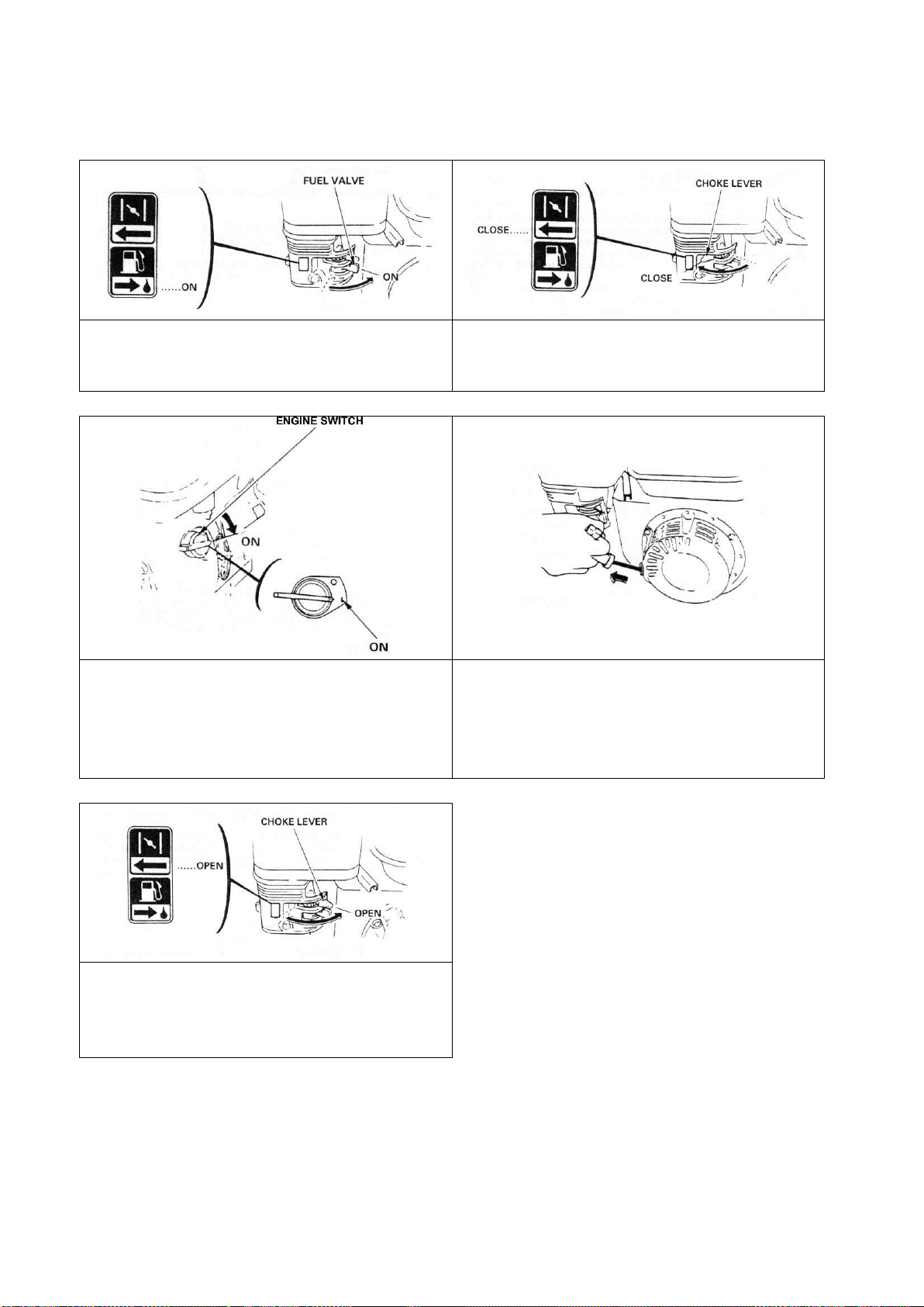
3.3 Starting the machine
Turn the fuel valve to the ON position. Fully
press the dead-man handle against the main
handle.
Move the choke lever to the CLOSED position.
NOTE: do not use the choke if the engine is
warm or the air temperature is high.
Move the throttle control lever slightly to the
left. Put the engine switch on ON.
Pull the starter grip lightly until you feel
resistance, then pull briskly.
CAUTION: Do not allow the starter grip to
snap back against the engine. Return it gently
to prevent damage to the starter.
As the engine warms up, gradually move the
choke lever to the OPEN position.
Position the throttle control lever for the
maximum engine speed.
To stop the engine, release the dead-man handle, move the throttle control lever fully to the right,
then turn the engine switch to the OFF position. Turn the fuel valve to the OFF position.
CAUTION: when the machine is switched off, the tools will continue turning slowly to complete stop.
Be therefore very careful to avoid injuries.
VERS.2015.04.27 CT 901 MP_MAN_EN
14
4 TRANSPORT AND STORING
4.1 Securing for transport
Before transporting the machine, always remove the blades and the plate.
4.2 Transport procedure
Conform yourself to work regulations, in order to transport the machine safely. To help you
transport the machine, you can remove the transport tube from under the handle and located in the
front hole of the machine (see picture below).
To lift the machine, use the lifting eye. Make sure that your lifting device is securely fastened to the
lifting eye.
4.3 Long period of inactivity
If the machine is not going to be used for a long period, completely clean the machine and
disassemble the tools. The storage site must be clean, dry and at a constant temperature.

VERS.2015.04.27 CT 901 MP_MAN_EN
15
5 OPERATING THE MACHINE
5.1 Site of work
Remove from the site anything, which might hinder the working procedure!
Make sure the site is sufficiently well lit!
Make sure you have a continual adequate view of the working area so you can intervene in the
working process at any time!
Keep other staff out of the area, so you can work securely.
5.2 Preparing the site
Prepare the concrete as for manual trowelling. Assure a well levelled surface (we recommend the
use of a beam or better a vibrating screeder). When slab has set sufficiently firm so that the
operator can walk on it, leaving only a slight impression (approx.3mm), it is ready for the floating
operation.
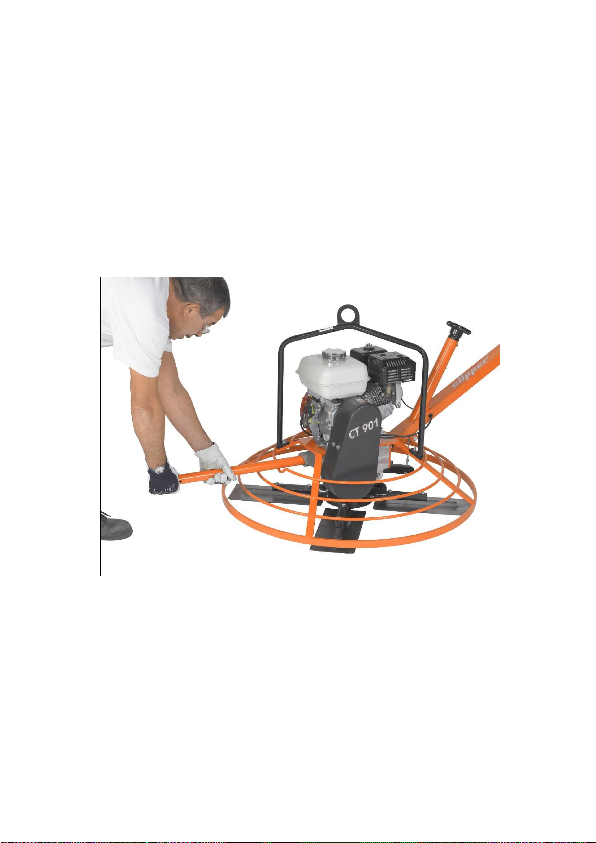
5.3 Floating and finishing operation
To use the machine correctly, you must face it with the two hands on the handle.
Handling the machine
Operate the machine from right to left as shown in the following drawing:
To move the machine:
Forward (I on the following drawing), turn the handle clockwise.
Backward (II), turn the handle counterclockwise.
To the left (III), pull up the handle.
To the right (IV), push down the handle.

VERS.2015.04.27 CT 901 MP_MAN_EN
16
Tilting the blades
Floating the slab is done with the blades nearly flat on the surface of the concrete; however it is
recommended that the blades are just slightly tilted to avoid the suction and drag created in normal
operation of float blades on wet concrete. For the finishing operation, tilt the blades. Start with a
small pitch of 4 to 6 mm. After each finishing pass, continue to tilt blades.
Depression or high spot
To fill a depression or cut down a high spot, simply move the machine back and forward over the
area until the desired surface is obtained.
IMPORTANT: Do not allow the machine to stand in one spot on wet concrete –remove the
machine from the slab when it is not used.
CAUTION: when the machine is switched off, the tools will continue turning slowly to complete stop.
Be therefore very careful to avoid injuries.

VERS.2015.04.27 CT 901 MP_MAN_EN
17
6 MAINTENANCE AND SERVICING
6.1 Maintenance of the machine
To ensure a long-term quality from the use of the CT901MP, please follow the maintenance plan
below:
Begin of the day
During the changing of tool
End of the day
or more often if required
Every week
After a fault
After a damage
Whole machine
Visual control (general aspect,
water tightness)
Clean
Surface of blades or plate
Clean
Tension of the blade
Check
Engine housing
Clean
Reachable nuts and screws
Tighten up
Maintenance of the machine
Always perform the maintenance with the machine switched off and the tools idle.
Lubrication
The CT901MP uses life-lubricated bearings. Therefore, you don’t need to lubricate the machine at
all.
Control and change of the belt
To control the tension of belts, open the belt guard, and push on the belts. You should be able to
gape the belt as thick as a finger. If the tension is incorrect, adjust the belt tension by stalling the
engine. Make sure that the pulleys are aligned before tightening the mounting nuts from the engine.
To change the belt, open the housing, remove the old belt and install a new on the pulleys.
Make sure that the pulleys are aligned before tightening the mounting nuts from the engine. After
the control or change the belts, always reassemble the belt guard.
Cleaning of the machine
Your machine will last longer if you clean it thoroughly after each day of work, especially engine and
blades or pan.
6.2 Maintenance of the engine

VERS.2015.04.27 CT 901 MP_MAN_EN
18
Regular service period
Perform at every indicated month or
operating hour interval, whichever comes
first
Each use
First month or 20 hours
Every 3 months or 50 hours
Every 6 months or 100 hours
Engine oil
Check level
Change
Air cleaner filter
Check
Clean
Fuel strainer cup
Clean
Spark plug
Check-Clean
Fuel line
Check (Replace if necessary)
Every 2 years
Engine oil
To change the oil,
Remove the oil filler cap/dipstick and
drain bolt.
Allow the oil to drain completely.
Dispose of used engine oil in a
manner that is compatible with the
environment. We suggest you to take
used oil in a sealed container to your
local recycling centre or service
station for reclamation. Do not throw it
in the trash, pour it on the ground or
down in a drain.
Reinstall the drain bolt, and tighten it
to 18 N.m.
Fill the crankcase with the engine oil
to the outer edge of the oil filler neck.
Reinstall the filler cap/dipstick.

VERS.2015.04.27 CT 901 MP_MAN_EN
19
Air cleaner
To service the air cleaner filter, follow
these instructions:
Remove the nut, air cleaner cover and
wing nut.
Remove the pre air cleaner elements
and separate them.
Carefully check both elements for
holes or tears and replace if damaged.
Paper element: tap element lightly
several times on a hard surface to
remove excess dirt or blow
compressed air lightly through the
filter from the inside out. Never brush
the dirt off; brushing will force dirt into
the fibres.
Foam element: clean in warm soapy
water, rinse and allow to dry
thoroughly. Dip the element in clean
engine oil and squeeze out all the
excess. The engine will smoke during
initial start-up if too much oil is left in
the foam.
Shine a light through the elements,
and inspect them carefully. Reinstall
the elements if they are free of holes
and tears.
Fuel strainer cup
To service fuel strainer cup, follow these
instructions:
Turn off the fuel valve and remove the
strainer cup.
Clean the strainer cup with solvent.
Install the O-ring and strainer cup.
Tighten the strainer cup to 4N.m.
VERS.2015.04.27 CT 901 MP_MAN_EN
20
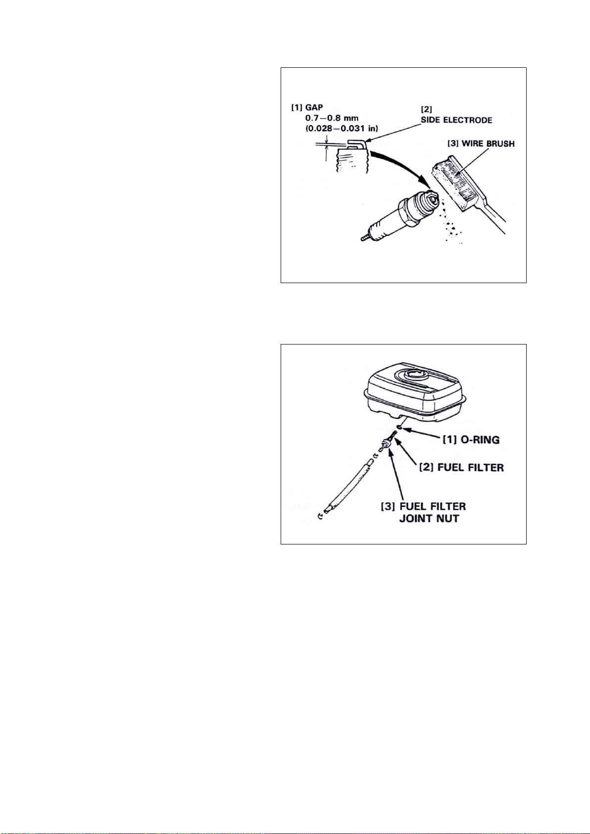
Spark plug
To service the spark plug, follow these
instructions:
Visually inspect the spark plug.
Discard the plug if the insulator is
cracked or chipped.
Remove carbon or other deposits with
a stiff wire brush.
Measure the plug gap with a wire-type
feeler gauge. If necessary, adjust the
gap by bending the side electrode.
Make sure the sealing washer is in
good condition; replace the plug if
necessary.
Install the plug fingertight to seat the washer, then tighten with a plug wrench (an additional
½ turn if a new plug) to compress the sealing washer. If you are reusing a plug, tighten 1/8-
1/4 turn after the plug seats.
Fuel line
To service the fuel line, follow these
instructions:
Drain the fuel into a suitable container,
and remove the fuel tank.
Disconnect the fuel line, and unscrew
the fuel filter from the tank.
Clean the filter with solvent, and
check, that the filter screen is
undamaged.
Place the O-ring on the filter and
reinstall. Tighten the filter to 2N.m.
After reassembly, check for fuel leaks.
Further maintenance
For further maintenance, please contact the nearest engine maintenance centre
This manual suits for next models
1
Table of contents


