LINETROLL 110E/110Eµr User Guide February 2010 Page 3 of 16
1. LINETROLL 110E/110Eµr
OVERVIEW
LINETROLL 110E(110E) is a line
mounted fault indicator for local
indication.
LINETROLL 110Er(110Er) has the
same functionality as the 110Eu but has an
integrated radio that communicate with a
pole-mounted device named Collector
(CmT-110C, -115C or others) that can be
interfaced to a SCADA-RTU or a
communication device by means of dry
relay contacts or serial-port for remote
indication of faults.
Unless especially mentioned, all the
following information is valid for both
110Eµ and 110Eµr.
It is a single phase unit, but as they
normally are used in groups of 3, to fully
cover different fault configurations that
may occur, they are delivered as kit of
3 units each package.
It is a Fault Passage Indicator; detects
down-streams fault in OH-distribution
network; short circuit and earth fault if the
network provide sufficient earth fault
current.
The indicators are placed at strategic
locations along the line such as after
branching points and sectionalisers. It
mounts directly on the high voltage
conductor.
Live line mounting is easily and rapidly
done with a grip-all clamp Hot-Stick.
Upon fault sensing, all indicators installed
in the faulty phase(s) between the feeding
substation and the fault will operate. The
indicators placed behind the fault or in the
non-damaged phase(s) remain idle.
Upon detecting a fault on the line, the
indication by means of an intermittent
LED- flash (3 red LED’s and 1 amber LED
indication for permanent fault and one
Green LED for a transient faults).
This LED-flash can be seen within 100-200
metres distance. The lens of the indicator
allows for uniform 360 degrees
monitoring.
LINETROLL 110Er provides fast fault
location enabling reduction in outage
times. This represents enhanced service to
the customers thereby improving the
utilities image.
Another important aspect of using fault
indicators is that unnecessary operations of
circuit breakers and sectionalisers to locate
the fault are avoided. This way the
indicators help reduce wear and tear as
reclosing cycle causes stress to the
switchgear.
2. FUNCTIONAL
DESCRIPTION
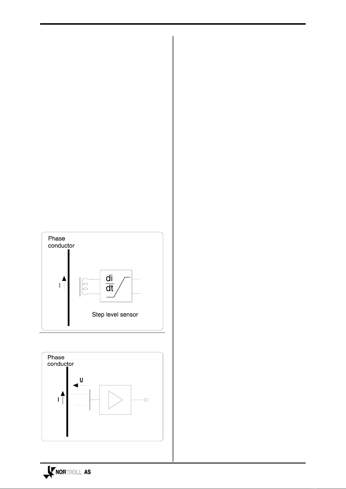
LINETROLL 110Econtinuously
monitors the line voltage and phase
current, the sources of information it needs
to operate. The unit is fully self contained,
no external transformers or connections are
required.
During normal line conditions; the 110E
does not flash.
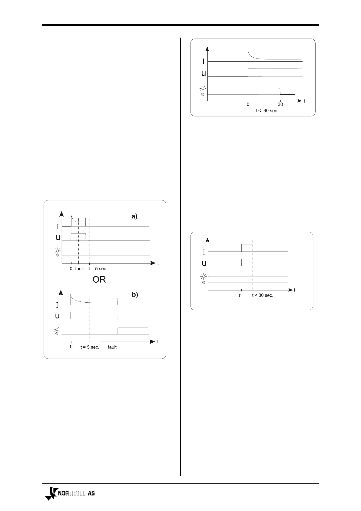
The indicator is looking for a specific
sequence of line conditions to happen
before it starts indicating locally and
remotely. The general sequence is as
follows:
A. The line should be energised (voltage
or current present) for at least 5
seconds.
B. The line current should increase
instantaneously by the amount of a user
set value (the step level), or exceed a
threshold value.
C. The line should be de-energised.
voltage or current not present (optional)