manuals.online logo
Brands
  1. Home
  2. •
  3. Brands
  4. •
  5. Notifier
  6. •
  7. Smoke Alarm
  8. •
  9. Notifier HPX-751 User manual

Notifier HPX-751 User manual

N500-59-00 1 I56-1250-05R
Notier 12 Clintonville Rd, Northford, CT 06472-1653 Phone: (203)484-7161
Before Installing
This detector must be installed in compliance with the
control panel system installation manual. The installation
must meet the requirements of the Authority Having Juris-
diction (AHJ). Detectors offer maximum performance when
installed in compliance with the National Fire Protection
Association (NFPA); see NFPA 72.
General Description
The HPX-751 Smoke Detector uses a small air intake fan
and a high density replaceable lter. Air and smoke are
drawn into a photoelectric sensing chamber while airborne
particulate and water mist are removed. The addressable-
analog detector transmits an analog representation of
smoke density over a communication line to a control
panel. Rotary decade switches are provided for setting the
sensor’s address. Two LEDs on the sensor are controlled
by the panel to indicate sensor status.
The HPX-751 smoke detector is intended for use in
normal environmental conditions, where dust and oth-
er airborne particulate are present at elevated levels.
These elevated levels tend to cause false alarms and
high maintenance in standard detectors. HPX-751 pro-
vides a protective enclosure for a photoelectric smoke
detector chamber and allows smoke detection in areas
that tended to use exclusively heat detection.
HPX-751 requires compatible addressable communic-
ations to function properly. Connect this detector to
listed-compatible control panels only.
Spacing
Notier recommends spacing detectors in compliance with
NFPA 72. In low air ow applications with smooth ceilings,
space detectors 30 feet apart. For specic information
regarding sensor spacing, placement, and special appli-
cations, refer to NFPA 72 or the System Smoke Detector
Application Guide available from Notier.
HPX-751 Intelligent Photoelectronic Smoke Detector
Installation and Maintenance Instructions
Specications
Operating Voltage Range: 15 to 32 VDC
Detector Current: 230 µA @ 24 VDC (without communication)
285 µA @ 24 VDC (one communication every 5 sec. with LED enabled)
Auxiliary Power Supply Voltage: 15 to 30 VDC ltered; Ripple voltage may not drop below 15 volts.
Auxiliary Power Supply Current –
Peak: 123 mA max.
Average: 27 mA max.
Operating Humidity Range: 10% to 93% Relative Humidity, noncondensing
Operating Temperature Range: 0° to 50°C (32° to 122°F)
Height: 2.8 inches (43 mm)
Diameter: 6.1 inches (155 mm) installed in B710HD
4.0 inches (102 mm) installed in B524FTXE
Weight: 7.3 oz. (207 g)
Compatibility: Backwards compatible with 700 and 500 series products’ protocol
Mounting Base: Requires B710HD (U.S.), B524FTXE (Europe)
N500-59-00 4 I56-1250-05R
© 2001 Notier
Figure 5: Installing detector into base:
1. Grasp the housing with one hand and the cover with
the other. Turn the cover counterclockwise fully (approx.
30 degrees) and remove cover by pulling it away from
detector unit (see Figure 4).
2. Replace with new lter and cover assembly. The cover
is keyed so it ts in place only one way. Turn the cover
clockwise until it stops.
NOTE: The base is equipped with an optional tamperproof
feature which can be used to prevent unintentional removal
of the unit while replacing the lter.
If a clogged lter was the cause of the trouble condition,
normal detector operation should resume automatically
within ve minutes. If the trouble condition persists, the
detector must be returned for repair or replacement.
Installing Detector Into Base
1. Align the detector at a right angle to the base, with the
ve wires and connectors adjacent to the connector re-
ceptacle as shown in Figure 5.
2. Plug the wired connector into the receptacle.
3. Rotate the detector into the base, making sure detector
and base keyed t is lined up. Turn the detector clock-
wise until it snaps into place.
IMPORTANT: HPX-751 will only operate with B710HD/
B524FTXE Mounting Base.
FCC Statement
This device complies with part 15 of the FCC Rules. Operation is subject to the following two conditions: (1) This device may not cause harmful inter-
ference, and (2) this device must accept any interference received, including interference that may cause undesired operation.
Note: This equipment has been tested and found to comply with the limits for a Class B digital device, pursuant to Part 15 of the FCC Rules. These lim-
its are designed to provide reasonable protection against harmful interference in a residential installation. This equipment generates, uses and can
radiate radio frequency energy and, if not installed and used in accordance with the instructions, may cause harmful interferenc󱆢 󴱠󰆡 󱃢󳾡 󳑠󰆡 󹱠
nications. However, there is no guarantee that interference will not occur in a particular installation. If this equipment does cause harmful int 󴱠
ference to radio or television reception, which can be determined by turning the equipment off and on, the user is encouraged to try to correct the inter-
ference by one or more of the following measures:
– Reorient or relocate the receiving antenna.
– Increase the separation between the equipment and receiver.
– Connect the equipment into an outlet on a circuit different from that to which the receiver is connected.
– Consult the dealer or an experienced radio/TV technician for help.
Please refer to insert for the Limitations of Fire Alarm Systems
www.PDF-Zoo.com
456
3
7
8
2
19
0
456
3
7
8
2
19
0
N500-59-00 2 I56-1250-05R
WARNING
HPX-751 is not designed to operate in explosive envi-
ronments.
Wiring Instructions
All wiring must be installed in compliance with the National
Electrical Code, applicable local codes, and any special
requirements of the Authority Having Jurisdiction. Proper
wire gauges should be used. The installation wires should
be color-coded to limit wiring mistakes and ease system
troubleshooting. Improper connections will prevent a sys-
tem from responding properly in the event of a re.
Remove power from the communication line before
installing detectors.
All wiring must conform to applicable local codes, ordi-
nances, and regulations.
1. Wire the sensor base per the wiring diagram, please
see Figure 1.
2. Set the desired address on the sensor address switch-
es, please see Figure 2.
3. Insert 5-wire connector on mounting base into 5-pin
connector on the unit. Install the detector into the sen-
sor base. Push the detector into the base while turning
it clockwise to secure it in place. (Please see Figure 5
and INSTALLING DETECTOR INTO BASE on page 4
for specic directions.
4. After all detectors have been installed, turn on the aux-
iliary power supply, then apply power to the control unit
and activate the communication line.
5. Test the detector(s) as described in the TESTING sec-
tion of this manual.
CAUTION
Dust cover must be removed before the detector can
sense smoke.
Testing
Before testing, notify the proper authorities that the system
is undergoing maintenance, and will temporarily be out of
service. Disable the system to prevent unwanted alarms.
All detectors must be tested after installation and periodi-
cally thereafter. Testing methods must satisfy the Authority
Having Jurisdiction (AHJ). Detectors offer maximum per-
formance when tested and maintained in compliance with
NFPA 72.
The sensor can be tested in the following ways:
A.
Functional: Magnet Test (P/N M02-04-01 or M02-09-
00)
This detector can be functionally tested with a test mag-
net. The test magnet electronically simulates smoke in
the sensing chamber, testing the detector electronics
and connections to the control panel.
1. Hold the test magnet in the magnet test area as
shown in Figure 3.
2. The detector should alarm the panel. Two LEDs on
the detector are controlled by the panel to indicate
sensor status. Coded signals, transmitted from the
panel, can cause the LEDs to blink, latch on, or latch
off. Refer to the control panel technical document-
ation for detector LED status operation and expected
delay to alarm.
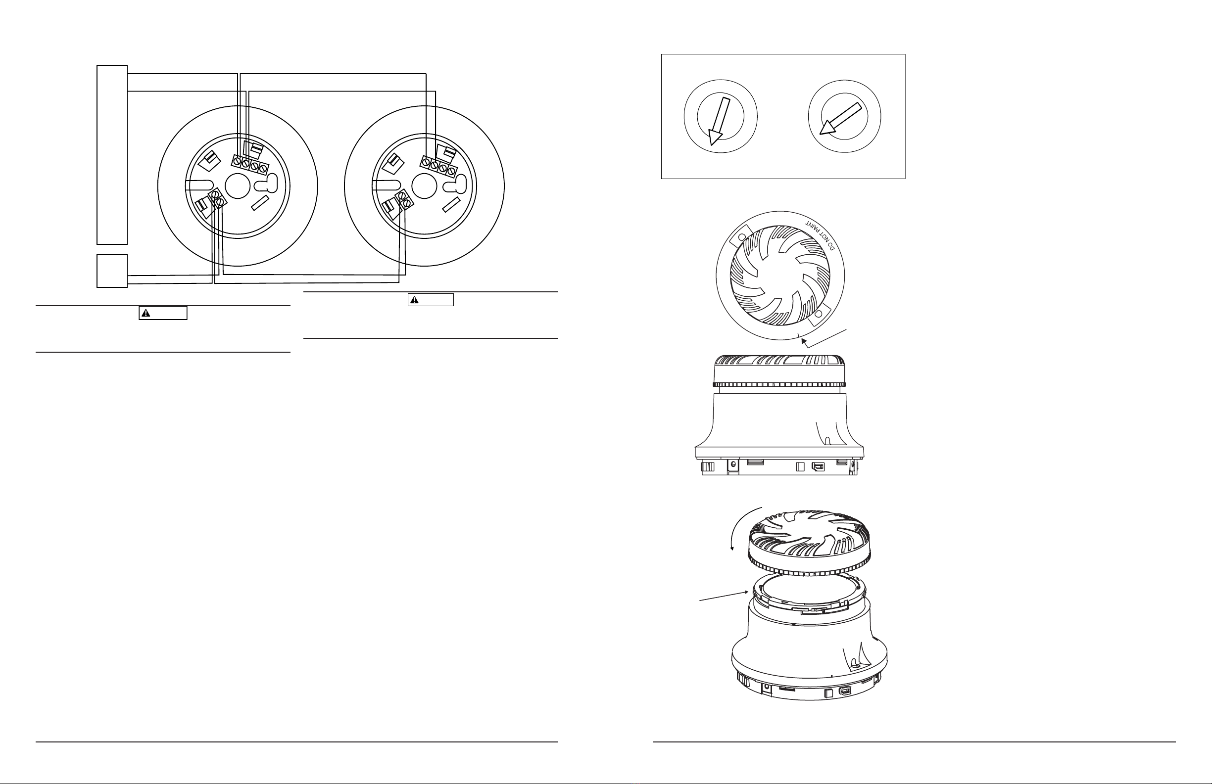
Figure 1. Wiring diagram:
NOTIFIER CONTROL PANEL
AUX.
POWER
SUPPLY
+
+
–
–
AUX+
AUX–
AUX+
AUX–
2(–) 3(RA) 4(S)
1(+)
1(+)
2(–) 3(RA) 4(S)
N500-59-00 3 I56-1250-05R
A78-2460-00
Figure 2. Rotary decade address switches:
Figure 3. Test magnet position:
Figure 4. Replacing the lter cover:
B. Smoke Entry: Aerosol Generator
Aerosol generators for smoke entry testing are available
from a number of third party manufacturers (e.g., Gem-
ini Scientic). Following the manufacturer’s instructions,
apply aerosol until the panel alarms.
A detector that fails any of these tests should be retested.
If the detector still fails any test, have its lter replaced
(see instructions below) and retested. Finally, if the de-
tector continues to fail after replacing the lter, it must be
returned for repair or replacement.
When testing is complete, restore the system to normal
operation and notify the proper authorities that the system
is back in operation.
Cleaning
The unique design of the HPX-751 eliminates the need for
typical detector cleaning. The only maintenance necessary
is replacing the lter, which is signaled by a trouble con-
dition at the panel (see below).
The HPX-751 smoke detector has been designed to max-
imize the amount of time before maintenance is required.
The detector utilizes a replaceable lter that may become
clogged over time. The detector monitors itself to insure
that the lter has not become clogged. Because environ-
mental conditions can vary signicantly, the amount of time
before maintenance could vary signicantly as well. To fully
understand the maintenance requirements of the HPX-751
in its installed location, it is recommended that the following
test program be conducted.
1. Install the HPX-751 detector in the desired location.
2. Connect the detector to the re alarm control panel.
3. Maintain a record for at least 90 days of any mainte-
nance performed on or required by the detector.
4. At the end of the test period, use the record to develop
and schedule maintenance. The HPX-751 should be
serviced at regular intervals to insure that the re alarm
system provides continuous protection.
Replacing the Filter
IMPORTANT:
When the lter becomes too clogged to draw ade-
quate air into the unit, power is automatically cut
from the detector, sending a trouble signal to the
re control panel. After 5 minutes, power is re-
stored to the detector for 72 hours. After 72 hours,
power is cut again and the detector will remain off-
line until the lter is replaced.
Note: The unit has two lters. The replaceable lter is in-
side the cover. A permanent lter is mounted to the unit.
Alignment marks are
provided on the cap
and top of the perma-
nent lter.
Caution: Do Not Loop Wire Under Terminal 1 or 2.
Break Wire To Provide Supervision of Connections.
TEST MAGNET
MARKER
Cover is keyed to
fit into 4 matching
size slots.
www.PDF-Zoo.com

Other Notifier Smoke Alarm manuals

Notifier SD-651 User manual

Notifier

Notifier SD-651 User manual

Notifier AFP-3030 Owner's manual

Notifier

Notifier AFP-3030 Owner's manual

Notifier DHX-502 User manual

Notifier

Notifier DHX-502 User manual

Notifier FSP-751 User manual

Notifier

Notifier FSP-751 User manual

Notifier B610LP User manual

Notifier

Notifier B610LP User manual

Notifier AFP-3030 User manual

Notifier

Notifier AFP-3030 User manual

Notifier SD-851E User manual

Notifier

Notifier SD-851E User manual

Notifier SD-851E User manual

Notifier

Notifier SD-851E User manual

Notifier DHX-501 User manual

Notifier

Notifier DHX-501 User manual

Notifier SDX-751TEM User manual

Notifier

Notifier SDX-751TEM User manual

Notifier FSC-851 User manual

Notifier

Notifier FSC-851 User manual

Notifier FSB-200 User manual

Notifier

Notifier FSB-200 User manual

Notifier CP-651 User manual

Notifier

Notifier CP-651 User manual

Notifier SFP-400B User manual

Notifier

Notifier SFP-400B User manual

Notifier 851 Series User manual

Notifier

Notifier 851 Series User manual

Notifier FSP-851 User manual

Notifier

Notifier FSP-851 User manual

Notifier SD-651A User manual

Notifier

Notifier SD-651A User manual

Notifier INA User manual

Notifier

Notifier INA User manual

Notifier AFP-400 User manual

Notifier

Notifier AFP-400 User manual

Notifier NFX-OPT User manual

Notifier

Notifier NFX-OPT User manual

Notifier FSH-751 User manual

Notifier

Notifier FSH-751 User manual

Notifier CP-651E User manual

Notifier

Notifier CP-651E User manual

Popular Smoke Alarm manuals by other brands

Honeywell FAAST LT Tuning Instructions

Honeywell

Honeywell FAAST LT Tuning Instructions

Wolf-Guard SD-01 user manual

Wolf-Guard

Wolf-Guard SD-01 user manual

usi IoPhic MDS107 instruction manual

usi

usi IoPhic MDS107 instruction manual

Sygonix SY-5040174 operating instructions

Sygonix

Sygonix SY-5040174 operating instructions

System Sensor AGILE Application and installation guidelines

System Sensor

System Sensor AGILE Application and installation guidelines

BRK electronic Dicon M300 owner's manual

BRK electronic

BRK electronic Dicon M300 owner's manual

brennenstuhl Brematic Pro Instructions for use

brennenstuhl

brennenstuhl Brematic Pro Instructions for use

Tyco 601PH quick start guide

Tyco

Tyco 601PH quick start guide

Xtralis XAS-1-US Product guide

Xtralis

Xtralis XAS-1-US Product guide

The Initiator and Company Chick-a-Dee user guide

The Initiator and Company

The Initiator and Company Chick-a-Dee user guide

PSA LIF5800/2 Installation and user manual

PSA

PSA LIF5800/2 Installation and user manual

First Alert SA88B user manual

First Alert

First Alert SA88B user manual

Kidde KN-COSM-BCA user guide

Kidde

Kidde KN-COSM-BCA user guide

Hama 00223843 operating instructions

Hama

Hama 00223843 operating instructions

Nexa EL1313/KD-101LC user manual

Nexa

Nexa EL1313/KD-101LC user manual

Solo 365 user manual

Solo

Solo 365 user manual

Eldes EWF1 user manual

Eldes

Eldes EWF1 user manual

Mircom MIX-2351APA Installation and maintenance manual

Mircom

Mircom MIX-2351APA Installation and maintenance manual

manuals.online logo
manuals.online logoBrands
  • About & Mission
  • Contact us
  • Privacy Policy
  • Terms and Conditions

Copyright 2025 Manuals.Online. All Rights Reserved.