Nova Technology International, LLC Standard Profile Truck Lock Series User manual

Standard Profile Series
Vehicle Restraint Owner’s/User’s Manual
Manual No. NT-0-350 - Rev. May 2021© 2021 Nova Technology International, LLC


1Manual No. NT-0-350 - Rev. May 2021
NOVA Truck Lock™ Standard Prole Manual
PRECAUTIONS......................................................................................................................
OWNER’S/USER’S RESPONSIBILITIES...............................................................................
INSTALLATION INSTRUCTIONS
TYPICAL ARRANGEMENTS.......................................................................................
CAST-IN INSTALLATION.............................................................................................
FLANGE MOUNT INSTALLATION..............................................................................
CONSOLE INSTALLATION.........................................................................................
MANUAL CONSOLE INSTALLATION..............................................................
CONTROL BOX.....................................................................................
OUTSIDE LIGHT.....................................................................................
PNEUMATIC CONSOLE INSTALLATION.........................................................
CONTROL BOX.....................................................................................
OUTSIDE LIGHT.....................................................................................
REAR IMPACT GUARD (RIG) SENSOR (OPTIONAL FEATURE).............................
TEST OPERATION.......................................................................................................
OPERATING PROCEDURES
MANUAL (NO RIG SENSOR)......................................................................................
MANUAL (WITH RIG SENSOR)...................................................................................
PNEUMATIC (NO RIG SENSOR).................................................................................
PNEUMATIC (WITH RIG SENSOR).............................................................................
ROUTINE MAINTENANCE.....................................................................................................
TROUBLESHOOTING............................................................................................................
MANUAL & PNEUMATIC.............................................................................................
LIMIT SWITCH TEST PROCEDURE............................................................................
MAINTENANCE MODE PROCEDURE........................................................................
PARTS......................................................................................................................................
WARRANTY............................................................................................................................
TABLE OF CONTENTS
3
6
8
9
10
11
16
16
16
20
20
20
24
26
38
43
49
53
58
59
59
60
62
66
85

2Manual No. NT-0-350 - Rev. May 2021
NOVA Truck Lock™ Standard Prole Manual
This page intentionally left blank

3Manual No. NT-0-350 - Rev. May 2021
NOVA Truck Lock™ Standard Prole Manual
PRECAUTIONS
Safety-Alert Symbol
The Safety- Alert Symbol is a graphic representation
intended to convey a safety message without the
use of words. When you see this symbol, be alert
to the possibility of death or serious injury. Follow
the instructions in the safety message panel.
DANGERDANGER
The use of the word DANGER signifies the
presence of an extreme hazard or unsafe practice
which will most likely result in death or serious
injury.
WARNING
The use of the word WARNING signifies the
presence of a serious hazard or unsafe practice
which could result in death or serious injury.
CAUTIONCAUTION
The use of the word CAUTION signifies possible
hazard or unsafe practice which could result in
minor or moderate injury.
NOTICE
The use of the word NOTICE indicates information
considered important, but not hazard-related, to
prevent machine or property damage.
SAFETY INSTRUCTIONS
Indicates a type of safety sign, or separate panel on
a safety sign, where safety-related instructions or
procedures are described.
Read and understand the Owner’s/User’s Manual
and become thoroughly familiar with the equipment
and its controls before operating the transport vehicle
restraint.
Never operate a transport vehicle restraint while a
safety device or guard is removed or disconnected.
Never remove DANGER, WARNING, or CAUTION
signs, Placards or Decals on the equipment unless
replacing them.
Figure 1
Do not start the equipment until all unauthorized
personnel in the area have been warned and have
moved outside the operating zone (see Figure 1).
Remove any tools or foreign objects from the operating
zone before starting.
Keep the operating zone free of obstacles that could
cause a person to trip or fall.
Recognize Precautionary Information General Operational Precautions
WARNING: This product can expose you to chemicals including lead, which are known to the State of California to
cause cancer or birth defects or other reproductive harm. For more information go to www.P65Warnings.ca.gov

4Manual No. NT-0-350 - Rev. May 2021
NOVA Truck Lock™ Standard Prole Manual
Operational Precautions
Learn the safe way to operate this
equipment. Read and understand the
manufacturer’s instructions. If you have any
questions, ask your supervisor.
DANGERDANGER
Stay clear of dock leveling device and restraint when
transport vehicle is entering or leaving area.
Do not move or use the dock leveling device and
restraint if anyone is under in front or near it.
Keep hands and feet clear of pinch points. Avoid
putting any part of your body near moving parts.
Do not operate any equipment while under the
inuence of alcohol or drugs.
PRECAUTIONS
WARNING
Chock/restrain all transport vehicles. Never remove
the wheel chocks until loading or unloading is
finished and transport vehicles driver has been given
permission to drive away.
Do not use a broken or damaged restraint device.
Make sure proper service and maintenance
procedures have been performed before using.
If the NOVA Truck Lock™ vehicle restraint does not
operate properly using the procedures in this manual,
enter HORN OVER-RIDE mode by following the
instructions printed on the control box. Contact NOVA
or your local representative for service.

5Manual No. NT-0-350 - Rev. May 2021
NOVA Truck Lock™ Standard Prole Manual
Maintenance Precautions
PRECAUTIONS
WARNING
Always post safety warnings and barricade the
work area at dock level and ground level to prevent
unauthorized use of the unit before maintenance is
complete.
ALWAYS disconnect electrical power source and
ground wire before welding on restraint.
DO NOT ground welding equipment to any electrical
components of the restraint. Always ground to the
restraint frame.
DO NOT grind or weld if hydraulic fluid or other
flammable liquid is present on the surface to be
ground or welded.
DO NOT grind or weld if uncontained hydraulic fluid
or other flammable liquid is present. Stray sparks
can ignite spills or leaks near the work area. Always
clean up the oil leaks and spills before proceeding
with grinding or welding.
Always keep a fire extinguisher of the proper type
nearby when grinding or welding.
DANGERDANGER
Electrical power must be OFF when servicing the
equipment. For maximum protection, use an OSHA*
approved locking device to lock out all power
sources. Only the person servicing the equipment
should have the key to unlock the device.
VEHICLE RESTRAINT SAFETY DECALS
Every 90 days (quarterly) inspect all safety labels,
placards and tags to ensure they are present, easily
seen and legible. Refer to the Parts section of this
publication to identify the location of the safety
items listed below. Call NOVA Technical Service for
replacements.
Page # Item # Description
69 24 Do Not Operate Decal
69 25 Warning Decal
71 21 Warning Decal
71 22 Do Not Operate Decal
71 23 Caution Decal
74, 75 8 No Step Decal
76, 77, 78 5 No Step Decal
81 2 Move On Green Sign
* Refer to OSHA Regulation 1910.146 Conne Space, 1910.147 Lockout/Tagout

6Manual No. NT-0-350 - Rev. May 2021
NOVA Truck Lock™ Standard Prole Manual
1. The manufacturer shall provide to the initial
purchaser and make the following information
readily available to the owners/users and their
agents, all necessary information regarding
Safety Information, Operation, Installation and
Safety Precautions, Recommended Initial
and Periodic Inspections Procedures, Planned
Maintenance Schedule, Product Specifications,
Troubleshooting Guide, Service Parts Listing,
Warranty Information, and Manufacturers Contact
Information.
2. The owner/user should recognize the inherent
dangers of the interface between the loading
dock and the transport vehicle. The owner/
user should, therefore, train and instruct all
operators in the safe operation and use of
the restraining device in accordance with
manufacturer’s recommendations and industry
standards. Effective operator training should also
focus on the owner’s/user’s company policies,
operating conditions and the manufacturer’s
specific instructions provided with the
restraining device. Maintaining, updating and
retraining all operators on safe working habits
and operation of the equipment, regardless of
previous experience, should be done on a regular
basis and should include an understanding and
familiarity with all functions of the equipment.
Owner’s/ user’s shall actively maintain, update and
retrain all operators on safe working habits and
operations of the equipment.
3. When selecting a restraining device, it
is important to consider not only present
requirements but also future plans and any
possible adverse conditions, environmental
factors or usage. The owners/ users shall provide
application information to the manufacturer
to receive recommendations on appropriate
equipment specifications.
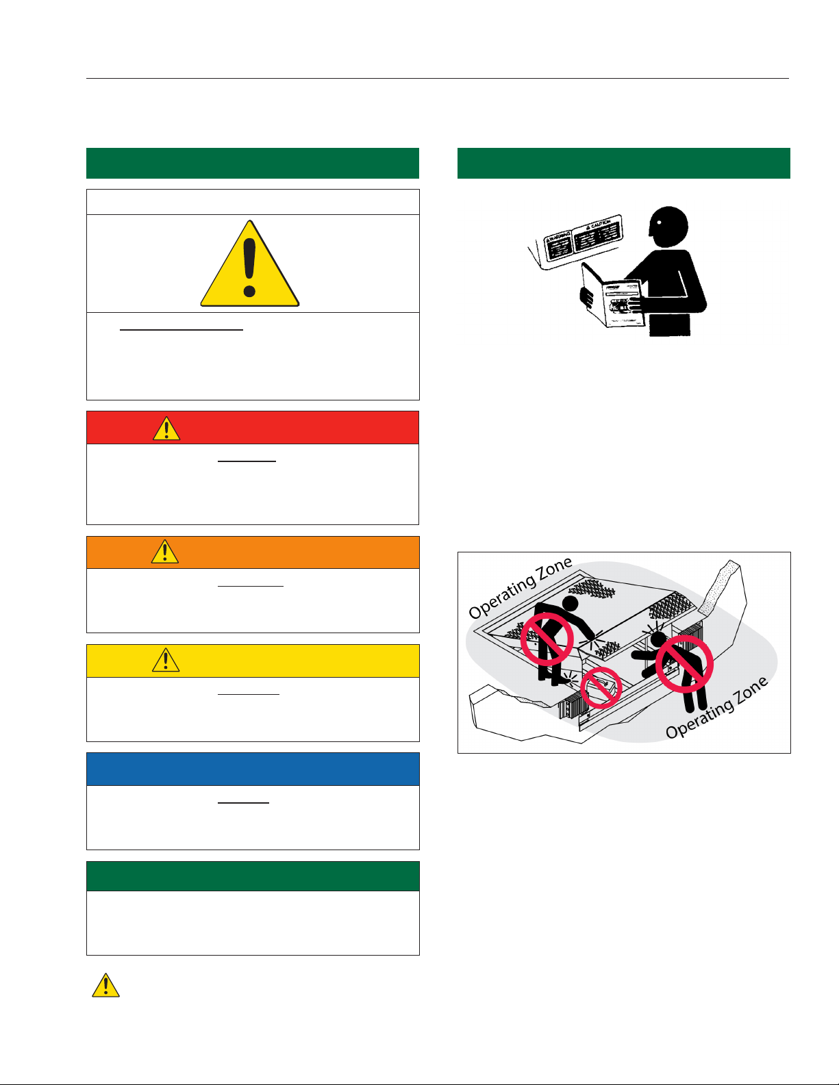
4. The owner/user must see all nameplates,
placards, decals, instructions and posted warnings
are in place and legible and shall not be obscured
from the view of the operator or maintenance
personnel for whom such warnings are intended
for. Contact manufacturer for any replacements.
5. Modifications or alterations of restraining devices
shall be made only with prior written approval from
the original manufacturer. These changes shall
be in conformance with all applicable provisions
of the MH30.3 standard and shall also satisfy all
safety recommendations of the original equipment
manufacturer of the particular application.
6. An operator training program should consist of, but
not necessarily be limited to, the following:
a. Select the operator carefully. Consider the physical
qualifications, job attitude and aptitude.
b. Assure that the operator reads and fully
understands the complete manufacturer’s owners/
users manual.
c. Emphasize the impact of proper operation upon
the operator, other personnel, material being
handled, and equipment. Cite all rules and why
they are formulated.
d. Describe the basic fundamentals of the restraining
device and components design as related to safety,
e.g., mechanical limitation, stability, functionality,
etc.
e. Introduce the equipment. Show the control
locations and demonstrate functions. Explain how
they work when used properly and maintained as
well problems when they are used improperly.
f. Assure that the operator understands nameplate
data, placards and all precautionary information
appearing on the restraining device.
g. Supervise operator practice of equipment.
h. Develop and administer written and practical
performance tests. Evaluate progress during and
at completion of the course.
i. Administer periodic refresher courses. These may
be condensed versions of the primary course and
include on-the-job operator evaluation.
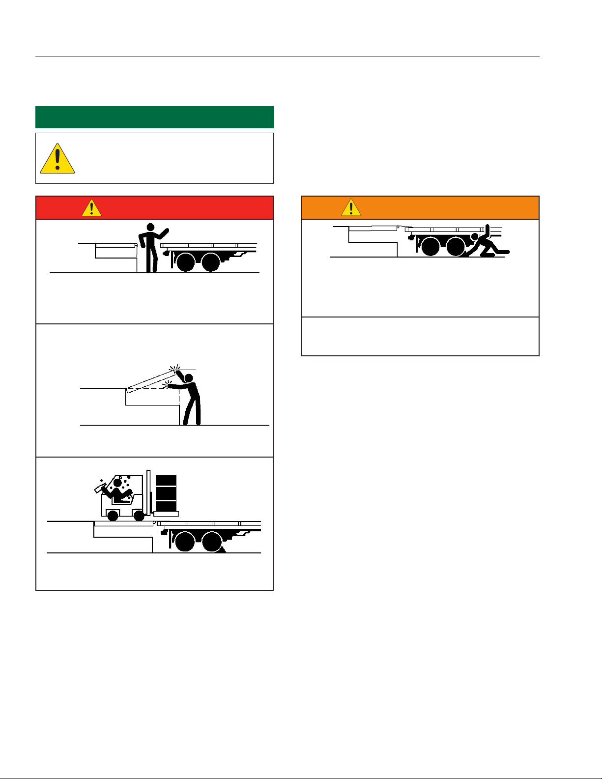
7. It is recommended that the transport vehicle
is positioned as close as practical to the dock
leveling device and in contact with both bumpers.
When an industrial vehicle is driven on or o a
transport vehicle during the loading and unloading
operation, the transport vehicle parking brakes
shall be applied and wheel chocks or restraining
device that provides equal or better protection of
wheel chocks shall be engaged. Also, whenever
possible, air-ride suspension systems should have
the air exhausted prior to performing said loading
and unloading operations.
OWNER’S/USER’S RESPONSIBILITIES

7Manual No. NT-0-350 - Rev. May 2021
NOVA Truck Lock™ Standard Prole Manual
8. When goods are transferred between the loading
dock and a trailer resting on its support legs/
landing gear instead of a tractor fth wheel
or converter dolly, it is recommended that an
adequate stabilizing device or devices shall be
utilized at the front of the trailer.
9. In order to be entitled to the benets of the
standard product warranty, the dock safety
equipment must have been properly installed,
maintained and operated in accordance with
all manufacturer’s recommendations and/
or specied design parameters and not
otherwise have been subject to abuse, misue,
misapplication, acts of nature, overloading,
unauthorized repair or modication, application in
a corrosive environment or lack of maintenance.
Periodic lubrication, adjustment and inspection
in accordance with all manufacturers’
recommendations are the sole responsibility of the
owner/user.
10. Manufacturer’s recommended maintenance
and inspection of all restraining devices shall
be performed in conformance with the following
practices: A planned Maintenance schedule
program must be followed, only trained and
authorized personnel shall be permitted to
maintain, repair, adjust and inspect restraining
devices, and only the use of original equipment
manufacturer parts, manuals, maintenance
instructions, labels, decals and placards of their
equivalent. Written documentation of maintenance,
replacement parts or damage should be kept.
In the event of damage, notication to the
manufacturer is required.
11. Restraining devices that are structurally damaged
shall be removed from service, inspected by a
manufacturer’s authorized representative, and
repaired or replaced as needed or recommended
by the manufacturer before being placed back in
service.
OWNER’S/USER’S RESPONSIBILITIES

8Manual No. NT-0-350 - Rev. May 2021
NOVA Truck Lock™ Standard Prole Manual
DOCK SEAL
350 HOUSING
CONDUIT
(SUPPLIED
BY OTHERS)
CONDUIT
(SUPPLIED
BY OTHERS)
LOWER PULLEY
SWIVEL BRACKET
ASSEMBLY
OUTSIDE UPPER
PULLEY SWIVEL
BRACKET ASSEMBLY
CONTROL BOX
INSIDE POWER
TO CONTROL BOX
OUTSIDE
"CAUTION -
MOVE ON
GREEN"
SIGN
OUTSIDE
LIGHTS
CONSOLE
RAM BAR
FIGURE A—TYPICAL ARRANGEMENT
Figure above shows typical arrangements and functions of major components for the NOVA Truck Lock™ Standard Profile.
When properly installed and operated, the NOVA Truck
Lock™ Standard Prole oers the user substantially
improved dock safety and eciency. Its design is
the result of many years of experience with loading
dock operation. It features an easy to read inside light
system for the dock attendant, “STOP & GO” outside
light system for the truck driver, and a restraining
device to discourage premature or unexpected truck
departure.
INSTALLATION INSTRUCTIONS
TYPICAL ARRANGEMENTS

9Manual No. NT-0-350 - Rev. May 2021
NOVA Truck Lock™ Standard Prole Manual
INSTALLATION INSTRUCTIONS
CAST-IN INSTALLATION
NOTICE
If sensor kit is purchased, install sensor switch
housing prior to pouring concrete. See step 1
in Rear Impact Guard (RIG) Sensor Installation
section.
Step 1 (Concrete): Determine exact location of
restraint ram housing per Figure B. Dimensions are
from face of dock bumpers. If bumpers are not yet
installed, add thickness of bumpers when measuring
from the dock face.
12"
FROM
BUMPER
FACE
20"
20"
20"
PLUM BOB FROM
FRONT FACE OF
BUMPERS
C
L
OF DOCK
OR DOCKLEVER
IF CRACKS ARE PRESENT IN "CRACK-FREE ZONE", CONTACT
NOVA TECHNOLOGY BEFORE PROCEEDING TO NEXT STEP
"CRACK-FREE ZONE"
10"
FIGURE B—RAM HOUSING LOCATION
NOTICE
To ensure successful installation, center of 10”
diameter hole MUST BE 12” away from DOCK
BUMPER FACE. For decline docks, if 5% decline
is present, housing must be moved an additional
1” away from DOCK BUMPER FACE and 1” for
every percent thereafter.
Step 2 (Concrete): Core drill (auger, posthole
digger, etc.) a 10 inch diameter hole minimum of 30
inches deep. Excavate hole back to dock wall. The
nal shape of completed excavation depends on
driveway surface. See Figure C.
FIGURE C—COMPLETED EXCAVATION
Step 2 (Non-Concrete): For non-concrete
driveway surface, an area as shown in Figure D
must be cut out. This yields a much more substantial
base since asphalt is subject to some movement
climatically. See Figure D for placement of rebars
when installing in non-concrete drive. Rebar must be
bolted to concrete foundation using supplied fasteners.
If foundation is not concrete, call Nova Technology.
The housing may be welded to the middle two rebars
to help hold and stabilize housing during concrete
pour.
10"
24"
36"
4X 5"
2X 6"
2X 3"
FIGURE D—REBAR PLACEMENT
DANGERDANGER
Post safety warnings and barricade work area,
at dock level and at ground level, to prevent
unauthorized use of the dock position.

10 Manual No. NT-0-350 - Rev. May 2021
NOVA Truck Lock™ Standard Prole Manual
INSTALLATION INSTRUCTIONS
NOTICE
Ram housing must be “plumb” left to right. The
bottom of the front support must be flush with
top of drive surface. It is very important to verify
the distance from bumper face to back edge of
ram is 10”. See Figure E.
FIGURE F—RAM HOUSING LOCATION
FIGURE G—FLANGE HOUSING HOLE DEPTH
10"
POURED
CONCRETE
BUMPER
FOUNDATION WALL
FRONT SUPPORT MUST REST ON
ORIGINAL CONCRETE DRIVE
DOCK FACE
FIGURE E—RAM HOUSING FROM BUMPER
Step 3: Support housing in augured hole and secure
with concrete. See Figure E.
NOTICE
Agitate concrete after pouring to prevent air
pockets underneath housing.
FLANGE MOUNT INSTALLATION
Step 1 (Concrete): Determine exact location of
restraint ram housing per Figure F. Dimensions are
from face of dock bumpers. If bumpers are not yet
installed, add thickness of bumpers when measuring
from the dock face.
12"
FROM
BUMPER
FACE
20"
20"
20"
PLUM BOB FROM
FRONT FACE OF
BUMPERS
C
L
OF DOCK
OR DOCKLEVER
IF CRACKS ARE PRESENT IN "CRACK-FREE ZONE", CONTACT
NOVA TECHNOLOGY BEFORE PROCEEDING TO NEXT STEP
"CRACK-FREE ZONE"
10"
Step 2: Core drill hole (auger, posthole digger, etc.)
minimum of 24 inches deep. A 10” diameter hole
must be used for ange mount to ensure correct edge
spacing.
24"
10''
Step 3: Locate Flange housing sheath so Ram bar
is 10” back from bumper face. See Figure E. Make
sure housing sheath bottom is 24” from top of concrete
surface. Backll with housing sheath and cover in
place. See Figure G.

11Manual No. NT-0-350 - Rev. May 2021
NOVA Truck Lock™ Standard Prole Manual
INSTALLATION INSTRUCTIONS
NOTICE
Use (7) 5/8 x 5 inch orange tip wedge bolt
(Supplied by NOVA). Wedge bolt is a heavy duty
self-tapping anchor. Meets AISI 1020/1040 carbon
steel. Blue tip wedge bolts are not allowed.
Refer to Power Fasteners, Inc. Wedge Bolt
#7221. Nova P/N 40-0-112.
Step 4: Place housing in sheath and insert orange
tip wedge bolts. To insert wedge bolt, drill a 5/8 inch
hole through concrete in rst location. Clean out hole
with compressed air. Drive wedge bolt into prepared
holes until clamping the mounting plate to concrete.
Do not exceed 75 ft-lbs of torque. DO NOT insert a
wedge bolt in any holes in which reinforcing rod is
encountered. If rebar is encountered, use a 5/8 inch
diameter x 5 inch long Powerbolt. One Powerbolt is
included with each restraint. If more than 1 bolt hits
rebar consult factory at 800-236-7325.
CONSOLE INSTALLATION
NOTICE
Verify there are no obstructions on outside of
building which would interfere with cable run
between control console and ram housing.
Position control console so that activation
cable clears dock bumpers. Also, verify there is
adequate clearance for future installation of dock
seals or shelters. See Figure H.
DOCK SEAL
TRUCK LOCK
DOCK LEVELER
UNOBSTRUCTED ZONE
FIGURE H—CLEARANCE FOR SEALS AND SHELTERS
Step 1: Remove cover from control console by
removing four 3/8” x 1/2” bolts. If metal building
support is required as per survey sheet, follow those
instructions for correct installation.
Step 2: Temporarily place control console (with
cover removed) against inside wall in desired location.
Verify the console is parallel with the wall. Mark the
four mounting holes for the console (two on wall and
two on oor) as well as the 1” diameter cable exit hole.
See Figure I.
1
4
"
1"
MARK HOLE
LOCATIONS
ON WALL
FIGURE I—PULLEY BRACKET HOLE LOCATIONS

12 Manual No. NT-0-350 - Rev. May 2021
NOVA Truck Lock™ Standard Prole Manual
INSTALLATION INSTRUCTIONS
Step 3: First, drill the 1” diameter cable exit hole
through the wall from the inside at the location marked
in Figure I. Replace bracket and check alignment of
the 1” hole per Figure K, then drill mounting holes.
NOTICE
To prevent outside concrete wall from chipping,
drill a 1/2” pilot hole first. If drilling into a block
wall, loose insulation, etc., sleeve the hole with a
section of 3/4” conduit.
1
4
"
4"
1
2
"
2"
1" CABLE EXIT HOLE
FIGURE K—CABLE EXIT HOLE LOCATION
NOTICE
Use truss head expansion bolts, toggle bolts
or through bolts as appropriate. Bolts and
fasteners supplied by installer.
Step 5: Align the top of the pulley with the center
of the 1” hole in the wall and mount the upper swivel
bracket assembly to the exterior wall. See Figure J &
L.
UPPER PULLEY SWIVEL
BRACKET ASSEMBLY
4 FASTENERS SUPPLIED BY OTHERS
FIGURE L—FASTEN UPPER PULLEY SWIVEL BRACKET
FLANGE MOUNT ONLY Step 6: Insert 1/2-
13x4-1/2” bolt through hole furthest from dock side and
the tail section. Place tail section in place up to dock
wall. Mark location and pivot up around the 1/2” bolt.
Insert 3/8-16x1” ange head bolts and ange nuts
in slot to stop travel of the tail section away from the
dock. Pivot down and insert other 1/2-13x4-1/2” bolt
through hole closer to the dock. Tighten both nylock
nuts. See Figure M.
NOTICE
Recessed building wall or dock foundation wall
may require a special bracket as per your survey
sheet.
FIGURE M—SECURING TAIL SECTION TO HOUSING
A
A
CABLE MUST RUN ON PULLEYS
OUTSIDE WALL
CONTROL CONSOLE
UPPER PULLEY SWIVEL ASSEMBLY
CABLE
CABLE MUST NOT RUB ON
WALL MAERIAL
FIGURE J—INSIDE & OUTSIDE PULLEY TRACKING
NOTICE
Proper alignment of the Inside and Outside
pulleys is required to prevent damage to the
cable from abrasion with the outside wall. See
Figure J.
Step 4: Replace console pole and conrm alignment.
Then drill mounting holes and mount control console
on inside of building wall.
CAST-IN ONLY Step 6: Bolt E.O.D. extension
bracket to dock side of ram housing with supplied
bolts. E.O.D. extension bracket should touch dock face
when positioned properly.

13Manual No. NT-0-350 - Rev. May 2021
NOVA Truck Lock™ Standard Prole Manual
INSTALLATION INSTRUCTIONS
NOTICE
Make sure cable is tracking in pulleys, cable
should run over pulley on housing.
Step 7: Mount lower pulley assembly to foundation
directly beneath upper pulley assembly. In northern
climates, where driveway heaving (freezing) is
possible, the lower pulley swivel bracket may be
installed 2-3” above the drive. See Figure N.
UPPER PULLEY SWIVEL
BRACKET ASSEMBLY
LEVEL
CONDUIT LENGTH (DISTANCE BETWEEN
UPPER AND LOWER PULLEY SWIVEL
ASSEMBLY PLUS 2 3/4")
LOWER PULLEY SWIVEL
BRACKET ASSEMBLY
CONDUIT LENGTH (A SLIGHT PITCH
MAY BE DESIRED TO ALLOW WATER
TO DRAIN) (DISTANCE BETWEEN UPPER
AND LOWER PULLEY SWIVEL ASSEMBLY
PLUS 2 3/4")
LEVEL
FIGURE N—LOWER PULLEY LOCATION
NOTICE
Leave adjustment nut on lower pulley swivel
assembly in the middle during restraint
assembly. See Figure O.
LEAVE ADJUSTMENT NUT IN
THE MIDDLE FOR NOW
LOWER PULLEY SWIVEL
BRACKET ASSEMBLY
FIGURE O—ADJUSTMENT ON LOWER PULLEY
Step 8: Remove ram from housing and carefully
pour in 2 quarts (8 cups) of NOVA Juice-E. See Figure
P.
POUR NOVA JUICE
INTO RAM BAR
OPENING IN HOUSING
FIGURE P—LOCATION WHERE TO POUR NOVA JUICE
Step 9: Measure distance between conduit collar on
upper pulley bracket and conduit collar on lower pulley
swivel bracket and add 2-3/4”. Cut a piece of ¾” thin
wall conduit to these lengths. See Figure Q.
THIS DISTANCE PLUS
2-3/4" WHEN LOWER
PULLEY SWIVEL BRACKET
IS RETRACTED
THIS
DISTANCE
SET SCREW
FIGURE Q—DISTANCE BETWEEN PULLEYS

14 Manual No. NT-0-350 - Rev. May 2021
NOVA Truck Lock™ Standard Prole Manual
INSTALLATION INSTRUCTIONS
Step 10: Measure distance from conduit collar on
lower pulley to conduit collar on extension bracket and
add 2-3/4”. Cut ¾” thin wall conduit to length as above.
Slide end into tube on lower pulley. Thread cable
through lower and upper pulley assemblies. Allow
free cable end to stick out of conduit at top pulley. Do
not attempt to feed through building wall at this time.
Slide end of conduit into conduit collar on ram housing
and secure with set screw. See Figure Q.
Step 11: Route ram cable around top of upper
outside pulley, into building through hole in wall, and
over the pulley. See Figure R.
CABLE
THROUGH WALL
TO CONSOLE
PULLEY
CONDUIT
UPPER PULLEY
SWIVEL BRACKET
ASSEMBLY
FIGURE R—CABLE ROUTED THROUGH PULLEY
Proceed to one of the following Console
installation instructions:
Manual Console Installation: Page 14
Pneumatic Console Installation: Page 18
NOTICE
A step using the manual Truck Lock™ is noted
with the letter “M” behind the step number.
Example: 5M.
A step using the pneumatic Truck Lock™ is
noted with the letter “P” behind the step number.
Example: 4P.

15Manual No. NT-0-350 - Rev. May 2021
NOVA Truck Lock™ Standard Prole Manual
This page intentionally left blank

16 Manual No. NT-0-350 - Rev. May 2021
NOVA Truck Lock™ Standard Prole Manual
INSTALLATION INSTRUCTIONS
Step 12M: Raise handle to full up position. Make
sure upper limit switch lever is contacting Activation
Handle Tube. Pull cable tight and attach to spring
using cable clamp. Run excess cable down center of
spring, exiting on right side of handle. Cut o cable
ush with bottom of spring. See Figure S.
CUT OFF EXCESS CABLE
ACTIVATED LIMIT SWITCH
HANDLE IN FULL
UP POSITION
FIGURE S—SETTING UP MANUAL CONSOLE
Step 13M: Determine location of outside light on
exterior of building. Light must be on truck driver
side of dock door (Right side when facing dock from
outside). Verify location of light will not interfere with
the future installation of dock shelters or seals. Drill
hole through wall at approximate center of light. Feed
wire from light through hole in wall and ax light to
wall.
2-3"
FIGURE T—MOUNTING CONTROL BOX
Step 15M: Route wires from outside light to inside
control box through the grommeted hole in the bottom
of the box. See Figure U. Cut to length and connect to
terminal strip. See Figure V & W.
GREEN
LIGHT
RED WIRE
FROM LIGHT BOX
BLACK WIRE
FROM LIGHT BOX
RED WIRE FROM LIGHT BOX
(MARKED WITH "GREEN LIGHT" TAG)
RL
-V
GL
RED LIGHT
GREEN LIGHT
OUTSIDE LIGHT COVER
TO
CONTROL
BOX
OUTSIDE LIGHT WIRING
FIGURE V—OUTSIDE LIGHT WIRING
MANUAL CONSOLE INSTALLATION
(See Page 18 for pneumatic console
installation)
FIGURE U—ROUTE WIRES THROUGH GROMMETS
HORN
OPTIONAL
RIG SENSOR
WIRES
POWER CORD
OUTSIDE LIGHT
WIRES
CONTROL BOX
Step 14M: Mount control box to wall 2” to 3” above
console using fasteners supplied by installers. See
Figure T.
OUTSIDE LIGHT

17Manual No. NT-0-350 - Rev. May 2021
NOVA Truck Lock™ Standard Prole Manual
INSTALLATION INSTRUCTIONS
BLACK WIRE FROM LIGHT BOX
RED WIRE
FROM LIGHT BOX
RED WIRE FROM LIGHT BOX
(MARKED WITH "GREEN LIGHT" TAG)
DIN RAIL
CIRCUIT BREAKER
POWER SUPPLY
BLACK WIRE FROM
OPTIONAL RIG SENSOR
WHITE WIRE FROM
OPTIONAL RIG SENSOR
FIGURE W—WIRING CB-12 CONTROL BOX
Step 16M: Insert plug into wall receptacle or hard
wire per local codes.
NOTICE
Fifteen (15) NOVA Truck Lock™control boxes
can be connected to one (1) 15 amp branch
circuit breaker per 1999 National Electric Code,
assuming no other loads on circuit.
Step 17M: Connect the (2) three-wire electrical
cables from the control box to the limit switches, one
mounted on the cover and the other mounted on the
top of the slide pole. See Figure X.
INSIDE OF CONSOLE COVER
LIMIT SWITCH 1
SLIDE POLE
LIMIT SWITCH 2
FIGURE X—CONNECTING LIMIT SWITCHES
Step 18M: Replace cover on control console and
secure with (4) 3/8”x1/2” bolts and star lock washers.
Slide plastic grip on to activation handle. See Figure Y.
NOTICE
Secure wires from the control box out of the
way from getting tangled in activation handle, or
counterweight assembly once console cover is
replaced.
ACTIVATION HANDLE
PLASTIC GRIP
CONTROL
CONSOLE
COVER
3/8"X1/2" HH BOLT
STAR
LOCK
WASHER
FIGURE Y—REPLACE CONTROL CONSOLE COVER
CAUTIONCAUTION
All electrical work —including the installation
of the disconnect panel, control panel, and final
connections to the pit junction box — must be
performed by a certified electrician and conform
to all local and applicable national codes.

18 Manual No. NT-0-350 - Rev. May 2021
NOVA Truck Lock™ Standard Prole Manual
INSTALLATION INSTRUCTIONS
Step 19M: Move activation handle down into
“RESTRAIN” position which will raise restraint ram
outside. Adjust ram height by turning nut on lower
pulley assembly. See Figure Z.
LOWER PULLEY SWIVEL
BRACKET ASSEMBLY
ADJUST NUT
FIGURE Z—ADJUSTMENT ON LOWER PULLEY SWIVEL
BRACKET
Step 20M: Tighten cable until entire guide height
hole is showing. See Figure AA.
ENTIRE GUIDE HEIGHT
HOLE IN RAM BAR IS
VISIBLE
RAM BAR
FIGURE AA—GUIDE HEIGHT HOLE SHOWN
NOTICE
Visually check to ensure Ram bar is at correct
height after adjustments are made.
CAUTIONCAUTION
Concrete must be cured prior to performing Step
19M. If concrete has not cured, the cable tension
of Step 19M will cause the Truck Lock™ to move
out of position.
Table of contents
Other Nova Technology International, LLC Lifting System manuals