Novacom CDCS ION User manual

ELECTROSTATIC FIELD METER
CDCS ION
www.novacom-vacuum.com
INSTRUCTIONS

TECHNICAL INFORMATIONS
WARNING
SUMMARY
2
Reference
Detection range
Response
time
Measure-
ment
accuracy
Temperature
accuracy Communication protocol Cable
length Weight (g)
Electrostatic
potential test
mode
Ion balance
mode
CDCS ION 0 ~ ± 60kV 0 ~ ± 200V <100 ms ± 5% ± 1,5
CAN Communication
(RS485 optional
communication function)
1m 147
In order to ensure a safe operation and achieve the best performance of the product, please follow the precautions and
instructions of this manual.
- Do not hit the sensing part of the sensor
- Do not use in water or with wet hands
- When replacing parts, please use original parts
- Turn off power after use and take out the battery if not used during an extended period of time
Please keep this manual for reference at any time.
1. Overview of the static eld meter
2. Drawing and spare parts
2.1. Display screen diagram
2.2. Spare parts
3. Product features
4. Product parameters and instructions
4.1. Performance parameters
4.2. Mode and detection range
4.3. Network port PIN denition
4.4. Operation method
5. Battery replacement
6. Communication protocol
6.1. Description of the CAN protocol
7. Maintenance
1. Devices body
2. Display screen
3. Power button
4. HOLD button
5. Mode button*
6. Status indicator
7. Communication port
8. Jack wire connection
9. Restart button
10. Battery cover
11.Test window
12. Red pilot light
*IS NOT ACTIVE ON THIS MODEL
PLAN

1. OVERVIEW OF THE STATIC FIELD METER
2. DRAWING AND SPARE PARTS
3
Number Part Quantity
1Static eld meter 1
2Ground wire 1
39V DC battery 1
4Instruction manual 1
This static eld meter includes the following parts.
Please check whether the following parts are
complete and in good condition. If any damage is
found, please contact us.
This static eld meter is an instrument especially made for the detection of static electricity, but it can also be used for ion
balance test.
A new type of contactless surface sensor is used in the static eld measurement, which can effectively detect the static
electricity carried by objects such as plastics, chemical ber, fur or human body.
This static eld meter is simple to use and easy to carry. It is an indispensable tool in the anti-static processes and
electrostatic treatment.
2.1 DISPLAY SCREEN DIAGRAM 2.2 SPARE PARTS
SCREEN
CHARACTERISTICS
1. Polarity / 2.Temperature / 3.Humidity
4.Test value / 5. Battery level / 6. Value HOLD
3. PRODUCT FEATURES
Practical shape, compact size, easy to carry.
Red light distance indication, simple and convenient operation.
Large detection scale and high precision.
Bi-color LED for operation indications: green light for normal state operation is always on, when getting beyond the
detection range, red light goes on.
The communication function can be interconnected externally.

4. PRODUCT PARAMETERS AND INSTRUCTIONS
4.1. PERFORMANCE PARAMETERS
Detection range Electrostatic potential test mode: 0 - ±60kV
Ion balance mode: 0 - ±200V
Test mode 2 modes : Electrostatic potential test mode and ion balance mode (optional)
Response time <100ms
Measurement accuracy ±5%
Humidity accuracy ±4.5%RH
Temperature accuracy ±1.5°C
LCD display
1st line shows temperature and humidity value
2nd line shows the electrostatic voltage value
3rd line shows IB (ion balance mode display),
hold (hold key display) and battery power
Digital display
Electrostatic potential test mode display:
0~ ±20kV displayed with 2 decimal places, unit: kV
±20~ ±60 kV displayed with 1 decimal place, unit: kV
Ion balance mode display : 0~ ±200V, unit : V
Sound alarm
When power is on, it will ring once. During automatic shut-down, one short
sound per second within 5 seconds.
When exceeding the measuring range, there will be a continuous sound
alarm.
Automatic shut-down Power will turn off automatically after 5 minutes of inactivity.
Communication protocol CAN communication (optional RS485 communication function)
Operating environment 0-40°C, 0-60% RH (no freezing or condensation)
Power supply 9V alkaline battery
Operating time Maximum operating time is approximately 20 hours.
Dimensions 123x70.4x21.5mm
Weight Approximately 147g
Shell material Antistatic resin (ABS + PC), black
4

Note: The electrostatic potential mode depends on two infrared lamps focusing to calibrate the detection distance.
The connection network port is only to be connected
to a programmable logic controller (PLC), for
the controlling or regulation of a machine or
installation.
Note :
(1) The operating voltage of
the external power supply
is DC9-12V. If the external
power supply is used, the
DC9V alkaline battery must
be remove.
(2) When the CAN
communication is used to
issue the command to read
the static voltage value, the
green light of the network
port will ash.
(3) Use the external power
supply and press the power
button of the measurer.
When the measurer is
on, the yellow light of the
network port is always on.
4.2. MODE AND DETECTION RANGE
4.3. NETWORK PORT PIN DEFINITION
Number Detection mode Range Measurement error
1Electrostatic potential mode ±60000V ±5%
2Ion balance mode ±200V
Number Colour Port de connexion
1Light orange RS485-A
2Orange RS485-B
3Light green CANH
4Blue CANH
5Light blue CANL
6Green CANL
7Light brown (1) VCC
8Brown GND
9Metal shield housing PE
10 Green light at the network entrance (2) Communication indicator
11 Yellow light at the network entrance (3) External power indicator
5
➊➋➌➍➎➏➐➑
➒
➓
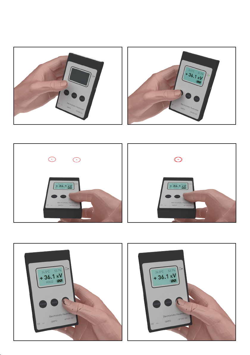
Press the HOLD key button briey in order to lock the
displayed value.
6
4.4. OPERATION METHOD
When starting up, press the power button for 3 seconds
and the back of the display screen will enlighten. Press
the button for another 3 seconds and the background will
turn off.
1- Press the power button to turn on the measurer, the
status indicator light is on, the green light indicator is on,
the sound alarm rang once and the content is displayed
on the screen.
Press the HOLD key button briey so the displayed value
returns to zero.
Place the measurer at a distance of two infrared lamps from the object to be measured and then, focus on it (the red
LEDs must be overlapping each other – approx. 5cm from the surface to measure) and read the measured value on the
display screen.
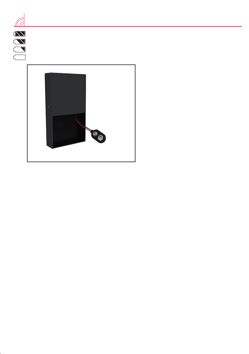
5. BATTERY REPLACEMENT
Sufcient battery
Quite sufcient battery
Weak battery
Empty battery
When the battery power is insufcient, the static
eld meter cannot start normally. When it is
operating but the battery is low, the screen will
ash and then turn off automatically. At that
point, the battery needs to be replaced before
the measurer can work properly again.
Battery replacement: remove the battery cover
at the back of the static eld meter, remove
the old battery from the buckle, fasten the new
battery, put it back into place and replace the
cover.
Note: Please turn off the power when not in
use. Do not replace the battery when the static
eld meter is working to avoid any damage to
the device.
7

7. MAINTENANCE
1. In order to ensure the good performance of the product, please store it in a dark and dry place when not in use, do not
press it heavily.
2. The device is a precision detector, do not use strong vibration.
3. Do not immerse electronic equipment.
www.novacom-vacuum.com
6. COMMUNICATION PROTOCOL
Baud rate: 10K
Frame format: standard pin
Frame type: data frame
ID(Address)= 1, 2, 3,… (settable)
Default Ack= 1 Interid= 0
Frame id= (CanIdData->Address<<4) | (CanIdData->Ack<<3) | (CanIdData->Interid &0x07);
For example:
ID (Address) = 1 frame id = 00 00 00 18
ID (address) = 2 frames id = 00 00 00 28
[8-bit data description (hexadecimal)]
10(default) 00 (working state) 00 (working type) 01 (working distance) X0 00 00 00 (measured data)
Working state description: 00 normal 02 max min alarm
Working type description: 00 default
Description of working distance: 01 - > 25mm 02 - > 50mm
Description of measurement data: X0 00 00 00 (X=0 negative static X=1 positive static)
[parameter setting]
Modication ID: 10 A0 01 (id= 01 02 03……….) 00 00 00 00 00
Modify test distance: 10 A1 01 (01 02) 00 00 00 00 00
Modify the positive and negative alarm values: 10 A3 27 10
(positive static telegraph alarm value 10000v) 27 10 (negative static alarm value 10000v) 00 00
[electrostatic voltage reading]
Read electrostatic voltage value: 10 B4 00 00 00 00 00 00
6.1. DESCRIPTION OF THE CAN PROTOCOL
Table of contents
Popular Measuring Instrument manuals by other brands


Task Force Tips
Task Force Tips MONSOON MONITOR Instructions for installation, safe operation and maintenance

Dover
Dover OPW SiteSentinel iSite installation manual

PQ Plus
PQ Plus UMD 97EVU Quick start manual

Segen Solar
Segen Solar Solis DTSD1352 Application note

Kleinwaechter
Kleinwaechter EFM 023 BGT manual

PeakTech
PeakTech 1645 Operation manual


