Novanta NDS ScaleOR User manual

ScaleOR™
Video Scaling System
USER MANUAL
ENGLISH


© 2018 NDS Surgical Imaging, LLC. All rights reserved.
Information in this document has been carefully checked for accuracy; however, no guarantee is given to
the correctness of the contents. This document is subject to change without notice. NDS provides this
information as reference only. Reference to products from other vendors does not imply any
recommendation or endorsement.
This document contains proprietary information protected by copyright. No part of this manual may be
reproduced by any mechanical, electronic, or other means, in any form, without prior written permission of
NDS.
All trademarks are the property of their respective owners.


i
Table of Contents
Tab 1
Warnings and Cautions --------------------------------- -------------------- ii
Recycling ------------------------------------------------------------------------- ii
Declaration of Conformity --------------------------------------------------- iii
Legal Statement ------------------------------------------- -------------------- iii
Tab 2
About This Manual ------------------------------------------------------------- 1
Intended Use and Contraindications ------------------------------------- 1
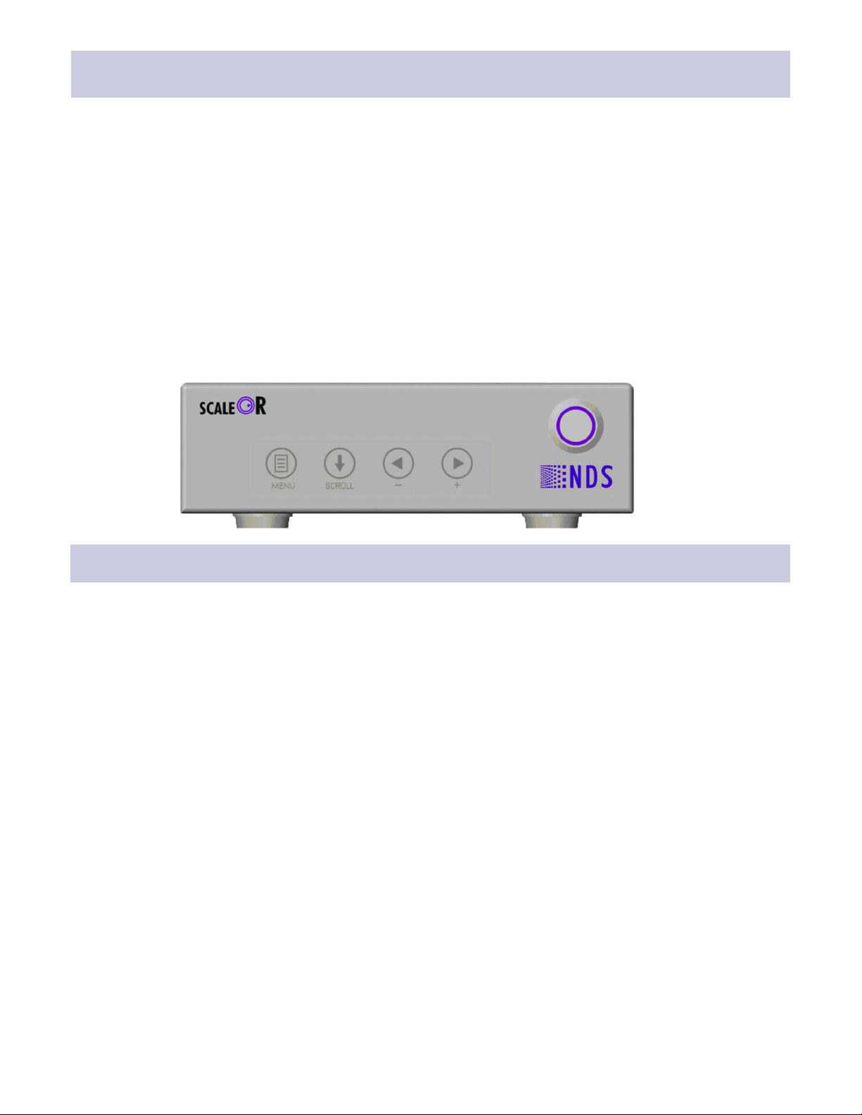
ScaleOR Overview ------------------------------------------------------------- 2
General Information ----------------------------------------------------------- 2
Tab 3
Connector Panel ---------------------------------------------------------------- 3
Output Mode Switches ------------------------------------------------------- 5
Electrical Symbols -------------------------------------------------------------- 5
DVI and SDI Output Mode Switch Settings ----------------------------- 6
DVI and HDBaseT Output Mode Switch Settings --------------------- 7
Power Supply and Wall Adapters ------------------------------------------ 8
Removable Input Modules -------------------------------------------------- 9
Module Removal and Installation ----------------------------------------- 9
Tab 4
DVI and SDI System Conguration Example ------------------------- 10
DVI and HDBaseT System Conguration Example ----------------- 11
Tab 5
Startup -------------------------------------------------------------------------- 12
Tab 6
Control -------------------------------------------------------------------------- 13
Menu Overview -------------------------------------------------------------- 13
ScaleOR Setup ---------------------------------------------------------------- 14
Picture Menu --------------------------------------------------------------- 14
Color Menu------------------------------------------------------------------ 15
Setup Menu ----------------------------------------------------------------- 16
Modes Menu ---------------------------------------------------------------- 17
Output Modes Table ----------------------------------------------------- 18
Restoring Factory Defaults --------------------------------------------- 18
Tab 7
Serial Port Setup and Test ------------------------------------------------- 19
Tab 8
Troubleshooting and Test Section -------------------------------------- 20
Tab 9
Drawing and Dimensions -------------------------------------------------- 21
Tab 10
Connectors and Pin Outs -------------------------------------------------- 22
Cable Bend Radius ----------------------------------------------------------- 23
Tab 11
Specications ----------------------------------------------------------------- 24
Video Formats ----------------------------------------------------------------- 25
Video Inputs ------------------------------------------------------------------- 26
Cleaning and Disinfecting Instructions -------------------------------- 27
Electromagnetic Compatibility (EMC) Tables ------------------------ 28

1
ii
Warnings and Cautions
WARNING:
CLASS I LASER PRODUCT. DO NOT STARE INTO LASER BEAM
Safety Compliance:
This product meets the requirements of EN-60601-1 so as to conform to the Medical Device Direcve
93/42/EEC and 2007/47/EC (general safety informaon).
Safety Compliance:
This product is T.U.V. approved WITH RESPECT TO ELECTRIC SHOCK, FIRE AND MECHANICAL HAZARDS ONLY
IN ACCORDANCE WITH CAN/CSA C22.2 NO. 60601-1 and ANSI/AAMI ES60601-1.
This symbol alerts the user that important informaon regarding the installaon and / or operaon of this
equipment follows. Informaon preceded by this symbol should be read carefully in order to avoid damaging the
equipment.
This symbol warns user that un-insulated voltage within the unit may have sufficient magnitude to cause electrical
shock. Therefore, it is dangerous to make contact with any part inside the unit. To reduce the risk of electric
shock, DO NOT remove cover (or back). There are no user serviceable parts inside. Refer servicing to qualified
service personnel.
This symbol cauons the user that important informaon regarding the operaon and / or maintenance of this
equipment has been included. Informaon preceded by this symbol should be read carefully to avoid damage to
the equipment.
This symbol denotes the manufacturer.
This symbol denotes the manufacturer’s European Community representave.
To prevent fire or shock hazards, do not expose this unit to rain or moisture. Also, do not use the polarized plug on this unit
with an extension cord receptacle or other outlets, unless the prongs can be fully inserted. The product is designed to meet
the medical safety requirements for a paent vicinity device.
This product is a Class I medical device. No modificaons are allowed.
This equipment/system is intended for use by healthcare professionals only.
This product is energized from an external electrical power source for class 1 equipment. It is the responsibility
of the installer to test the earth ground on the unit to verify that it complies with the hospital, local and naonal
impedance requirements.
This product complies to the above standards only when used with the supplied medical grade power supply.
Power supply: Ault and SL Power Electronic Corp Model: MENB1030A1200C02 12VDC
Oponal power supply: GTM91120-3024-T3A, 24VDC
Disconnect the power supply from the AC mains. The power supply is the only recognized disconnect device.
The MEDICAL EQUIPMENT should be posioned so that its disconnect device is readily accessible.
The product should be powered from a center tapped circuit when used in the US at voltages over 120 volts. Product is
intended for connuous operaon.
Recycling:
Follow local governing ordinances and recycling plans regarding the recycling or disposal of this
equipment .

iii
Declarations of Conformity
Legal Statement
NDS sells its products through other medical device manufacturers, distributors and resellers and therefore, purchasers of this NDS
product should consult with the entity through which this product was originally purchased regarding the terms of any applicable
product warranties provided by such entity, if any.
NDS neither assumes nor authorizes any person to assume for it any other liabilities in conjunction with and/or related to the sale
and/or use of its products. To ensure proper use, handling and care of NDS products, customers should consult the product specic
literature, instruction manual, and/or labeling included with the product or otherwise available.
Customers are cautioned that system conguration, software, the application, customer data and operator control of the system,
among other factors, affect the product’s performance. While NDS products are considered to be compatible with many systems,
specic functional implementation by customers may vary. Therefore, suitability of a product for a specic purpose or application
must be determined by the consumer and is not warranted by NDS.
NDS SPECIFICALLY DISCLAIMS ALL WARRANTIES OF ANY KIND, WHETHER EXPRESS, IMPLIED AND/OR STATUTORY, INCLUDING, BUT
NOT LIMITED TO WARRANTIES OF MERCHANTABILITY, FITNESS AND/OR OF SUITABILITY FOR A PARTICULAR PURPOSE, AND NON-
INFRINGEMENT WITH RESPECT TO ALL NDS PRODUCTS OR SERVICES. ANY AND ALL OTHER WARRANTIES, REPRESENTATIONS AND/
OR GUARANTEES, OF ANY TYPE, NATURE OR EXTENT, BE IT IMPLIED, EXPRESS AND/OR WHETHER ARISING UNDER OR AS A RESULT
OF ANY STATUTE, LAW, COMMERCIAL USAGE, CUSTOM, TRADE OR OTHERWISE, ARE HEREBY EXPRESSLY EXCLUDED AND
DISCLAIMED.
NDS, its suppliers and/or distributors are not liable, directly or by way of indemnity for any special, incidental, consequential,
punitive, exemplary or indirect damages, including but not limited to alleged damages for delayed shipment, non-delivery, product
failure, product design or production, inability to use such products or services, loss of future business (lost prots), or from any
other cause, whatsoever, in connection with or arising from the purchase, sale, lease, rental, installation or use of such NDS
products, these terms and conditions, or with respect to any the terms of any agreement which incorporates these terms and
conditions.
SOME JURISDICTIONS DO NOT ALLOW EXCLUSIONS AND DISCLAIMERS OF CERTAIN WARRANTIES OR LIMITATIONS OF LIABILITY, SO
THE LIMITATIONS AND/OR EXCLUSIONS, SET FORTH HEREIN, MAY NOT APPLY. IN THAT EVENT LIABILITY WILL BE LIMITED TO THE
GREATEST EXTENT PERMITTED BY LAW IN THE SUBJECT JURISDICTION.
The information provided in this document, including all designs and related materials, is the valuable property of NDS and / or its
licensors and, as appropriate, they reserve all patent, copyright, and other proprietary rights to this document, including all design,
manufacturing reproduction, use, and sales rights thereto, except to the extent said rights are expressly granted to others.
FCC and Council Directives of European Standards:
This device complies with Part 15 of FCC rules and 93/42/EEC of the Council Directives of European Standards Directive as
amended by 2007/47/EC. Operation is subject to the following two conditions: (1) This device may not cause harmful interference,
and (2) this device must accept any interference received, including interference that may cause undesirable results.
1. Use the specied cables with this device so as not to interfere with radio and television reception. Use of other cables and /
or adapters may cause interference with other electronic equipment.
2. This equipment has been tested and found to comply with the limits pursuant to FCC part 15 and CISPR 11. This equipment
generates, uses and can radiate radio frequency energy and, if not installed and used in accordance with the instructions, may
cause harmful interference to radio communications.
IEC:
This equipment has been tested and found to comply with the limits for medical devices to the IEC 60601-1-2. These limits are
designed to provide reasonable protection against harmful interference in a typical medical installation. This equipment
generates, uses and can radiate radio frequency energy and, if not installed and used in accordance with the instructions, may
cause harmful interference to other devices in the vicinity.
FCC, Council Directives of European Standards and IEC:
There is no guarantee that interference will not occur in a particular installation. If this equipment does cause harmful interference
to radio or television reception, which can be determined by turning the equipment off and on, the user is encouraged to try to
correct the interference by one or more of the following measures:
Reorient or relocate the receiving antenna.
Increase the separation between the equipment and receiver.
Connect the equipment into an outlet on a circuit different from that to which the receiver is connected.
Consult your dealer or an experienced radio/TV technician for help.
Accessory equipment connected to this product must be certied according to the respective IEC Standards (i.e., IEC 60950-1) for
data processing equipment and IEC 60601-1 for medical equipment). Furthermore, all congurations shall comply with the system
standard, IEC 60601-1-1. Anyone who connects additional equipment to the signal input part or signal output part congures a
medical system, and is therefore responsible that the system complies with the requirements of system standard IEC 60601-1-1.
Whoever is responsible for securing the unit to a system needs to insure that the mounting equipment used with this product
complies to IEC standard 60601-1. If in doubt, consult the technical services department or your local representative.

iv

2
1
This manual is designed to assist the user with installaon, setup and operaon of the ScaleOR and its associated
displays. A list of displays that may be used with the ScaleOR is in the Compable Displays secon under General
Informaon on the following page.
A numbered tab on the side of the page denotes the beginning of a secon.
About This Manual
Intended Use:
This device is intended for use in a medical environment to deliver high quality video and graphic images.
Contraindications:
This device may not be used in the presence of flammable anesthecs mixture with air, oxygen or nitrous oxide.
Also, it is not intended for life support applicaons.
No part of this product may come in contact with a paent. Never touch the product and a paent at the same
me.
Warning:
Because invisible laser radiaon may be emied from the aperture of the port when no fiber cable is connected,
avoid exposure to laser radiaon and do not stare into open apertures.
For mission crical applicaons, we strongly recommend that a replacement unit be immediately available.
Intended Use and Contraindications
Installaon:
ScaleOR units may be stacked on a equipment carrier, a surgical cart or mounted in a standard 19” rack.
Ensure that the air vents are not blocked.
Power Supply:
ScaleOR with DVI and SDI connectors — The provided power supply, Ault and SL Power Electronic Corp Model:
MENB1030A1200C02 12VDC, includes 4 interchangeable wall plug adapters. An alternate power supply
GTM91120-3024-T3A, 24VDC. Drawings of the power supply, its adapters, and adapter installaon informaon
are on page 8.
ScaleOR with DVI and HDBaseT (HDBT) connectors — The HDBaseT connector is Power over Ethernet (PoE)
compable and can be used to power the ScaleOR. An oponal power supply is available.
Compable Displays:
1. HD displays with a DVI input.
2. HD displays with HD-SDI or 3G-SDI input.
3. HD displays with HDBaseT input.
4. HD displays with Fiber Opc input. Note: The ScaleOR Fiber Opc output is an oponal feature.
Control Opons:
The ScaleOR may be controlled from:
1. The keypad on the front of the ScaleOR. Using the keypad requires that the ScaleOR be connected to a
display.
2. A PC via the ND-OS port. See Serial Port Setup and Test on page 16.
The NDS Unified Serial Commands (P/N 60A0156) document contains a complete set of serial commands for the
ScaleOR. Please contact your NDS sales representave for details.
General Information
The ScaleOR accepts 1 of following 4 input modules:
DVI-D
SDI
VGA
S-Video / Composite
The ScaleOR is has two opons of fixed output connectors:
DVI and SDI
DVI and HDBaseT (HDBT)
The drawings on pages 3 and 4 show the locaons of the two versions of fixed output connectors and the input
module.
The output mode (resoluon) may be selected using the DIP switches located on the boom of the ScaleOR (see
Output Mode Switch Sengs table on page 5).
ScaleOR Overview
2

3
3
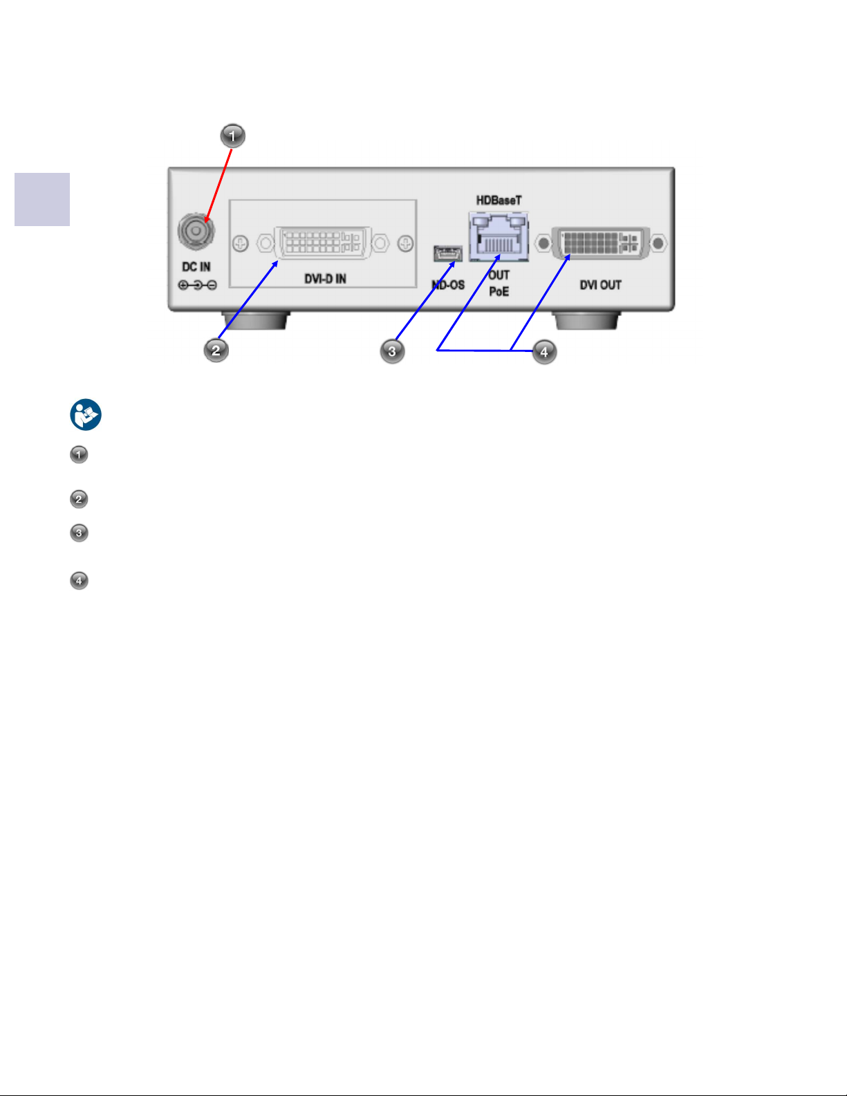
Connector Panel
Notes:
Power input. Use the provided 12VDC power supply only.
Oponal Fiber Opc output
Input module, DVI-D module shown, all input modules are shown on page 9.
The ND-OS connector allows the ScaleOR to be controlled remotely via serial commands. It is also used to
install BIOS upgrades.
SDI and DVI video outputs.
The ScaleOR with fixed DVI and SDI output connectors is shown below.
4
3
Notes:
Power input for use with the oponal 12VDC power supply only. The HDBaseT (PoE) port is the
recommended power source for the ScaleOR HDBaseT.
Input module, DVI-D module shown, all input modules are shown on page 9.
The ND-OS connector allows the ScaleOR to be controlled remotely via serial commands. It is also used to
install BIOS upgrades.
HDBaseT and DVI video outputs. The HDBaseT port is Power over Ethernet (PoE) compable and should be
used to power the ScaleOR HDBaseT.
NOTE: The PoE port supplies the ScaleOR HDBT power, as the default power source. The ScaleOR HDBT
can be powered using the wall adapter, as an oponal power source.
The ScaleOR with fixed DVI and HDBaseT output connectors is shown below.
5
3
Electrical Symbols
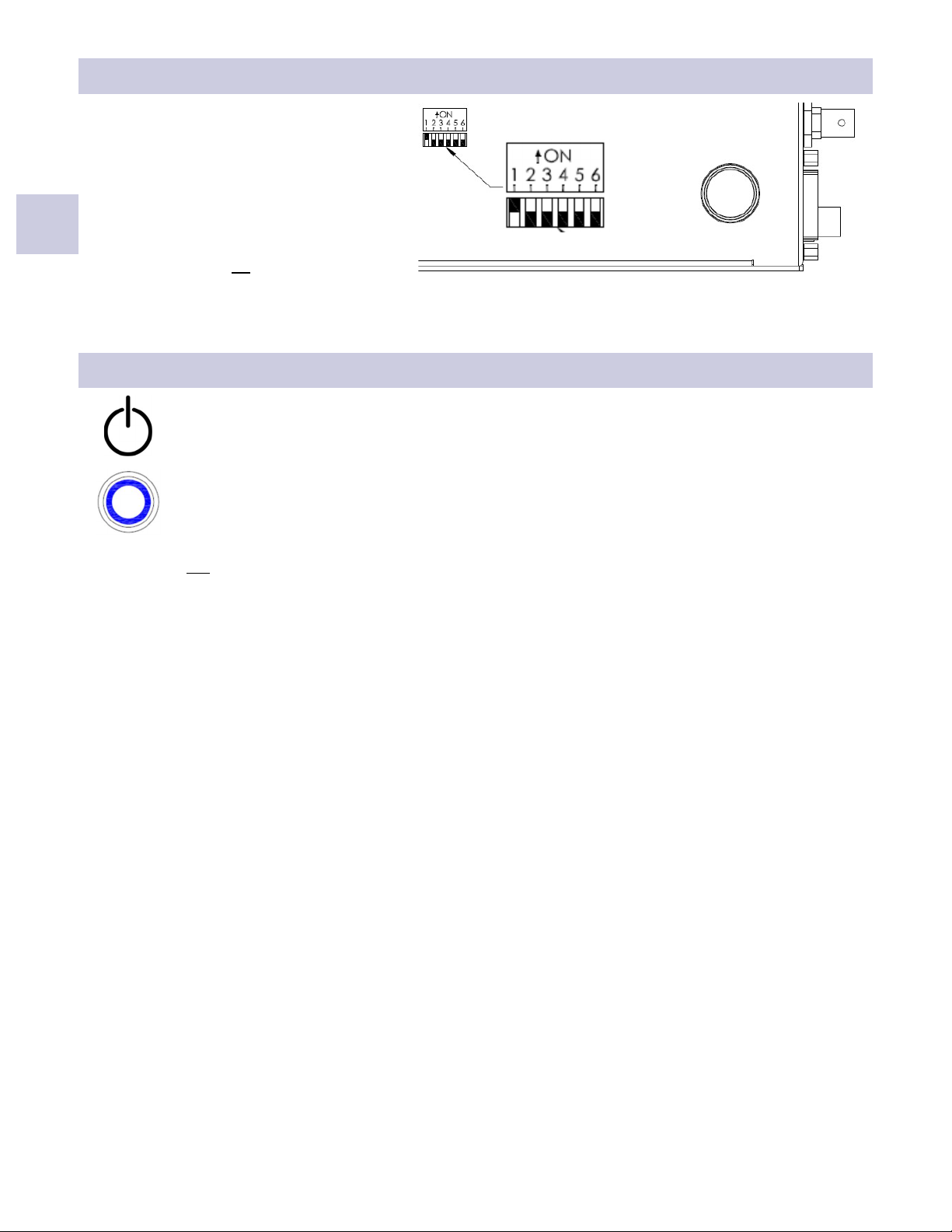
Output Mode Switches
The Output Mode Switches, accessible on the
underside of the unit, allow the user to select
1 of 46 output modes. The Output Mode
Switch Sengs table on the following page
shows the switch sengs required to select a
given output mode. Seng the output mode
from the On Screen Menu (OSM) requires that
all switches be set to off.
Power Switch:
The Power Switch symbol is shown to the le.
The power switch is push on / push off and is shown below the Power Switch symbol. When the
switch is off, the ring around the center poron is white. When the switch is on, the center
poron is depressed and the ring is illuminated blue. The illustraon shows the switch in the
ON state. When the ScaleOR is turned on the blue ring flashes at the rate of 5 flashes per
second for 15 seconds then, becomes steady when a video signal is detected. If a video signal is
not detected the ring connues flashing at the rate of 1 flash per second.

DVI and SDI Output Mode Switch Settings
6
Legend: F = Off, O = On
Mode DIP Switch
Index DVI Mode SDI Mode 6 5 4 3 2 1
0 720x487/59.94P 720x480/59.94I O O O O O O
1 720x576/50.00P 720x576/50.00I O O O O O F
2 1280X720/23.98P 1280X720/23.98P O O O O F O
3 1280X720/24.00P 1280X720/24.00P O O O O F F
4 1280X720/25.00P 1280X720/25.00P O O O F O O
5 1280X720/29.97P 1280X720/29.97P O O O F O F
6 1280X720/30.00P 1280X720/30.00P O O O F F O
7 1280x720/50.00P 1280x720/50.00P O O O F F F
8 1280x720/59.94P 1280x720/59.94P O O F O O O
9 1280x720/60.00P 1280x720/60.00P O O F O O F
10 1920x1080/50.00P 1920x1080/50.00I O O F O F O
11 1920x1080/59.94P 1920x1080/59.94I O O F O F F
12 1920x1080/60.00P 1920x1080/60.00I O O F F O O
13 1920x1080/23.98P 1920x1080/23.98P O O F F O F
14 1920x1080/24.00P 1920x1080/24.00P O O F F F O
15 1920x1080/25.00P 1920x1080/25.00P O O F F F F
16 1920x1080/29.97P 1920x1080/29.97P O F O O O O
17 1920x1080/30.00P 1920x1080/30.00P O F O O O F
18 1920x1080/50.00P 1920x1080/50.00P O F O O F O
19 1920x1080/59.94P 1920x1080/59.94P O F O O F F
20 1920x1080/60.00P 1920x1080/60.00P O F O F O O
21 640x480/60 VGA N/A O F O F O F
22 640x480/75 VGA N/A O F O F F O
23 640x480/85.01 VGA N/A O F O F F F
24 800x600/60.32 SVGA N/A O F F O O O
25 800x600/75 SVGA N/A O F F O O F
26 800x600/85.06 SVGA N/A O F F O F O
27 1024x768/60 XGA N/A O F F O F F
28 1024x768/75.03 XGA N/A O F F F O O
29 1024x768/85 XGA N/A O F F F O F
30 1152x864/70.01 XGA N/A O F F F F O
31 1152x864/75 XGA N/A O F F F F F
32 1152x864/85 XGA N/A F O O O O O
33 1280x768/59.87 WXGA N/A F O O O O F
34 1280x960/60 SXGA N/A F O O O F O
35 1280x960/75 SXGA N/A F O O O F F
36 1280x960/85 SXGA N/A F O O F O O
37 1280x1024/60.02 SXGA N/A F O O F O F
38 1280x1024/75.02 SXGA N/A F O O F F O
39 1280x1024/85.02 SXGA N/A F O O F F F
40 1360X768/60.01WXGA N/A F O F O O O
41 1366X768/59.79 WXGA N/A F O F O O F
42 1440X900/59.89 WXGA N/A F O F O F O
43 1600X1200/60 UXGA N/A F O F O F F
44 1680X1050/59.95 WSXGA N/A F O F F O O
45 1920x1200/50 WUXGA N/A F O F F O F
46 1920x1200/60 WUXGA N/A F O F F F O
47 Use Menu * F F F F F F
* Note: To set the output mode from the ScaleOR OSM, all switches must be set to Off .

DVI and HDBaseT Output Mode Switch Settings
7
Legend: F = Off, O = On
Mode DIP Switch
Index DVI Mode HDBT Mode 6 5 4 3 2 1
0 720x487/59.94P 720x487/59.94P O O O O O O
1 720x576/50.00P 720x576/50.00P O O O O O F
2 1280X720/23.98P 1280X720/23.98P O O O O F O
3 1280X720/24.00P 1280X720/24.00P O O O O F F
4 1280X720/25.00P 1280X720/25.00P O O O F O O
5 1280X720/29.97P 1280X720/29.97P O O O F O F
6 1280X720/30.00P 1280X720/30.00P O O O F F O
7 1280x720/50.00P 1280x720/50.00P O O O F F F
8 1280x720/59.94P 1280x720/59.94P O O F O O O
9 1280x720/60.00P 1280x720/60.00P O O F O O F
10 1920x1080/50.00P 1920x1080/50.00P O O F O F O
11 1920x1080/59.94P 1920x1080/59.94IP O O F O F F
12 1920x1080/60.00P 1920x1080/60.00P O O F F O O
13 1920x1080/23.98P 1920x1080/23.98P O O F F O F
14 1920x1080/24.00P 1920x1080/24.00P O O F F F O
15 1920x1080/25.00P 1920x1080/25.00P O O F F F F
16 1920x1080/29.97P 1920x1080/29.97P O F O O O O
17 1920x1080/30.00P 1920x1080/30.00P O F O O O F
18 1920x1080/50.00P 1920x1080/50.00P O F O O F O
19 1920x1080/59.94P 1920x1080/59.94P O F O O F F
20 1920x1080/60.00P 1920x1080/60.00P O F O F O O
21 640x480/60 VGA N/A O F O F O F
22 640x480/75 VGA N/A O F O F F O
23 640x480/85 VGA N/A O F O F F F
24 800x600/60 SVGA N/A O F F O O O
25 800x600/75 SVGA N/A O F F O O F
26 800x600/85 SVGA N/A O F F O F O
27 1024x768/60 XGA N/A O F F O F F
28 1024x768/75 XGA N/A O F F F O O
29 1024x768/85 XGA N/A O F F F O F
30 1152x864/70 XGA N/A O F F F F O
31 1152x864/75 XGA N/A O F F F F F
32 1152x864/85 XGA N/A F O O O O O
33 1280x768/60 WXGA N/A F O O O O F
34 1280x960/60 SXGA N/A F O O O F O
35 1280x960/75 SXGA N/A F O O O F F
36 1280x960/85 SXGA N/A F O O F O O
37 1280x1024/60 SXGA N/A F O O F O F
38 1280x1024/75 SXGA N/A F O O F F O
39 1280x1024/85 SXGA N/A F O O F F F
40 1360X768/60 WXGA N/A F O F O O O
41 1366X768/60 WXGA N/A F O F O O F
42 1440X900/60 WXGA N/A F O F O F O
43 1600X1200/60 UXGA N/A F O F O F F
44 1680X1050/60 WSXGA N/A F O F F O O
45 1920x1200/50 WUXGA N/A F O F F O F
46 1920x1200/60 WUXGA N/A F O F F F O
47 Use Menu N/A F F F F F F
* Note: To set the output mode from the ScaleOR OSM, all switches must be set to Off .
8
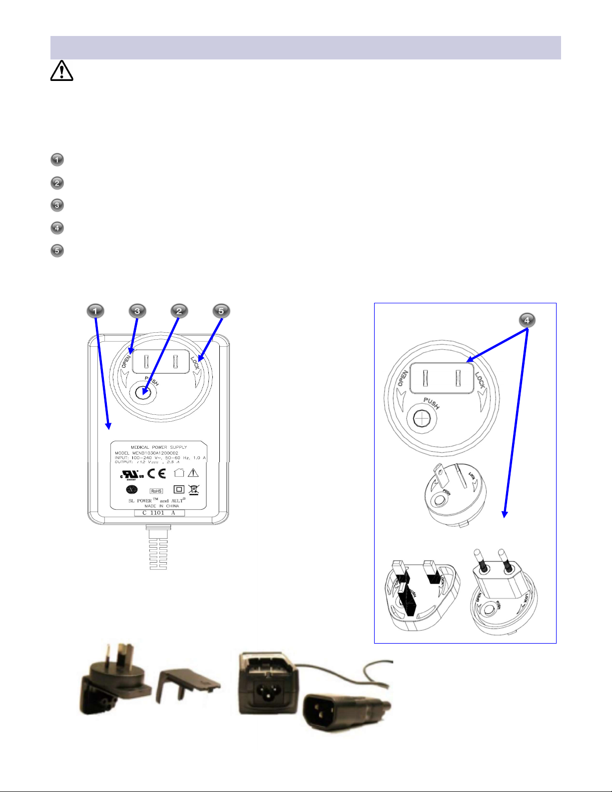
Power Supply and Wall Adapters
The power supply is shown with the US wall adapter installed. To exchange the adapter, proceed as
follows:
The ScaleOR with fixed DVI and SDI output connectors uses the power supply as the power source.
The ScaleOR with fixed DVI and HDBaseT output connectors uses Power over Ethernet (PoE) through the
HDBaseT port as the default power source. An oponal power supply is available.
Place the power supply on your work surface as shown.
Press and hold the buon labeled PUSH.
Twist the adapter 1/8 turn toward the OPEN arrow, and li it off the power supply.
Select one of the provided wall adapters.
Align the tabs on the boom of the adapter with the notches on the power supply and place the adapter on
the power supply. Press the adapter down and twist it toward the LOCK arrow unl it clicks into place.
GTM91120-3024-T3A, 24Vdc

VGA S-Video / Composite
DVI-D
3G-SDI
Removable Input Modules
Input Modules:
Four types of input modules are available: DVI-D, 3G-SDI, VGA and S-Video / Composite
The DVI-D input module accepts DVI signals up to 1920 x 1200 progressive at 60Hz.
The 3G-SDI input module accepts SDI signals up to 1920 x 1080 progressive at 60Hz.
The VGA input module accepts analog signals up to 1920 x 1200 progressive at 60Hz.
The S-Video / Composite input module accepts S-Video / Composite NTSC or PAL signals .
Module Removal and Installation
The ScaleOR must be turned off prior to installing or replacing the input module.
Input Module Removal:
Use a number 1 Phillips screwdriver to loosen, but not remove, the screws located on the le and right sides of
the module mounng plate. When the screws are clear of the chassis, remove the module by gripping the
screws and pulling the module out.
Installation:
Slide the new module into the chassis unl it contacts the connector, then push gently unl the module seats.
The module is correctly seated when the mounng plate is flush with the back panel. Thread the screws into the
chassis unl they touch the mounng plate, then ghten each screw by turning it another quarter turn.
9
VGA Module Switches
Function Switch 1 Switch 2 Switch 3
RGBS On On Off
YPbPr Off On Off
VGA On Off Off
SOG Off Off Off
OSM / RS-232 Off Off On
1. To select the Input Format using the OSM or via Serial
control switch 3 must be On. When switch 3 is On
switches 1 and 2 are disabled.
2. To select the input format manually turn switch 3 Off.
Then, using the table to the le, set switches 1 and 2
to the format of the input signal.
Any one of the input modules shown below may be installed in the card slot.

4
DVI and SDI System Configuration Example
10
DVI Out
SDI, DVI, VGA, or S-Video / Composite Source
Optional PC
control
▲
▲
◄ ►
SDI Out
▲
A system configuraon with the ScaleOR with fixed DVI and SDI output connectors is shown below.

4
DVI and HDBaseT System Configuration Example
11
DVI Out
SDI, DVI, VGA, or S-Video / Composite Source
Optional PC
control
▲
▲
◄ ►
▲
HDBaseT Out
A system configuraon with the ScaleOR with fixed DVI and HDBaseT output connectors is shown below.

5
Startup
Connect one of the ScaleOR outputs to a compable monitor. Connect a video source to the ScaleOR input.
Press the power buon located on the front panel of the ScaleOR. The illuminated blue ring on the power
buon flashes for 15 seconds then, when a video signal is detected, becomes steady. If a video signal is not
detected the ring connues flashing.
The NDS logo is displayed on the monitor unl the ScaleOR inializaon is complete. At which me the
illuminated ring stops flashing, if a video signal is detected, and becomes steady blue. At this me an image
of the video signal connected to the ScaleOR input is displayed on the monitor.
If the ScaleOR has been turned on for more than 15 seconds and a video signal is not detected the blue ring
is will flash at the rate of 1 flash per second.
ScaleOR
12
Table of contents
Other Novanta Media Converter manuals

Popular Media Converter manuals by other brands

TeAx Technology
TeAx Technology ThermalCapture Grabber USB Series Mounting instructions

EtherWAN
EtherWAN EMC1200R installation guide

Digital audio
Digital audio adda 2402 user manual

I-novative
I-novative Factory-Link-SPE-G user manual

AJA
AJA ADA4 Mini-Converter Installation & operation guide

Relectronic
Relectronic C-58 Series user manual

Littfinski Daten Technik
Littfinski Daten Technik S-DEC-4-MM-B Assembly instruction

Baumer
Baumer Hubner FOG 9 + GT 7 Installation and operating instructions

Net Optics
Net Optics 10 GigaBit Media Converter Tap installation guide

Slinex
Slinex XR-40IPHD user manual

Atlona
Atlona AT-AVS100 user manual

Danfoss
Danfoss iC7 Series installation guide


