Novanta MOVIA User manual

ENGINEERED BY
CAMBRIDGE TECHNOLOGY
MOVIA, 2-Axis Scan Head
User Manual
Read carefully before using.
Retain for future reference.

MOVIA, 2-Axis Scan Head – User Manual, 1040–0004 Rev. 03 ii
TABLE OF CONTENTS
1Important Information 1
1.1 Safety Symbols ......................................................................................................................1
1.2 Safety Labels..........................................................................................................................2
1.3 Customer Support ...............................................................................................................3
2Product Overview 5
2.1 Principles of Operation ......................................................................................................5
2.2 Product Use ............................................................................................................................6
2.3 Product Configuration .......................................................................................................6
3Installation 8
3.1 Required System Parts ......................................................................................................8
3.2 Recommended Accessories (Customer Supplied)................................................9
Laser Shutter..........................................................................................................................9
3.3 Installation Instructions....................................................................................................10
3.3.1 Unpack the MOVIA Scan Head.....................................................................10
3.3.2 Mount the Scan Head.......................................................................................10
3.3.3 Attach the Power/Data Cable to the Scan Head .................................. 11
3.3.4 Electrical – Power Supply Requirements................................................. 14
3.3.5 Apply Power to the Scan Head.................................................................... 14
3.3.6 Install the F-Theta Lens and Required Lens Spacer ........................... 16
3.3.7 Perform Scan Head Calibration.................................................................... 16
3.4 Set up for Initial Use.......................................................................................................... 18
4Troubleshooting and Maintenance 19
4.1 Troubleshooting.................................................................................................................. 19
4.2 Optic Care ............................................................................................................................. 21
5Warranty Statement 22

MOVIA, 2-Axis Scan Head – User Manual, 1040–0004 Rev. 03 iii
LIST OF FIGURES
Figure 1: System Diagram....................................................................................................................5
Figure 2: Beam Direction .....................................................................................................................6
Figure 3: Product Label........................................................................................................................7
Figure 4: Location of Optical Beam Hazard Zones and Recommended Shutter
Location ......................................................................................................................................................9
Figure 5: Location of Metric Dowel Pin Holes ........................................................................... 11
LIST OF TABLES
Table 1: Cable Channel Usage........................................................................................................... 11
Table 2: Pin Assignments................................................................................................................... 12
Table 3: Recommended Delay Settings for Initial Use.......................................................... 18
Table 4: Scan Head Symptoms, Causes, and Recommended Actions .......................... 19
MOVIA, 2-Axis Scan Head – User Manual, 1040–0004 Rev. 03 1
1IMPORTANT INFORMATION
IMPORTANT
For your protection, carefully read these instructions before installing and
operating the scan head.
Retain these instructions for future reference.
Cambridge Technology reserves the right to update this user manual at any
time without prior notification.
If product ownership changes, this manual should accompany the product.
1.1 SAFETY SYMBOLS
DANGER
Indicates a hazardous situation which, if not avoided, will result in serious injury
or death.
Its use should be limited to the most extreme situations.
WARNING
Indicates a hazardous situation which, if not avoided, could result in serious
injury or death.
1 Important Information 1.2 Safety Labels
MOVIA, 2-Axis Scan Head – User Manual, 1040–0004 Rev. 03 2
CAUTION
Indicates a hazardous situation which, if not avoided, could result in minor or
moderate injury.
IMPORTANT
Indicates information considered important but not directly hazard related (e.g.
security, hygiene, or equipment or property damage).
1.2 SAFETY LABELS
DANGER
Laser radiation
can cause severe retinal and corneal burns, burns on the skin, and may pose a
fire risk.
•To avoid injury and reduce risk of fire, please follow the control measures
and safety guidelines provided by the laser’s manufacturer, and those
established by your Laser Safety Officer (LSO), Radiation Safety Officer
(RSO), or safety department of your business or institution.
ESD WARNING
Electrostatic discharge and improper handling
can damage MOVIA scan head’s electronics.
•Keep the equipment sealed until it is located at a proper static control
station.
A proper static control station should include:
•A soft grounded conductive tabletop or grounded conductive mat on the
tabletop.

1 Important Information 1.3 Customer Support
MOVIA, 2-Axis Scan Head – User Manual, 1040–0004 Rev. 03 3
•A grounded wrist strap with the appropriate (1 MΩ) series resistor
connected to the tabletop mat and ground.
•An adequate earth ground connection, such as a water pipe or AC ground.
•Conductive bags, trays, totes, racks, or other storage.
•Properly grounded power tools.
•Personnel handling ESD items should wear ESD protective garments and
ground straps.
IMPORTANT
Electrostatic discharge and improper handling
can damage MOVIA scan head’s electronics.
•Ship equipment returned to the factory in anti-static packaging.
IMPORTANT
Customers assume all responsibility for maintaining a laser-safe working
environment.
Original equipment manufacturer (OEM) customers assume all responsibility for
CDRH (Center for Devices and Radiological Health) certification.
1.3 CUSTOMER SUPPORT
Before contacting Novanta Photonics for assistance, review appropriate sections
in the manual that may answer your questions.
After consulting this manual, please contact one of our worldwide offices between
9 AM and 5 PM local time.
Americas, Asia Pacific
Novanta Headquarters, Bedford, USA
Phone: +1-781-266-5700
Email: photon[email protected]om

1 Important Information 1.3 Customer Support
MOVIA, 2-Axis Scan Head – User Manual, 1040–0004 Rev. 03 4
Europe, Middle East, Africa
Novanta Europe GmbH, Wackersdorf, Germany
Phone: +49 9431 7984-0
Email: photon[email protected]om
Milan, Italy
Phone: +39-039-793-710
Email: photon[email protected]om
China
Novanta Sales & Service Office, Shenzhen, China
Phone: +86-755-8280-5395
Email: photonics.china@novanta.com
Novanta Sales & Service Office, Suzhou, China
Phone: +86-512-6283-7080
Email: photonics.china@novanta.com
Japan
Novanta Service & Sales Office, Tokyo, Japan
Phone: +81-3-5753-2460
Email: photonics.japan@novanta.com
MOVIA, 2-Axis Scan Head – User Manual, 1040–0004 Rev. 03 5
2PRODUCT OVERVIEW
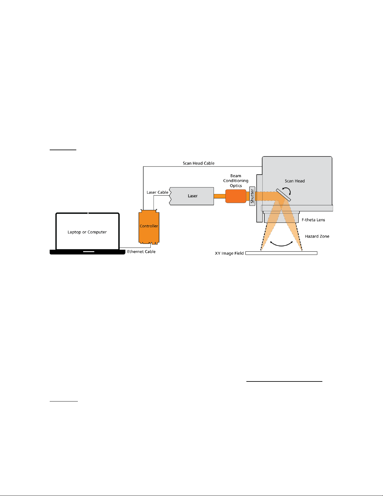
MOVIA scan heads are used as part of a galvanometer-based laser system and
steer optical beams on a XY image field (2D) for all possible laser applications. See
Figure 1
Figure 1: System Diagram
2.1 PRINCIPLES OF OPERATION
In a MOVIA scan head, two galvanometers scanners with mirrors synchronize and
rotate to steer the laser beam across the XY field.
The beam enters the scan head through the input aperture and encounters the
X mirror. The mirror-galvo pair is responsible for deflecting the beam, as directed,
along the X axis of the scanning field. The laser beam then encounters the
Y mirror, which deflects the beam along the Y axis.
With the use of a controller like Cambridge Technology’s ScanMaster Controller,
you can accurately steer the laser beam anywhere within the usable field. See
Figure 2.

2 Product Overview 2.2 Product Use
MOVIA, 2-Axis Scan Head – User Manual, 1040–0004 Rev. 03 6
Figure 2: Beam Direction
2.2 PRODUCT USE
The MOVIA scan head is delivered as an OEM component for integration into a
laser scanning system.
Customers must know and apply the rules and regulations for safe operation of
lasers when installing and operating the scan head and the system in which it is
used. Since Cambridge Technology has no influence over the employed laser or
the overall system, the customer is solely responsible for the laser safety of the
entire system.
The system manufacturer bears responsibility for complying with the standards
and guidelines required for the CE (European Conformity) label. Please contact
Cambridge Technology for further information about this product and applicable
guidelines.
2.3 PRODUCT CONFIGURATION
To identify the configuration of your product, refer to the product label located on
the side of the scan head. Information on the product label (Figure 3) identifies
the model name, laser wavelengths compatible with the scan head (λ), part
number (PN), and serial number (SN) of your product.


MOVIA, 2-Axis Scan Head – User Manual, 1040–0004 Rev. 03 8
3INSTALLATION
3.1 REQUIRED SYSTEM PARTS
You will need the following components to set up the MOVIA scan head with the
galvanometer-based laser system:
•Mounting Plate
•Mounting Hardware (4× M5 screws, 2× 4 mm dowel pins)
•Beam Conditioning Optic, such as a Beam Expander or Collimator
(optional)
•F-Theta Lens
•F-Theta Lens Spacer
•System Controller 1
•PC or Laptop
•Power Supply (±15 V)
•Power/Data Cable 1
•MOVIA Scan Head
•Laser
1Contact us for controller system (ScanMaster Controller) and Power/Data cable
3 Installation 3.2 Recommended Accessories (Customer Supplied)
MOVIA, 2-Axis Scan Head – User Manual, 1040–0004 Rev. 03 9
3.2 RECOMMENDED ACCESSORIES (CUSTOMER SUPPLIED)
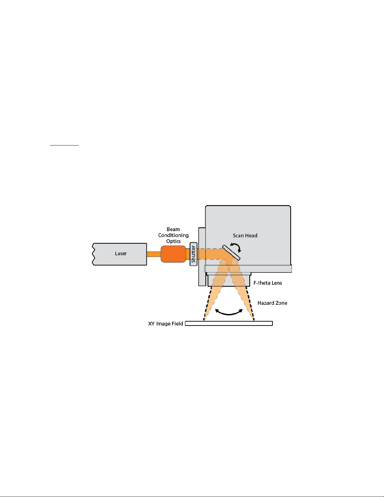
LASER SHUTTER
The MOVIA scan head does not contain a shutter or device to decrease the laser
output power. As each laser is unique, it is your responsibility to install a shutter or
attenuator as required; please refer to US FDA Code of Federal Regulations (CFR)
1040.10 for additional information.
The beam shutter should be installed between the laser and the MOVIA scan head.
Figure 4 shows the laser’s internal and external optical path, the location of the
hazard zones as the optical beam passes through the scan head, and the
recommended location of the shutter.
Cambridge Technology strongly recommends that customers obtain lasers with a
vendor-supplied shutter mechanism. If not possible, consult your laser vendor to
design or acquire a proper safety shutter.
Figure 4: Location of Optical Beam Hazard Zones and Recommended Shutter
Location

3 Installation 3.3 Installation Instructions
MOVIA, 2-Axis Scan Head – User Manual, 1040–0004 Rev. 03 10
3.3 INSTALLATION INSTRUCTIONS
3.3.1 UNPACK THE MOVIA SCAN HEAD
ESD WARNING
Electrostatic discharge and improper handling
can damage MOVIA scan head’s electronics.
•Keep the equipment sealed until it is located at a proper static control
station.
After receiving this product:
•Carefully unpack the contents from the box (verify content with packing list
included with unit).
•Protect the scan head from dust and other contaminants.
•Save the shipping container and packaging material in case you need to
return the unit for service.
3.3.2 MOUNT THE SCAN HEAD
Attach the scan head to the mounting plate using the mounting hardware.
The scan head has 2 metric dowel pin holes and 4 tapped mounting holes. See
Figure 5.

3 Installation 3.3 Installation Instructions
MOVIA, 2-Axis Scan Head – User Manual, 1040–0004 Rev. 03 11
Figure 5: Location of Metric Dowel Pin Holes
3.3.3 ATTACH THE POWER/DATA CABLE TO THE SCAN HEAD
With power off, use the power/data cable to connect the MOVIA scan head to the
system controller and ±15 V power supply. It is recommended that the power
supply voltages are verified before connecting the cable to the head to avoid any
damage.
The usage of cable channels and pin assignments are described in Table 1 and
Table 2.
Table 1: Cable Channel Usage
Channels
Behavior
CLOCK The Clock is transmitted by the position data generator,
20 cycles per frame. The nominal frequency is 2 MHz.
SYNC The frame Sync is a single logical "0" pulse that occurs once
per frame.
It is transmitted by the position data generator one clock
cycle prior to the first bit of the frame.
STATUS The status channel provides error messages when scanner or
servo exceptions occur.

3 Installation 3.3 Installation Instructions
MOVIA, 2-Axis Scan Head – User Manual, 1040–0004 Rev. 03 12
Channels
Behavior
X Y Z DATA The vector controller used to drive the scan head will deliver
set values for X, Y and the optional Z axis.
The X, Y, and Z Data are three 20-bit serial data streams that
consist of one 3-bit control code, one 16-bit position word
(unsigned, MSB first), and an even parity bit.
Improper control codes, parity error, or a missing sync on
the 21st clock cycle will cause the position data word for the
affected channel to be discarded. 001 is the only supported
control code.
GROUND AND
VOLTAGE
The ground and voltage channels provide power to the scan
head.
Table 2: Pin Assignments
Interface
Pin
Connection
Usage
1 -SENDCLK CLOCK
2 -SYNC SYNC
3
-X
DATA
4
-Y
DATA
5 -Z DATA
6 -STATUS STATUS
7
N/C
RESERVED
8
N/C
RESERVED
9 +V VOLTAGE
10 +V VOLTAGE
11
GND
GROUND
12
-V
VOLTAGE
13 -V VOLTAGE
14 +SENDCK CLOCK

3 Installation 3.3 Installation Instructions
MOVIA, 2-Axis Scan Head – User Manual, 1040–0004 Rev. 03 14
3.3.4 ELECTRICAL – POWER SUPPLY REQUIREMENTS
The maximum root mean square (rms) current required is approximately 3 amps,
however peak current demands may approach 10 amps on certain models.
MOVIA scan heads are tuned for ±15 V.
IMPORTANT
Higher voltage than specified
may damage the servo.
•Use the correct voltage for the scan head.
3.3.5 APPLY POWER TO THE SCAN HEAD
Before powering on the overall system, confirm that you have the system
controller (or ScanMaster Controller) configured correctly to work with your laser.
For the ScanMaster Controller (SMC) refer to the SMC Quick Start Guide. Once
you’ve configured the controller to work with your laser and verified the function,
you can power the scan head on.
Perform Alignment of the Laser to the Scan Head To reduce the risk of injury,
please observe the laser safety guidelines in this section.
DANGER
Laser radiation
can cause severe retinal and corneal burns, burns on the skin, and may pose a
fire risk.
•Never stare into the laser’s beam, place any parts of your body in the beam
path, or expose yourself to reflections of beams.

3 Installation 3.3 Installation Instructions
MOVIA, 2-Axis Scan Head – User Manual, 1040–0004 Rev. 03 15
WARNING
Laser radiation
can cause severe retinal and corneal burns, burns on the skin, and may pose a
fire risk.
•Cambridge Technology recommends that you fully enclose and interlock
the zone of hazard to prevent possible beam deflections while the laser is
energized. See Figure 4 for reference.
CAUTION
Laser radiation
can cause severe retinal and corneal burns, burns on the skin, and may pose a
fire risk.
•Cambridge Technology recommends that you use a Class 1 HeNe Laser for
alignment.
If this is not possible, use the available laser's lowest power setting.
CAUTION
Laser radiation
can cause severe retinal and corneal burns, burns on the skin, and may pose a
fire risk.
Using optical instruments with this product increases eye hazard.
•Use optical instruments with caution.
Additional safety requirements may be applicable during initial alignment of the
optical system. Final recommendations and analysis of the system should be
performed by your Laser Safety Officer (LSO), Radiation Safety Officer (RSO), or
safety department of your business or institution.
Follow the laser manufacturer’s instructions to perform the rough alignment of the
laser to the scan head.

3 Installation 3.3 Installation Instructions
MOVIA, 2-Axis Scan Head – User Manual, 1040–0004 Rev. 03 16
3.3.6 INSTALL THE F-THETA LENS AND REQUIRED LENS SPACER
Positioning of the F-Theta lens relative to the scan head is critical for both
scanning performance and safety of the scanning mirrors.
Contact Cambridge Technology for F-Theta lens and lens spacer
recommendations that will eliminate damaging major or minor back reflections
from the optics onto the surface of the mirrors.
While Cambridge Technology can create custom spacers for non-standard lenses,
you may also create a lens spacer. Contact Cambridge Technology for this
product’s model-specific drawing or the 3D Customer CAD model drawing to
create a lens spacer.
When installing the F-Theta lens and spacer, ensure that your laser is powered
down. Thread the spacer fully into the scan head, and then thread the F-Theta lens
fully into the spacer. Failing to do so can lead to back reflections that could
damage the mirrors in the scan head.
3.3.7 PERFORM SCAN HEAD CALIBRATION
DANGER
Laser radiation
can cause severe retinal and corneal burns, burns on the skin, and may pose a
fire risk.
•Never stare into the laser’s beam, place any parts of your body in the beam
path, or expose yourself to reflections of beams.
3 Installation 3.3 Installation Instructions
MOVIA, 2-Axis Scan Head – User Manual, 1040–0004 Rev. 03 17
WARNING
Laser radiation
can cause severe retinal and corneal burns, burns on the skin, and may pose a
fire risk.
•Cambridge Technology recommends that you fully enclose and interlock
the zone of hazard to prevent possible beam deflections while the laser is
energized. See Figure 4 for reference.
CAUTION
Laser radiation
can cause severe retinal and corneal burns, burns on the skin, and may pose a
fire risk.
•Cambridge Technology recommends that you use a Class 1 HeNe Laser for
alignment.
If this is not possible, use the available laser's lowest power setting.
CAUTION
Laser radiation
can cause severe retinal and corneal burns, burns on the skin, and may pose a
fire risk.
Using optical instruments with this product increases eye hazard.
•Use optical instruments with caution.
Each controller manufacturer has a specific process for creating a calibration table
to remove any distortions caused by the lens and position of the scan head
relative to the work area. The controller uses information in the correction table to
pre-process the command data to remove these distortions.
Contact Cambridge Technology for correction tables that provide common scan
head and lens configurations and are compatible with many commercial
Table of contents


