Jireh STIX User manual

BG0088 Rev 03.4
Manual Magnetic TOFD Scanner

PAGE i of iv BG0088 Rev 03.4
SAFETY WARNINGS / PRECAUTIONS
DANGER! The STIX is designed for a specic use. Using the STIX
outside of its intended use could cause damage to the product. Read and
understand this manual before using.
KEEP THIS MANUAL – DO NOT LOSE
THIS MANUAL IS PART OF THE STIX AND MUST BE RETAINED FOR THE LIFE OF THE
PRODUCT. PASS ON TO SUBSEQUENT OWNERS.
Ensure any amendments are incorporated with this document.
WARNING! Do NOT operate scanner in an explosive environment.
Do NOT operate scanner in the presence of volatile substances.
The WEEE symbol indicates that the product must not be disposed of as
unsorted municipal waste, but should be collected separately.
(see “Disposal” on page 15)
Jireh Industries Ltd.
53158 Range Road 224
Ardrossan, Alberta, Canada
T8E 2K4
Phone: (780) 922-4534
Fax: (780) 922-5766
jireh-industries.com
DISTRIBUTOR: MANUFACTURER:
WARNING! Can be harmful to pacemaker and ICD wearers. Stay
at least 25 cm (10 in) away.

PAGE ii of iv
Chapter
1
Introduction 1
1.1. Product information 1
1.1.1. Intended use 1
1.1.2. Performance specifications 1
1.1.3. Operating environment 1
1.1.4. Environmental Sealing 1
1.2. Definition of symbols 1
1.3. Hardware 2
1.3.1. Included tools 2
1.3.2. Optional tools 2
1.3.3. Maintenance 2
Chapter
2
Configurations 3
2.1. Two Probe TOFD 3
2.2. Two Probe TOFD Cantilever 3
Chapter
3
Operation 4
3.1. STIX setup on a scan surface 4
Chapter
4
Component Overview 7
4.1. Handle 7
4.2. Wheel Block 8
4.2.1. Wheel Installation 8
4.2.2. Wheel Removal 8
4.2.3. Ratchet Lever 9
4.3. Frame Bar 9
4.4. Trailing Encoder 10
4.5. Pivot Buttons 10
4.6. Spring Loaded Probe Holder 11
4.6.1. Probe Holder Setup 11
4.7. Magnetic Wheel Kit 13
4.8. Pre-Amp Bracket 14
TABLE OF CONTENTS

PAGE iii of iv BG0088 Rev 03.4
Chapter
5
Service and Support 15
5.1. Troubleshooting 15
5.2. Technical Support 15
5.3. Disposal 15
Chapter
6
Spare Parts 16
6.1. Scanner 16
6.2. Kit Components 17
6.2.1. Encoder Connector Type 18
6.3. Accessories 18
6.3.1. Magnetic Wheel Kit 18
6.3.2. Pre-Amp Bracket 18
6.3.3. Cable Management 19
6.4. Probe Holders 20
6.4.1. Slip Joint Probe Holder Parts 20
6.4.2. Vertical Probe Holder Parts 21
6.5. Probe Holder Components 22
6.5.1. Spring Loaded Arm Style 22
6.5.2. Slip Joint and Vertical Probe Holder Arm Style 22
6.5.3. Slip Joint and Vertical Probe Holder Yoke Style 22
6.5.4. Swing Arm Style 22
6.5.5. Pivot Button Style 23
6.6. Variable Components 23
6.6.1. Frame Bars 23
Chapter
7
Limited Warranty 24

PAGE iv of iv

PAGE 1 of 25 BG0088 Rev 03.4
CHAPTER 1
INTRODUCTION
1.1. Product information
1.1.1. Intended use
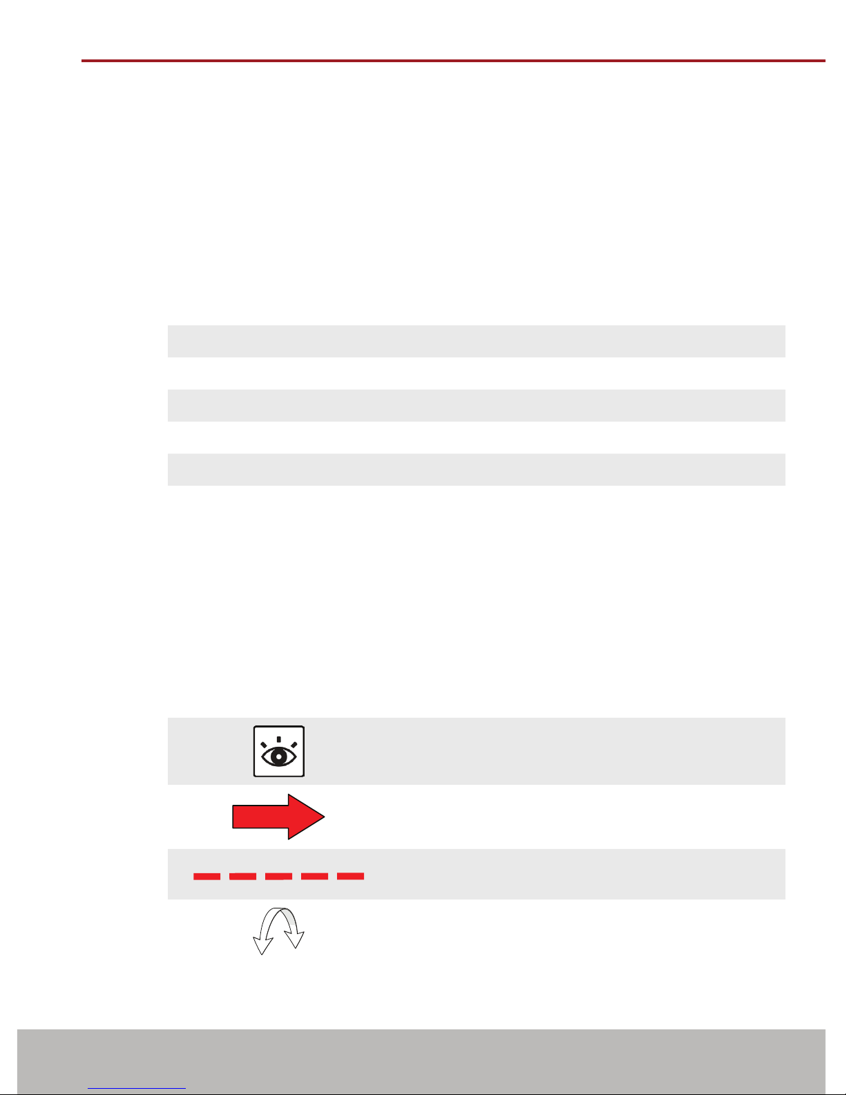
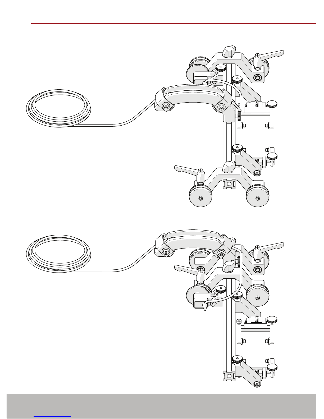
The STIX is a manual magnetic scanner with trailing encoder and magnetic
wheels. It is designed to translate two TOFD probes around ferrous piping and
vessels.
1.1.2. Performance specications
Minimum Maximum
Pipe/Tube Range Outer Diameter 10.2 cm (4 in) Flat
Pipe/Tube Range Inner Diameter Flat 152.4 cm (60 in)
Umbilical Length (Standard Kit) 5 m (16.4 in)
X Axis Encoder Resolution 9.05 counts/mm (230.0 counts/inch)
1.1.3. Operating environment
The STIX is designed for use in industrial environments that are between
-20°C (-4°F) and 50°C (122°F).
1.1.4. Environmental Sealing
Dust tight, water tight (not submersible).
1.2. Denition of symbols
Instructions to ‘look here’ or to ‘see this part’
Denotes movement. Instructing user to carry out
action in a specied direction.
Indicates alignment axis, can also indicate
insertion or movement of parts.
Alerts user that view has changed to a reverse
angle.

PAGE 2 of 25
1.3. Hardware
1.3.1. Included tools
The 3 mm hex driver (Fig. 1) is sufcient for all typical operations and
adjustments of the STIX. The 3/8 in wrench (Fig. 2) is used to remove and
install buttons on the probe holders.
1.3.2. Optional tools
Some specialized adjustments require tools that are not included with this kit.
1.3.3. Maintenance
General cleaning of components is important to keep your system working
well. All components that have no wiring or cables are completely waterproof.
Components can be washed with warm water, dish soap and a medium bristle
brush.
Before using the scanner, ensure all connectors are free of water and
moisture.
NOTE: All components with wiring, cables or electrical connections are splash
proof. However, these components are NOT submersible.
NOTE: Never use strong solvents or abrasive materials to clean your scanner
components.
Fig. 1 - 3 mm hex driver Fig. 2 - 3/8 in wrench
Fig. 3 - 1.5 mm hex
wrench
Fig. 4 - 2 mm
hex wrench
Fig. 5 - 2.5 mm
hex wrench
Fig. 6 - 3 mm
hex wrench

PAGE 3 of 25 BG0088 Rev 03.4
CHAPTER 2
CONFIGURATIONS
2.1. Two Probe TOFD
2.2. Two Probe TOFD Cantilever
Fig. 7 - Two probe TOFD conguration
Fig. 8 - Two probe TOFD cantilever conguration

PAGE 4 of 25
CHAPTER 3
OPERATION
3.1. STIX setup on a scan surface
1. Mount TOFD wedges to the probe
holders (see Spring Loaded Probe
Holder on page 11).
TIP: Mounting the wedges to the
spring loaded probe holders
can be easier when the probe
holders are separate from the
STIX frame bar.
2. Assemble the appropriate conguration (Fig. 10). Attach the spring loaded
probe holders to the frame bar where appropriate.
3. Ensure the brakes are locked on the wheel blocks
(see Ratchet Lever on page 9).
Fig. 9 - Mount wedges to probe holders
Fig. 10 - Attach spring loaded probe holders to appropriate conguration

PAGE 5 of 25 BG0088 Rev 03.4
4. Route cables and hoses through the handle (Fig. 11).
5. Place the congured STIX on the scan surface (Fig. 12).
TIP: Use caution when placing equipment on the scan surface. The magnetized
wheels can cause the assembly to lurch towards the metal suddenly.
Fig. 11 - Use handle for cable management
Fig. 12 - Place on scan surface

PAGE 6 of 25
6. The spring loaded probe holders are designed to maintain wedge contact with
the scan surface (Fig. 13), as well, the encoder is designed to maintain contact
pressure on the scan surface for accurate reading.
7. Release the both brakes to begin scanning procedure.
Fig. 13 - Prepared for scanning

PAGE 7 of 25 BG0088 Rev 03.4
CHAPTER 4
COMPONENT OVERVIEW
4.1. Handle
Used to operate the scanner as well as provide a means of cable management. To
install and setup the handle, follow these steps:
1. Loosen the handle’s knob
and mount to a frame bar
(Fig. 14).
2. Tighten handle knob
to fasten handle to the
frame bar (Fig. 15).
TIP: Slightly loosen
handle knob and
slide handle along
frame bar for
alternate placement
when required.
3. Open velcro straps and
place cables and hoses
in the handle (Fig. 16).
Reattach the velcro
straps to secure cables
and hoses within the handle.
1
2
Fig. 14 - Attach handle to frame bar Fig. 15 - Tighten handle knob
Fig. 16 - Handle provides cable management

PAGE 8 of 25
4.2. Wheel Block
The wheel block provides stability and braking to the STIX system.
The ratchet lever located on the wheel block operates a brake
(see Ratchet Lever on page 9).
Attach a wheel block by loosening the black wing knob and sliding the wheel
block’s dovetail nut onto a frame bar (Fig. 17). Tighten the black wing knob (Fig. 18).
4.2.1. Wheel Installation
1. Locate and position the thread-
ed side of the magnetic wheel to
the outside of the scanner.
2. Screw the magnetic wheel along
the entire length of the axle.
3. Grip the magnetic wheel by
hand and using the supplied
3 mm hex driver (Fig. 1), tighten
the magnetic wheel to the axle
(Fig. 20).
4.2.2. Wheel Removal
1. Tightly grip the magnetic wheel
to be removed. Using the 3 mm
hex driver, loosen the magnetic
wheel from the axle (Fig. 19).
TIP: When the brake is engaged
and the scanner is moved,
the wheels may loosen from
the axle. Grip the magnetic
wheel tightly and retighten
the axle with the 3 mm hex
driver.
1
2
Fig. 17 - Attach to frame bar Fig. 18 - Tighten wing knob
Fig. 19 - Wheel removal
Fig. 20 - Wheel installation

PAGE 9 of 25 BG0088 Rev 03.4
4.2.3. Ratchet Lever
The rachet levers lock the brakes of the STIX system. Occasionally,
movement of the lever’s locking position is required. The lever placement can
be adjusted by following these steps:
1. Pull the ratchet lever away from the base of which it is connected (Fig. 21).
2. Continue to pull while rotating the lever in the appropriate direction
(Fig. 22).
3. Release the lever and utilize the new tightening position (Fig. 23).
4.3. Frame Bar
Frame bars (Fig. 24) are used to mount
probe holders, probe positioning
systems and other accessories (see
Frame Bars on page 23).
Frame bars are available in a variety of
lengths.
WARNING! MAGNETIC MATERIAL. The
stabilizer wheel uses a magnetic wheel. People with
pacemakers or ICD’s must stay at least 25 cm (10 in) away.
Fig. 21 - Pull ratchet handle Fig. 22 - Rotate handle Fig. 23 - Tighten handle
Fig. 24 - Frame bar

PAGE 10 of 25
4.4. Trailing Encoder
The spring loaded encoder wheel provides vertical travel while maintaining contact
pressure to the scan surface. To install the encoder follow these steps:
1. Loosen the encoder’s dovetail jaw and mount to the frame bar (Fig. 25).
2. Tighten the encoder knob (Fig. 26).
3. Spring tension maintains encoder contact with the scan surface (Fig. 27).
4.5. Pivot Buttons
Available in a variety of shapes and
sizes tting various wedge dimensions.
Use the supplied 3/8 in wrench (Fig. 2) to
remove and install pivot buttons (Fig. 28).
2
1
Fig. 25 - Attach to frame bar Fig. 26 - Tighten knob Fig. 27 - Place on scan surface
1
2
Fig. 28 - Pivot buttons

PAGE 11 of 25 BG0088 Rev 03.4
4.6. Spring Loaded Probe Holder
AFrame Bar
BProbe Holder Adjustment Knob
CYoke
DProbe Holder Arm Adjustment
Knob
EProbe Holder Arm
FPivot Button
GArm Clamp Screw
4.6.1. Probe Holder Setup
To mount a TOFD wedge in the spring loaded probe holder, follow these steps:
1. Rotate the probe holder adjustment knob and attach the probe holder to a
frame bar (Fig. 30).
2. Use the probe holder adjustment knob to position the probe holder along
the frame bar (Fig. 31).
2
A
G
B
C
F
E
D
Fig. 29 - Spring loaded probe holder
Fig. 30 - Attach to frame bar
2
1
Fig. 31 - Position on frame bar
1
2

PAGE 12 of 25
TIP: Wedge pivoting may be impeded when utilizing pivot buttons closer to the
yoke. (see Pivot Buttons on page 10)
3. Loosen the probe holder arm adjustment knob (Fig. 32) and remove outer
probe holder arm from the yoke.
4. Adjust inner probe holder arm as required to best centre the probe on the
yoke’s pivot axis (Fig. 32).
TIP: The probe holder yoke can ac-
commodate different probe and
wedge sizes of varying widths. It
is best to centre the wedge with
the yoke’s pivot axis to reduce
wedge tipping when scanning.
Position the inner probe holder
arm accordingly with the centre
of the yoke (Fig. 33).
5. Position the wedge on the inner
probe holder arm (Fig. 33).
6. Slide outer probe holder arm along
the yoke pinching the wedge in
place (Fig. 33).
7. Tighten the probe holder arm adjust-
ment knob (Fig. 34).
Fig. 32 - Adjust inner probe holder arm Fig. 33 - Place wedge and outer arm
Fig. 34 - Tighten probe holder knob

PAGE 13 of 25 BG0088 Rev 03.4
4.7. Magnetic Wheel Kit
WARNING! MAGNETIC MATERIAL. The
magnetic wheel kit produce a magnetic eld which may
cause failure or permanent damage to items such as watches,
memory devices, CRT monitors, medical devices or other
electronics. People with pacemakers or ICD’s must stay at least
25 cm (10 in) away.
Two sets of the magnetic wheels can be used with the STIX, thus doubling the
magnetic force.
NOTE: Magnetic wheels may lose their magnetic properties if heated above
175° F (80° C).
To install additional magnetic wheels, follow these steps:
1. Ensure the four existing wheels are tight (see Wheel Installation on page 8)
2. On the magnetic wheel to be attached, locate the threaded side of the
magnetic wheel, orient this threaded side towards the scanner.
3. By hand, grip the wheel already attached to the wheel block. Overcome the
magnetic resistance to screw the additional wheel to the axle of the wheel
block (Fig. 35).
4. Hold steady the magnetic wheel closest to the scanner body, insert the 3 mm
hex driver into the axle and tighten the additional wheel (Fig. 36).
TIP: To remove additional wheels, reverse these steps.
Fig. 35 - Screw on additional magnetic wheel Fig. 36 - Tighten with 3 mm hex driver

PAGE 14 of 25
4.8. Pre-Amp Bracket
The pre-amp bracket mounts to any
dovetail groove to hold a pre-amp.
Compatible with most standard pre-
amps, use the adjustable screw mounting
channel on the bottom of the bracket to
attach a pre-amp. The pre-amp bracket
may also be ordered with velcro straps
which are used to hold the pre-amp.
Fig. 37 - Insert velcro straps
1
Fig. 38 - Place pre-amp and wrap velcro
2
Fig. 39 - Mount bracket on a frame bar
3

PAGE 15 of 25 BG0088 Rev 03.4
CHAPTER 5
SERVICE AND SUPPORT
5.1. Troubleshooting
Problem Possible Cause Solution
1. Encoder not
functioning.
Instrument not
properly setup.
Refer to instrument’s documentation
regarding proper setup.
Issue with encoder. Contact Jireh Industries for repair (see Jireh
Industries Ltd. on page i).
2. Insufcient
probe
contact.
Scanner not set
properly.
Recongure the scanner as per instructions
(see Spring Loaded Probe Holder on page 11).
3. Magnetic
wheels
become
loose.
Brakes are engaged. Ensure the brakes are unlocked when using
the scanner (see Wheel Block on page 8).
5.2. Technical Support
For technical support contact Jireh Industries (see “Jireh Industries Ltd.” on page i)
5.3. Disposal
WEEE Directive
In accordance with European Directive on Waste Electrical and
Electronic Equipment (WEEE), this symbol indicated that the
product must not be disposed of as unsorted municipal waste,
but should be collected separately. Refer to Jireh Industries for
return and/or collection systems available in your country.
Other manuals for STIX
5
Table of contents
Other Jireh Scanner manuals