NovaStar J6 User manual


J6 Seamless Switcher User Manual
Copyright © 2019 Xi’an NovaStar Tech Co., Ltd. All Rights Reserved.
No part of this document may be copied, reproduced, extracted or transmitted in any form or by any means without the prior written
consent of Xi’an NovaStar Tech Co., Ltd.
Trademark
is a registered trademark of Xi’an NovaStar Tech Co., Ltd.
Statement
You are welcome to use the product of Xi’an NovaStar Tech Co., Ltd. (hereinafter referred to as NovaStar). This document is
intended to help you understand and use the product. For accuracy and reliability, NovaStar may make improvements and/or changes
to this document at any time and without notice. If you experience any problems in use or have any suggestions, please contact us
via contact information given in document. We will do our best to solve any issues, as well as evaluate and implement any
suggestions.

J6 Seamless Switcher User Manual
Contents
1 Overview..............................................................................................................................................................................................1
Introduction....................................................................................................................................................................................1
Features..........................................................................................................................................................................................1
2 Appearance...........................................................................................................................................................................................3
Front Panel.....................................................................................................................................................................................3
Rear Panel......................................................................................................................................................................................4
Dimensions....................................................................................................................................................................................5
3 Applications..........................................................................................................................................................................................6
4 Menu Operations..................................................................................................................................................................................7
Operation Instructions....................................................................................................................................................................7
Home Screen..................................................................................................................................................................................7
Screen Settings...............................................................................................................................................................................9
4.3.1 Output Mode .......................................................................................................................................................................9
4.3.2 Screen Layout....................................................................................................................................................................10
4.3.3 Output Settings..................................................................................................................................................................10
4.3.4 Output Connector Settings ................................................................................................................................................11
Layer Settings..............................................................................................................................................................................11
4.4.1 Layer Layout .....................................................................................................................................................................11
4.4.2 BKG Settings.....................................................................................................................................................................11
4.4.3 Layer Settings....................................................................................................................................................................13
Preset Settings..............................................................................................................................................................................13
Input Settings...............................................................................................................................................................................14
Display Control............................................................................................................................................................................14
Test Pattern ..................................................................................................................................................................................15
MVR Settings ..............................................................................................................................................................................15
Advanced Settings......................................................................................................................................................................16
4.10.1 System Mode...................................................................................................................................................................16
4.10.2 Sync Mode.......................................................................................................................................................................16
4.10.3 Fn Settings.......................................................................................................................................................................17
4.10.4 Go Homepage..................................................................................................................................................................17
4.10.5 Factory Reset...................................................................................................................................................................17
4.10.6 HDCP..............................................................................................................................................................................18
4.10.7 Diagnostics......................................................................................................................................................................18
4.10.8 Hardware Version............................................................................................................................................................18
4.10.9 About Us..........................................................................................................................................................................18
Communication Settings............................................................................................................................................................18
Language ...................................................................................................................................................................................19
5 V-Can Control.....................................................................................................................................................................................20
6 C1 Control..........................................................................................................................................................................................21
7 Troubleshooting..................................................................................................................................................................................24
8 Specifications .....................................................................................................................................................................................25

J6 Seamless Switcher User Manual
www.novastar.tech
1
1 Overview
Introduction
The J6 is a NovaStar high-performance seamless switcher that integrates video processing, screen mosaic, transition
effects and multi-screen display capabilities. The J6 offers powerful video signal receiving and processing abilities, and
supports up to 8 inputs with the resolutions up to 4K×2K@30Hz and 6 layers. Besides, this product supports two system
modes: Splicer and Switcher. When it is in Splicer mode, a maximum of 4 DVI output connectors can be used together
for output, which can realize an up to 8KK loading capacity of each J6 unit. When it is in Switcher mode, a maximum of
2 DVI output connectors can be used together for output, which can realize an up to 4KK loading capacity of each J6
unit.
Based on powerful FPGA platform, the J6 supports input and output EDID management and color adjustment, seamless
transition of a variety of input sources, as well as fade and other transition effects, bringing you a more flexible and rich
visual experience.
What's more, the J6 is equipped with NovaStar V-Can smart control software and C1 event controller, allowing for a rich
screen mosaic effect via V-Can, C1 or front panel operations. With excellent image quality, ultra-large loading capacity
and flexible operation modes, the J6 can be widely used in conference reports, exhibition centers, stage control and other
application scenarios.
Features
Compatible with industry-standard video input connectors
−DVI connector: 1920×1080@60Hz input
−HDMI 1.3 connector: 1920×1080@60Hz input
−3G-SDI connector: 1920×1080@60Hz input
−DP 1.1 connector: 4K×2K@30Hz input
−HDMI 1.4 connector: 4K×2K@30Hz input
4 groups (2 connectors in each group) of DVI output connectors of a single J6 unit for mosaic output
Each group includes a main connector and a backup connector. Amaximum of 4 connectors can be used for mosaic
output. The mosaic layout can be 4×1, 1×4 or 2×2. The maximum loading capacity can reach 9,200,000 pixels
and the maximum mosaic width can be up to 15360 pixels.
Dual system modes
The J6 supports both Splicer and Switcher modes, which can meet different application requirements.
Multiple layer display
The J6 supports up to six 4K×2K layers with random layout. Each layer supports cross connector output.
HDMI connector for output monitoring
−Supports monitoring of a single input source, PVW or PGM.
−Supports monitoring of all input sources, PVW and PGM.
−Supports displaying of input resolution and refresh rate.
Display control function
Allows you to black out or freeze the screen by simply clicking one button.
EDID management
Supports input resolution management for DVI, HDMI and DP connectors.
Transition effects
In Splicer mode, the J6 supports setting of transition effect for source switching. In Switcher mode, the J6 supports
setting of Take effect and effect duration.
BKG capturing
In Switcher mode, the J6 supports capturing of input source and PGM, and the captured image can be used as BKG.
BKG settings

J6 Seamless Switcher User Manual
www.novastar.tech
2
In Switcher mode, the J6 supports both image BKG and pure color BKG. You can save at most 6 BKG images.
Input color, layer color and output color adjustable
Preset management
You can create at most 10 custom presets and load the preset simply by clicking one button.
Layer layout management
The J6 is built-in with 7 layer layouts. You can load one of the layer layouts to quickly lay out the layers.
Multiple operation modes
You can operate the J6 via its front panel, the V-Can smart control software or C1 event controller.
Visualized color LCD screen and distinct button indicators on front panel, simplifying system control operations

J6 Seamless Switcher User Manual
www.novastar.tech
3
2 Appearance
Front Panel
No.
Button
Description
ON/OFF
button
Press ON to power on the device.
Press OFF to power off the device.
Layer
buttons
Press a layer button to open the corresponding layer and enter the layer settings menu, or press
the layer button to input the corresponding number on the button.
Button indicator descriptions:
On: The layer is open, and the input source is accessed normally.
Dim: The layer is open, but the input source is abnormal.
Off: The layer is not opened.
Flashing: The layer is being edited.
On the home screen, hold down the layer button for 2s or longer to close the opened layer.
Input
source
buttons
Press an input source button to quickly select an input source for the layer.
Button indicator descriptions:
On: The input source is accessed and in normal use.
Dim: The input source is accessed but not in use.
Off: The input source is not accessed.
LCD
screen
Display current device status and settings menu.
Knob
On the home screen, press the knob to enter the operation menu screen.
On the operation menu screen, rotate the knob to select a menu item, and press the knob to
confirm the selection or enter the submenu.
When a menu item with parameters is selected, rotate the knob to adjust the parameters.
Please note that after adjustment, you need to press the knob again to confirm the adjustment.
Freeze
button
Freeze or unfreeze the output image.
Button indicator descriptions:
On: The output image is frozen.
Off: The output image is unfrozen.
ESC
button
Press the button to exit the current menu or cancel the operation.
Function
buttons
PRESET: Enter the preset menu.
BKG: Enable or disable the BKG function.
FTB/TEST: Press the button to make the screen fade to black and press the button again to
exit the FTB mode. Hold down the button for 2s or longer to enter the test pattern menu.

J6 Seamless Switcher User Manual
www.novastar.tech
4
No.
Button
Description
FN/TAKE: The function of this button varies in different system modes (Splicer and
Switcher).
−In Splicer mode, press the button to enter the menu of the function that has been
customized for FN button, Hold down the button to enter the FN settings menu.
−In Switcher mode, press the button to send PVW to PGM.
Rear Panel
Input
No.
Connector
Description
Input-A
DP 1.1
Input resolution up to 3840×2 160@30Hz and custom EDIDs
Supports HDCP 1.3.
Can be changed to HDMI 1.4 input card.
Input resolution up to 3840×2160@30Hz and downward compatible
Supports HDCP 1.4.
Input-B
3G-SDI
Input resolution up to 1920×1080@60Hz and downward compatible
Supports 3G-SDI loop output.
Input-C
HDMI 1.3
Input resolution up to 1920×1080@60Hz and downward compatible
Supports HDCP 1.4.
Can be changed to DVI input card.
Input-D
DVI
Input resolution up to 1920×1080@60Hz, other VESA standard resolutions and
custom EDIDs supported, downward compatible
Supports HDCP 1.4.
Can be changed to HDMI 1.3 input card.
Input-E
Input-F
-
The J6 has two standard versions.
Version I: Input-G is DP 1.1 input card, which supports up to
3840×2160@30Hz video source input and custom EDIDs. When it is changed to
HDMI 1.4 input card, the Input-F is unavailable.
Version II: Input-F and Input-G are DVI input cards, which support up to
1920×1080@60Hz and other VESA-standard compliant video source inputs and
downward compatibility as well as custom EDIDs. The two connectors both can
be changed to HDMI 1.3 input cards.
Input-G
DP 1.1 /
DVI
Input-H
3G-SDI
Input resolution up to 1920×1080@60Hz and downward compatible
Supports 3G-SDI loop output.
Output
No.
Connector
Description
DVI
8
4 groups (2 connectors in each group) of DVI output connectors can be used for
mosaic output.
Each group includes a main connector and a backup connector.
The J6 supports dual-link DVI output mode. When the output is set to dual-link
mode, DVI1 and DVI3 are used as output connectors, while DVI2 and DVI4 are
unavailable.

J6 Seamless Switcher User Manual
www.novastar.tech
5
Monitor
1
An HDMI connector is used as monitoring connector to monitor all input sources,
single input source, PVW and PGM.
Control
No.
Connector
Description
ETHERNET
1
Communicate with PC or connect to the network.
USB (Type-B)
1
Connect to the PC for device control.
USB (Type-A)
1
A reserved connector
Overall Specifications
No.
Connector
Description
Power
1
AC100V-240V–50/60Hz
Dimensions
Unit: mm


J6 Seamless Switcher User Manual
www.novastar.tech
7
4 Menu Operations
Operation Instructions
Knob
On the home screen, pressing the knob enters the operation menu screen.
On the operation menu screen, rotating the knob selects a menu item, and pressing the knob confirms the selection
or enters the submenu.
When a menu item with parameters is selected, you can rotate the knob to adjust the parameters. Please note that
after adjustment, you need to press the knob again to confirm the adjustment.
ESC
Press the button to exit the current menu or cancel the operation.
Button Lock and Unlock
Hold down the knob and ESC button simultaneously to lock or unlock all the buttons.
Home Screen
After the device is powered on, the home screen of the LCD screen is shown in Figure 4-1 and the home screen
descriptions are shown in Table 4-1.
Figure 4-1 Home screen
Table 4-1 Home screen descriptions
No.
Area
Description
NovaStar J6
192.168.0.10
Novastar J6: Device name
192.168.0.10: Device IP address
Input source
Display the input source status.
Transparent: The input source is not accessed.
Semi-transparent: The input source is accessed, but not in use.
Highlight: The input source is accessed and in use.
Layer
Display the layer status and its input source.
Transparent: The layer is not opened.
Semi-transparent: The layer is opened, but the input source is not accessed.
Highlight: The layer is opened and the input source is accessed.
Screen layout
and screen
Display the current screen layout and resolution.
In Spicer mode, the supported screen layouts are 1×1, 1×2, 2×1, 1×3, 3×1, 2×2, 1×4

J6 Seamless Switcher User Manual
www.novastar.tech
8
No.
Area
Description
resolution
and 4×1.
In Switcher mode, the supported screen layouts are 1×1, 1×2 and 2×1.
Output
resolution
The output resolution of a single output connector
Device
connection
status
Indicate the status of the connection between the control PC or C1 event controller and
the device.
: The device is connected to the control PC via USB port.
: The device is connected to the control PC or C1 event controller via Ethernetport.
: The device is not connected to the control PC or C1 event controller.
BKG
Indicate the BKG status.
: The BKG function is turned on.
: The BKG function is turned off.
Transition effect
: Fade effect
: Cut effect
Display control
: The screen display is normal.
: The screen is faded to black.
: The screen is frozen.
: The test pattern. When the test pattern function is used via the control PC or C1
event controller, the test pattern icon will be displayed on the device LCD screen.
Button locking
status
Hold down the knob and ESC button simultaneously for 5 seconds or longer to lock or
unlock all the buttons.
When the device is connected to the V-Can or C1 event controller, the front panel will be
locked automatically and the lock icon will be shown.
: The front panel buttons are locked.
: The front panel buttons are unlocked.
Genlock status
Indicate the Genlock status.
: The Genlock function is turned on and locked.
: The Genlock function is turned on and to be locked.
: The Genlock function is abnormal or the Genlock source is lost.
: The Genlock function is turned off.
System mode
The J6 supports two system modes: Splicer and Switcher.
: Switcher mode
: Splicer mode
On the home screen, press the knob to enter the device main menu screen which is shown in Figure 4-2.

J6 Seamless Switcher User Manual
www.novastar.tech
9
Figure 4-2 Main menu
Screen Settings
On the main menu screen, rotate the knob to select Screen Settings where you can set the output mode, screen layout,
output resolution as well as the width and height of the screen area loaded by a certain output connector.
Figure 4-3 Screen layout
4.3.1 Output Mode
The four group of DVI connectors of the J6 can be configured as single link DVI output or dual link DVI output. When
the output mode is different, the connection of the device output connector is different.
When the Output Mode is set to SL, the DVI connector is set to single link mode. The connector connection will
vary according to the System Mode of the J6.
−When the System Mode is Splicer, DVI 1, DVI 2, DVI 3 and DVI 4 are all used as output connectors.
−When the System Mode is Switcher, DVI 1 and DVI 2 are used as output connectors, while DVI 3 and DVI 4
are unavailable.
When the Output Mode is set to DL, the DVI connector is set to dual link mode. The connector connection will
vary according to the System Mode of the J6.
−When the System Mode is Splicer, DVI 1 and DVI 3 are used as output connectors, while DVI 2 and DVI 4 are
unavailable.
−When the System Mode is Switcher, DVI 1 is used as output connector, DVI 3 is used as PVW monitoring
connector, while DVI 2 and DVI 4 are unavailable.
Figure 4-4 Output mode

J6 Seamless Switcher User Manual
www.novastar.tech
10
4.3.2 Screen Layout
Screen layout is the screen mosaic mode. The screen layout will vary according to Output Mode and System Mode.
System mode: Splicer
−When the Output Mode is SL, the following 8 screen layouts are supported.
−When the Output Mode is DL, the following 3 screen layouts are supported.
System mode: Switcher
−When the Output Mode is SL, the following 3 screen layouts are supported.
−When the Output Mode is DL, only 1×1 screen layout is supported.
Figure 4-5 Screen layout
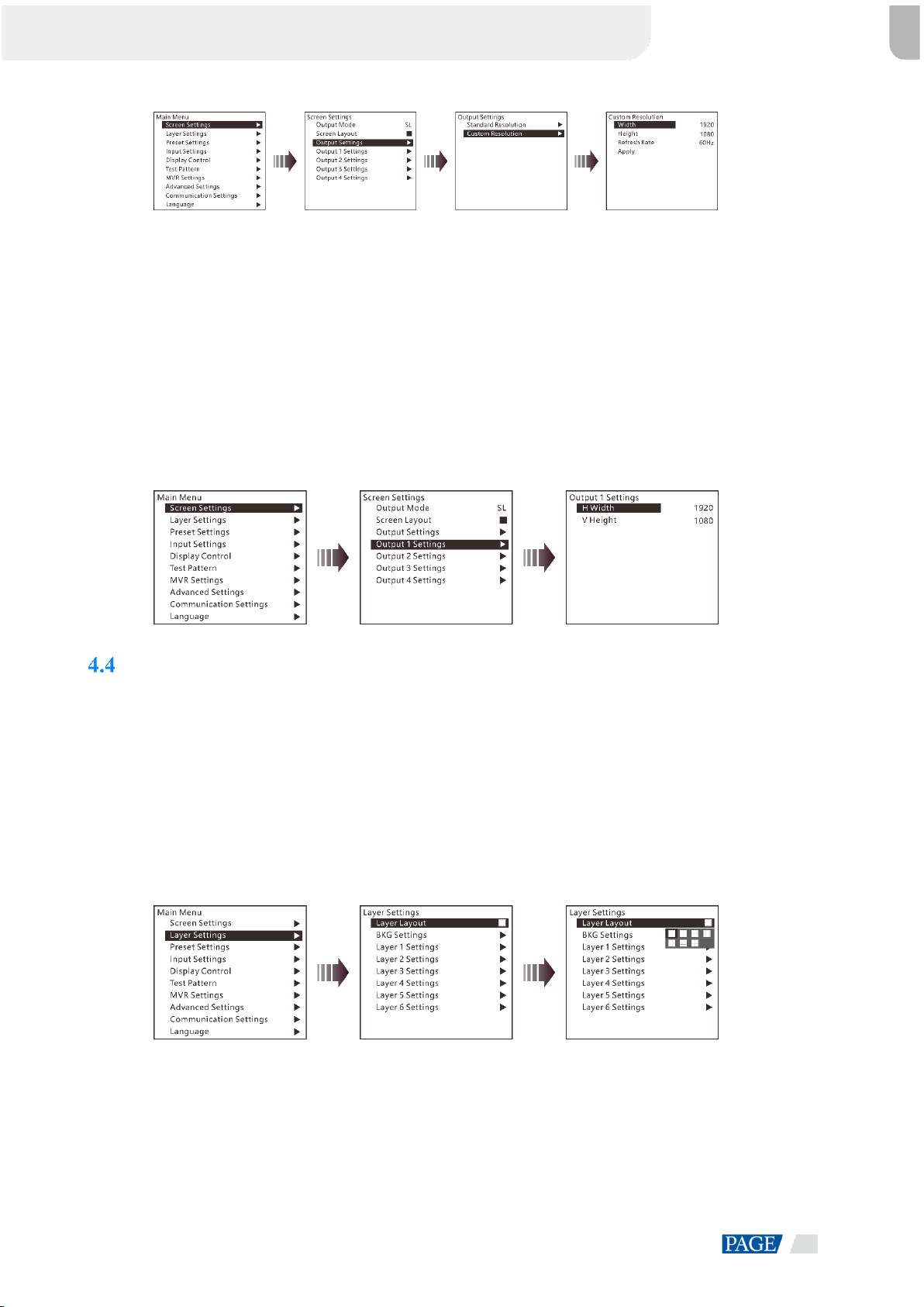
4.3.3 Output Settings
Output settings allow you to set the output resolution of the DVI output connector. Standard resolutions and custom
resolutions are both supported.
Output Mode: SL
(Default) Output resolution is 1920×1080. Refresh rate is 60 Hz. Custom width range is 600–3840. Custom
height range is 600–3840. Refresh rate range is 24 Hz–120 Hz.
Output Mod: DL
(Default) Output resolution is 1920×1080. Refresh rate is 60 Hz. Custom width range is 1200–7680. Custom
height range is 600–3840. Refresh rate range is 24 Hz–120 Hz.
Figure 4-6 Standard resolution
J6 Seamless Switcher User Manual
www.novastar.tech
11
Figure 4-7 Custom resolution
Rotate the knob to select Standard Resolution and rotate the knob again to select a standard resolution, then press the
knob to confirm the selection. Rotate the knob to select Custom Resolution and rotate the knob again to adjust the value
or use the number buttons on the front panel to enter a value. After the resolution is set, rotate the knob to select Apply to
make the settings take effect.
4.3.4 Output Connector Settings
Output 1/2/3/4 settings allow you to set the width and height of the screen area loaded by an output connector. When two
or more connectors are used together for horizontal mosaic output, the height change for one connector will apply to both
or all connectors, but the width for a single connector can be changed. When two or more connectors are used together
for vertical mosaic output, the width change for one connector will apply to both or all connectors, but the height for a
single connector can be changed.
Figure 4-8 Output connector settings
Layer Settings
The J6 supports one BKG and six layers. You can set the layer layout simply by selecting a layout from Layer Layout or
set the parameters for each layer.
On the main menu screen, rotate the knob to choose Layer Settings > Layer Layout to enter the layer layout settings
screen.
4.4.1 Layer Layout
The J6 provides 7 layer layouts. You can select a desired layout in Layer Layout, and then all the layers will together fill
the screen. The layer quantity, size and position will be set automatically according to the selected layout.
Figure 4-9 Layer layout
4.4.2 BKG Settings
When the System Mode is Switcher, the J6 supports BKG settings. You can load an image file from the control PC,
capture an input source image displayed on the screen or select a pure color as the BKG image. BKG has the lowest
priority and fills the whole screen.
On the layer settings screen, rotate the knob to select BKG Settings and press the knob to enter the BKG settings screen.
You can turn on or turn off the BKG function.

J6 Seamless Switcher User Manual
www.novastar.tech
12
Figure 4-10 BKG
BKG Image
The J6 supports up to 6 BKG images. You can load an image file from the control PC or C1 event controller, capture an
input source image displayed on the screen or select a pure color as the BKG image.
1. On the BKG settings screen, rotate the knob to choose Type > Image.
2. Then rotate the knob to select Image and press the knob to enter the BKG image selection screen.
3. Rotate the knob to select a BKG image and press the knob to apply the selected BKG image to PVW.
Figure 4-11 BKG image
Pure Color BKG
The J6 supports pure color BKG. When the BKG type is Pure Color, you need to set the individual R, G and B value for
the pure color BKG.
Figure 4-12 Pure color BKG
BKG Capture
You can capture the current display image on PGM or the current frame of the select input source, and save the captured
image as the BKG image.
Figure 4-13 BKG capture
1. On the BKG settings screen, rotate the knob to choose Capture > Source to select an input source or PGM.
2. Rotate the knob to select Save As to save the captured BKG image to the specified location.
3. Rotate the knob to select Capture and press the knob, then the system will automatically capture the current frame of
the image and save the captured BKG image to the specified location.
Note:
If a BKG image already exists in the selected location, the captured BKG image will overwrite the existing one.

J6 Seamless Switcher User Manual
www.novastar.tech
13
4.4.3 Layer Settings
The J6 supports 6 layers. The input source, size, position, priority and input cropping of each layer can be set. Here take
Layer 1 as an example to illustrate.
Figure 4-14 Layer settings
Status: Turn on or turn off the layer.
Input Source: Set the input source for the layer.
H Width: Adjust the layer width. The default value is 800.
V Height: Adjust the layer height. The default value is 600.
Initial X: Adjust the initial horizontal coordinate of the layer. The default value is 0.
Initial Y: Adjust the initial vertical coordinate of the layer. The default value is 0.
Priority: Set the displaying order of the layers. The range is 1–6, and 6 indicates the layer is at the top.
Input Crop: Crop the input source image and make the cropped part display in whole layer area.
−Layer 1 Input Crop: Turn on or turn off the input crop function for Layer 1.
−H Width: Set the width of the desired part as shown in the above figure.
−V Height: Set the height of the desired part as shown in the above figure.
−Initial X: Set the horizontal initial coordinate of the cropped part upon the current input source with the top left
corner as reference point, which is shown in the above figure.
−Initial Y: Set the vertical initial coordinate of the cropped part upon the current input source with the top left
corner as reference point, which is shown in the above figure.
Preset Settings
The J6 supports up to 10 user presets. After the layer settings are complete, you can save the settings as a preset and load
the preset. When the preset name is in green, the current preset has data and can be loaded or cleared.
Rotate the knob to select a preset and press the knob to enter the preset settings screen.
Save: Save the current layer settings to the target preset.
Load:
−When the System Mode is Splicer, you can load the current preset to the screen.
−When the System Mode is Switcher, you can load the current preset to PVW.
Clear: Clear all the data in the selected preset.

J6 Seamless Switcher User Manual
www.novastar.tech
14
Figure 4-15 Preset settings
Input Settings
On the input settings screen, you can set the input resolution. The standard resolution and custom resolution
are both supported.
Figure 4-16 Standard resolution
Figure 4-17 Custom resolution
Display Control
On the display control screen, you can set the transition effect and transition duration, freeze the screen or make the
screen fade to black, as well as adjust the input, output and layer color.
Figure 4-18 Display control
Transition Effect: Fade and cut effects are supported.
−When the System Mode is Splicer, you set the effect when switching the input source for the layer.
−When the System Mode is Switcher, you set the effect when sending the PVW to PGM.
Transition Duration: Set the duration of the transition effect. The range is 0.50s–2.00s and the default value is 0.50s.
Normal: Exit the frozen or FTB status and display the image normally.
Freeze: Freeze the current frame of output image.
FTB: Make the output image fade to black.
Color: Adjust the brightness, contrast, saturation and hue of the input, layer and output image.

J6 Seamless Switcher User Manual
www.novastar.tech
15
Test Pattern
You can test whether the screen can display the output image color normally by comparing the displayed image with the
test pattern. On the main menu screen, rotate the knob to select Test Pattern and press the knob to enter the test pattern
settings screen.
Figure 4-19 Test pattern
Pure Color
Test whether the screen can display the color normally. The J6 provides 8 pure colors.
Gradient
Test whether the screen can display the image normally. The J6 provides 8 gradients.
Grid
Test whether there are uncontrollable pixels on the screen. The J6 provides 6 grids.
Brightness
Set the brightness of the test pattern. The range is 1–4 and the default value is 3.
Spacing
When the test pattern is Gradient or Grid, you can set the spacing. The range is 1–8 and the default value is 5.
Speed
When the test pattern is Grid, you can set the moving speed. The range is 1–4 and the default value is 3.
MVR Settings
You can set to monitor a single input source, PVW or PGM. All the input sources, PVW and PGM are monitored by
default.
Step 1 On the main menu screen, rotate the knob to select MVR Settings.
Step 2 Press the knob to enter the MVR settings screen where you can learn how to select an output image for MVR.
Figure 4-20 MVR settings
Step 3 Rotate the knob to select to a single input source, PVW or PGM and press the knob to display the selected one in full
screen.

J6 Seamless Switcher User Manual
www.novastar.tech
16
Step 4 Press the knob again to exit the full screen display and go back to monitor all the input sources, PVW and PGM.
Advanced Settings
On the main menu screen, rotate the knob to select Advanced Settings and press the knob to enter the advanced settings
screen. You can set the system mode, sync mode, Fn button function, waiting time to go back to homepage, factory reset
and HDCP function, as well as view the hardware version and company related information.
Figure 4-21 Advanced settings
4.10.1 System Mode
The J6 supports two system modes: Splicer and Switcher. When different system mode is selected, the device loading
capacity and operations are also different.
Splicer: All the operations to the layers will be displayed on the LED screen simultaneously.
Switcher: All the operations to the layers will be firstly displayed on the PVW, and then sent to the LED screen
from the PVW by using the TAKE button after you have completed the editing.
Figure 4-22 System mode
4.10.2 Sync Mode
Status: You can turn on or turn off the sync mode.
Source: You can rotate the knob to select an input source as the target sync source.
Figure 4-23 Sync mode

J6 Seamless Switcher User Manual
www.novastar.tech
17
4.10.3 Fn Settings
When different system mode is selected, the Fn button function may vary.
In Splicer mode, after you have completed the Fn settings, press the Fn button to enter the settings screen of the function
that you have set for the button.
In Switcher mode, after you have completed the Fn settings, press the Fn button to send PVW to PGM.
In Splicer mode, the Fn button can be set as the shortcut button for Screen Settings, Layer Settings or MVR
Settings.
Figure 4-24 Fn settings
In Switcher mode, the Fn button can be set as the shortcut button for switching between PVW and PGM. Take and
Swap modes are supported.
−Take: Press the Fn button to send PVW to PGM. The images on PVW and PGM are the same.
−Swap: Press the Fn button to swap the images displayed on PVW and PGM.
Figure 4-25 Fn settings
4.10.4 Go Homepage
You can set the period of time during which the system stays at the current page before returning to the homepage
automatically when there is no operation performed.
Range: 30s–3600s
Default value: 60s
4.10.5 Factory Reset
When you need to clear all the user data in the device, you can select Factory Reset to reset the device to its factory
settings.
Figure 4-26 Factory reset
Other manuals for J6
3
Table of contents
Other NovaStar Switch manuals


Popular Switch manuals by other brands


Mellanox Technologies
Mellanox Technologies Spectrum SN2700 user manual

McDATA
McDATA 316095-B21 - StorageWorks Edge Switch 2/24 user manual

Fantec
Fantec UMP-4U31-C user manual

Lutron Electronics
Lutron Electronics MAESTRO MS-OPS2 Installation instruction

Shinybow USA
Shinybow USA SB-5612 instruction manual

H3C
H3C S3610 Series Operation manual

Siemens
Siemens SIMATIC NET RUGGEDCOM RST916P Equipment manual

OLIMEX
OLIMEX PWR-SWITCH Operation manual

Eagle
Eagle E301DA product manual

Brocade Communications Systems
Brocade Communications Systems A7533A - Brocade 4Gb SAN Switch Base manual

Aube Technologies
Aube Technologies RC840 installation guide

TP-Link
TP-Link TL-SF1048 user guide