NovaStar N9 User manual

N9
Seamless Switcher
Document Version: V1.0.0
Document Number: NS160000328
User Manual
Xi’an NovaStar Tech Co., Ltd.

www.novastar.tech
i
Copyright © 2019 Xi’an NovaStar Tech Co., Ltd. All Rights Reserved.
No part of this document may be copied, reproduced, extracted or transmitted in any form or by any means
without the prior written consent of Xi’an NovaStar Tech Co., Ltd.
Trademark
is a trademark of Xi’an NovaStar Tech Co., Ltd.
Statement
You are welcome to use the product of Xi’an NovaStar Tech Co., Ltd. (hereinafter referred to as NovaStar).
This document is intended to help you understand and use the product. For accuracy and reliability,
NovaStar may make improvements and/or changes to this document at any time and without notice. If you
experience any problems in use or have any suggestions, please contact us via contact information given
in document. We will do our best to solve any issues, as well as evaluate and implement any suggestions.
Xi’an NovaStar Tech Co., Ltd.

N9
User Manual
Contents
www.novastar.tech
ii
Contents
1 Overview.........................................................................................................................................1
1.1 Introduction.............................................................................................................................................. 1
1.2 Features................................................................................................................................................... 1
2 Appearance.....................................................................................................................................3
2.1 Front Panel.............................................................................................................................................. 3
2.2 Rear Panel............................................................................................................................................... 4
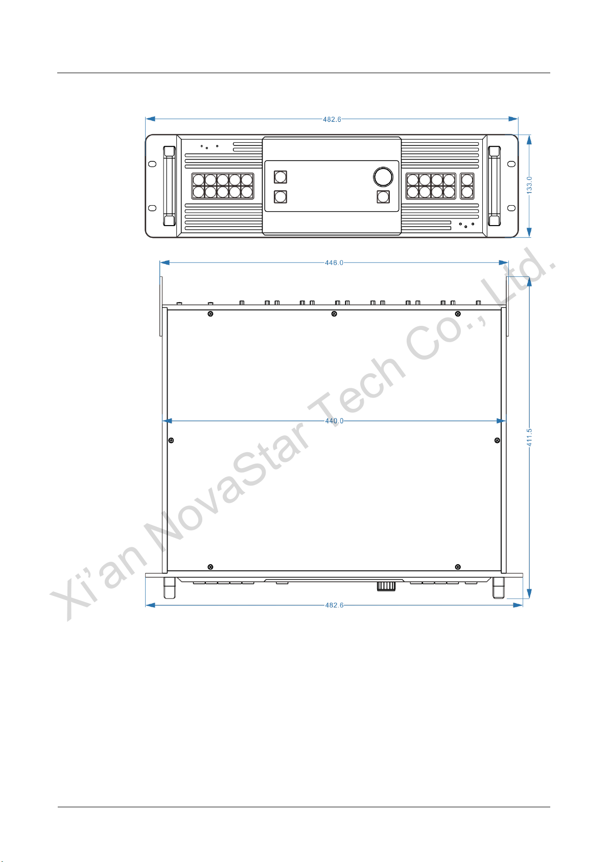
2.3 Dimensions.............................................................................................................................................. 6
3 Applications ...................................................................................................................................7
4 Operations ......................................................................................................................................9
4.1 Operation Instructions ............................................................................................................................. 9
4.2 Home Screen........................................................................................................................................... 9
4.3 Input Settings..........................................................................................................................................11
4.3.1 Dual Link ......................................................................................................................................11
4.3.2 Standard EDID.............................................................................................................................11
4.3.3 Custom EDID .............................................................................................................................. 12
4.3.4 Input Color................................................................................................................................... 12
4.4 Output Settings...................................................................................................................................... 13
4.4.1 Output Mode................................................................................................................................ 13
4.4.2 Output Resolution........................................................................................................................ 13
4.4.3 Easy Mosaic................................................................................................................................ 14
4.4.4 Advanced Mosaic ........................................................................................................................ 14
4.4.5 Output Color................................................................................................................................ 15
4.5 Layer Settings........................................................................................................................................ 15
4.5.1 Layer............................................................................................................................................ 15
4.5.2 BKG............................................................................................................................................. 18
4.5.3 Layer Copy.................................................................................................................................. 20
4.6 Display Control...................................................................................................................................... 21
4.7 Test Pattern............................................................................................................................................ 21
4.8 Preset Settings...................................................................................................................................... 22
4.9 Advanced Settings................................................................................................................................. 22
4.9.1 Synchronization........................................................................................................................... 23
4.9.2 AUX ............................................................................................................................................. 23
4.9.3 PGM Edit..................................................................................................................................... 23
Xi’an NovaStar Tech Co., Ltd.

N9
User Manual
Contents
www.novastar.tech
iii
4.9.4 Fn ................................................................................................................................................ 24
4.9.5 Return to Home........................................................................................................................... 24
4.9.6 Factory Reset.............................................................................................................................. 24
4.9.7 HDCP Function............................................................................................................................ 24
4.9.8 Technical Support........................................................................................................................ 25
4.10 Communication Settings...................................................................................................................... 25
4.11 Language............................................................................................................................................. 25
5 V-Can Control..............................................................................................................................26
6 C1 Control.....................................................................................................................................27
7 Specifications...............................................................................................................................30
Xi’an NovaStar Tech Co., Ltd.

N9
User Manual
1 Overview
www.novastar.tech
1
1 Overview
1.1 Introduction
The N9 is a high-performance seamless switcher that integrates video processing,
screen mosaic, transition effects and multi-screen display capabilities. With powerful
video signal receiving and processing abilities, the N9 supports up to 4K×2K@60Hz
video input. Using high-performance video processing technologies, it is capable of
processing and outputting ultra-high quality images. The N9 supports 9 video inputs,
7 layers and up to 4 group of DVI connectors for mosaic output. Asingle N9 unit can
load an up to 8KK screen, and multiple N9 units can be cascaded for output.
The N9 can work with NovaStar's C1 event controller and brand-new V-Can smart
control software, to realize richer screen mosaic effects and easier operation.
Thanks to the powerful capabilities of receiving and processing a variety of video
signals, the N9 can be widely used in various scenarios, such as intermediate and
high-end rental, stage control, media centers, big conference sites, exhibition sites
and concert control centers.
1.2 Features
Compatible with industry-standard video input connectors in the market
−DP 1.2 connector: 4K×2K@60Hz
−DP 1.1 connector: 4K×2K@30Hz
−HDMI 1.3 connector: 1920×1080@60Hz
−DVI connector: 1920×1080@60Hz
−3G-SDI connector: 1920×1080@60Hz
−HDMI 1.4 connector: 4K×2K@30Hz
−Dual-Link DVI connector: 4K×2K@30Hz
−VGA connector: 1920×1080@60Hz
4 groups (2 connectors in each group) of DVI connectors for mosaic output
Each group includes a main connector and a backup connector. Amaximum of 4
connectors can be used for mosaic output. The mosaic layout can be 4×1, 1×4
or 2×2. The maximum loading capacity can reach 8,800,000 pixels and the
maximum mosaic width can be up to 8192 pixels.
Xi’an NovaStar Tech Co., Ltd.

N9
User Manual
1 Overview
www.novastar.tech
2
Supports 4 single-link connectors or 2 dual-link connectors for mosaic output.
Multiple layer display
−Up to 7 layers supported at the same time. Max. resolution of each layer
can be up to 4K×2K. Cross connector output is supported.
−Layer cloning, layer mirroring and Z-order layer sorting are supported.
Customized BKG settings
You can load an image file from the control computer or C1 event controller, or
you can also capture an input source image displayed on the screen as the BKG
image.
Input source cropping supported
Easy mosaic and custom mosaic
EDID management supported
Supports input resolution management for DVI, HDMI and DP connectors.
Display control and transition effects
−Allows you to black out or freeze the screen by simply clicking one button.
−Supports setting of transition effect and effect duration.
−HDMI connector for output monitoring
−Supports monitoring of all input sources, PVW and PGM.
−Supports displaying of input resolution and frame rate.
2 ×Aux output
32 ×preset
A total of 32 user presets can be created and saved as templates which can be
used directly and conveniently.
Multiple operation modes
You can operate the N9 via its front panel, the V-Can smart control software or
C1 event controller.
Visualized color LCD screen and distinct button indicators on front panel,
simplifying system control operations
Genlock synchronization or synchronization with any input source, achieving
output vertical synchronization
Xi’an NovaStar Tech Co., Ltd.

N9
User Manual
2 Appearance
www.novastar.tech
3
2 Appearance
2.1 Front Panel
No.
Button
Function
Input source
buttons
Indicate input source status.
On: The input source is accessed but not in use.
Dim: The input source is accessed and in normal use.
Off: The input source is not accessed or abnormal.
LCD screen
Display the current device status and settings menu.
Knob
On the home screen, press the knob to enter the operation
menu screen.
On the operation menu screen, rotate the knob to select a
menu item, and press the knob to confirm the selection or
enter the submenu.
When a menu item with parameters is selected, you can
rotate the knob to adjust the parameters. Please note that
after adjustment, you need to press the knob again to
confirm the adjustment.
BACK button
Press the button to exit the current menu or cancel the
operation.
TAKE button
Send PVW to PGM.
Xi’an NovaStar Tech Co., Ltd.

N9
User Manual
2 Appearance
www.novastar.tech
4
No.
Button
Function
TEST button
Enter the test patterns menu.
Layer
buttons
Press a layer button to open the corresponding layer and
enter the layer settings menu
On: Layer is open.
Flashing: Settings menu of the corresponding layer is
opened and being edited.
Off: Layer is closed.
On the home screen, hold down a layer button to close the
layer.
BKG: Open or close the BKG.
Preset
button
Press it to enter the preset menu. A total of 32 presets can
be loaded, saved and cleared, etc.
Fn button
A custom function button
2.2 Rear Panel
Input
INPUT-1
DP 1.1 connector
Supports 3840×2160@30Hz video source input
(downward compatible) and custom resolutions.
INPUT-2
HDMI 1.3 connectors
Support 1920×1080@60Hz video source input, any input
resolution that conforms to VESA standard and custom
resolutions.
INPUT-3
INPUT-4
DVI connectors
Supports 1920×1080@60Hz video source input
(downward compatible), any input resolution that
conforms to VESA standard and custom resolutions.
INPUT-5
INPUT-6
Xi’an NovaStar Tech Co., Ltd.

N9
User Manual
2 Appearance
www.novastar.tech
5
INPUT-7
INPUT-8
DP 1.2 connector
Supports 3840×2160@30Hz video source input
(downward compatible) and custom resolutions.
INPUT-9
3G-SDI connector
Supports 1920×1080@60Hz video source input
(downward compatible).
Supports de-interlacing processing.
SDI LOOP for SDI signal loop output
Output
HDMI
HDMI output connector, capable of monitoring 9 input
sources, PVW and PGM
DVI1-DL/PGM1
DVI 1 output
If the output mode is set to dual link, this connector is
DuallinkOut1.
DVI2/PGM2
DVI 2 output
If the output mode is set to dual link, this connector is
invalid.
DVI3-DL/PVW1
DVI 3 output
If the output mode is set to dual link, this connector is
DuallinkOut2.
DVI4/PVW2
DVI 4 output
If the output mode is set to dual link, this connector is
invalid.
HDMI1/HDMI2
2 Aux output connectors
Control
ETHERNET (RJ45)
A control connector
USB (Type-B)
For the connection with control computer
USB (Type-A)
For cascading N9 units
IN–Genlock–LOOP
For synchronizing cascaded devices
OPT OUTPUT
4 optical fiber connectors for controlling the VE7 video
input expander
Power
AC100V-240V~ 50/60Hz
AC power connector
Xi’an NovaStar Tech Co., Ltd.

N9
User Manual
2 Appearance
www.novastar.tech
6
2.3 Dimensions
Unit: mm
Xi’an NovaStar Tech Co., Ltd.

N9
User Manual
3 Applications
www.novastar.tech
7
3 Applications
N9 works independently
Xi’an NovaStar Tech Co., Ltd.

N9
User Manual
3 Applications
www.novastar.tech
8
N9 works with V-Can/C1/VE7
Xi’an NovaStar Tech Co., Ltd.

N9
User Manual
4 Operations
www.novastar.tech
9
4 Operations
4.1 Operation Instructions
Knob
On the home screen, press the knob to enter the operation menu screen.
On the operation menu screen, rotate the knob to select a menu item, and press
the knob to confirm the selection or enter the submenu.
When a menu item with parameters is selected, rotate the knob to adjust the
parameters. Please note that after adjustment, you need to press the knob again
to confirm the adjustment.
ESC
Press the button to exit the current menu or cancel the operation.
Lock/Unlock
Hold down the knob and ESC button simultaneously to lock or unlock the buttons.
4.2 Home Screen
After the device is powered on, the home screen is shown as below.
Figure 4-1 Home screen
User interface description:
Area
Icon
Description
N9
-
Device name
Xi’an NovaStar Tech Co., Ltd.

N9
User Manual
4 Operations
www.novastar.tech
10
Area
Icon
Description
Lock or
unlock
Denotes the lock/unlock status of front panel
buttons.
When the N9 is connected to the C1 or V-Can, the
front panel buttons are locked.
Hold down the knob and ESC button to manually
lock or unlock the front panel buttons.
IP address
192.168.0.10
Device IP address
Layer
/
Layer status
Highlighted: Layer enabled
1: Layer number
1-DP1.1: Layer input source
RES
1920×1080@60Hz
Output resolution
Screen
1920×1080
Output screen size and mosaic layout
AUX
/
Highlighted: AUX enabled and AUX input source
displayed
Gray: AUX disabled
Ex: MVR/AUX output function of the VE7
−MVR: MVR/AUX connector of the VE7 used for
monitoring
−VE7 input source name: MVR/AUX connector of
the VE7 used for loop output
OPT
/
Optical fiber port status
Highlighted: The optical fiber port connected to the
VE7
Gray: The optical fiber port not connected to the
VE7
N9
connection
The device connected to the control PC via USB
The device connected to the control PC via Ethernet
port
The device not connected to the control PC
BKG
BKG enabled
BKG disabled
Output
display
Test pattern
FTB
Freeze
Normal
PGM edit
PGM edit enabled
PGM edit disabled
Xi’an NovaStar Tech Co., Ltd.

N9
User Manual
4 Operations
www.novastar.tech
11
Area
Icon
Description
Genlock
Genlock enabled and locked
Genlock abnormal
Genlock disabled
4.3 Input Settings
On the home screen, press the knob to enter the operation menu screen. Rotate the
knob to select Input Settings, and then press the knob to enter the submenu.
Figure 4-2 Input settings
4.3.1 Dual Link
When the input source is from the VE7, dual link mode can be set.
Step 1 On the input settings screen, rotate the knob to select an input source with an Ex in
front of it.
Step 2 Press the knob to enter the input source settings screen.
Step 3 Dual Link is selected by default. Press the knob to confirm the selection.
Figure 4-3 Dual link
4.3.2 Standard EDID
The N9 and VE7 allow for standard input resolution settings.
Step 1 On the Input Settings screen, rotate the knob to select an input source and press
the knob to enter the input source settings screen.
Step 2 Rotate the knob to select Standard EDID and press the knob to enter the standard
EDID settings screen.
Xi’an NovaStar Tech Co., Ltd.

N9
User Manual
4 Operations
www.novastar.tech
12
Step 3 Rotate the knob to set Resolution and Frame Rate.
Step 4 Rotate the knob to select Apply and press the knob to confirm the settings.
Figure 4-4 Standard input EDID settings
Note:
For different input sources, the supported EDIDs are different.
If a custom EDID is required, you can set it on the control PC or C1 event controller.
When the input source is SDI, setting EDID is not supported.
4.3.3 Custom EDID
Step 1 On the Input Settings screen, rotate the knob to select an input source and press
the knob to enter the input source settings screen.
Step 2 Rotate the knob to select Custom EDID and press the knob to enter the custom
EDID settings screen.
Step 3 Rotate the knob to set Width, Height and Frame Rate.
Step 4 Rotate the knob to select Apply and press the knob to confirm the settings.
Figure 4-5 Custom EDID
4.3.4 Input Color
Step 1 Rotate the knob to select Input Settings, and then press the knob to enter the input
source settings screen.
Step 2 On the Input Settings screen, rotate the knob to select an input source.
Step 3 Press the knob to enter the input source settings screen.
Step 4 Rotate the knob to select Input Color and press the knob to enter the input color
settings screen.
Step 5 Rotate the knob to adjust the input color parameters and press the knob to confirm
the settings.
For the detailed input color parameter settings, please refer to Table 4-1.
Xi’an NovaStar Tech Co., Ltd.

N9
User Manual
4 Operations
www.novastar.tech
13
Figure 4-6 Input color settings
Table 4-1 Input color parameter settings
Name
Value
Range
Default
Value
Description
Brightness
0–100
50
Adjust the screen brightness. The larger this
value is, the brighter the screen will be.
Contrast
0–100
50
Adjust the difference between the darkest and
brightest areas of the image displayed on the
screen. The larger this value is, the bigger this
difference will be.
Saturation
0–100
50
Adjust the purity or vividness grade of the image
color. The larger this value is, the purer the
color will be.
Hue
-180–180
0
Adjust the gradation or variety of the image
color. The larger this value is, the intenser the
color will be.
Reset
Reset all the input color parameters to defaults.
4.4 Output Settings
4.4.1 Output Mode
The N9 supports both single link and dual link output modes. When it is set to single
link mode, DVI1, DVI2, DVI3 and DVI4 are used as single link connectors for mosaic
output. When it is set to dual link mode, DVI1 and DVI3 are used for output, while
DVI2 and DVI4 are unavailable.
On the main menu screen, rotate the knob to choose Output Settings > Output
Mode, and then rotate the knob again to select Single Link or Dual Link.
Figure 4-7 Output mode settings
4.4.2 Output Resolution
Set the resolution of the output connector. The N9 supports standard and custom
resolution settings. When the resolution is set, the resolutions of all output connectors
for mosaic output are the same.
Standard Resolution
Xi’an NovaStar Tech Co., Ltd.

N9
User Manual
4 Operations
www.novastar.tech
14
On the main menu screen, rotate the knob to choose Output Settings > Output
Resolution > Standard Resolution to enter the standard resolution settings
screen. Then rotate the knob again to set Resolution and Frame rate, and
press the knob to confirm the settings.
Figure 4-8 Output resolution - standard
Custom Resolution
On the main menu screen, rotate the knob to choose Output Settings > Output
Resolution > Custom Resolution to enter the custom resolution settings
screen. Then rotate the knob again to set Width, Height and Frame rate, and
press the knob to confirm the settings.
Figure 4-9 Output resolution - custom
When you have completed the output resolution settings, rotate the knob to select
Apply and press it to make the settings take effect.
4.4.3 Easy Mosaic
The N9 provides 8 DVI output connectors (4 main and 4 backup). It supports both
single DVI connector output and multiple DVI connectors mosaic output.
You can set Total Width and Total Height based on the screen size, then the N9 will
automatically calculate the width and height of each output connector and provide
you a mosaic layout.
Figure 4-10 Easy mosaic
4.4.4 Advanced Mosaic
The supported mosaic layouts including 1×1, 1×2, 1×3, 1×4, 2×1, 3×1, 4×1 and 2×2.
You can select different layouts based on the screen structure and resolution.
Step 1 On the main menu screen, rotate the knob to choose Output Settings > Advanced
Mosaic > Layout to enter the advanced mosaic screen.
Step 2 Press the knob to enter the mosaic layout screen. Then rotate the knob to select the
desired layout and press the knob to confirm the selection.
Step 3 Rotate the knob to select Connector and press the knob to confirm the selection.
Xi’an NovaStar Tech Co., Ltd.

N9
User Manual
4 Operations
www.novastar.tech
15
Step 4 Rotate the knob to set Width and Height for the selected output connector.
Step 5 Rotate the knob to select Apply and press the knob to confirm the settings.
Figure 4-11 Advanced mosaic
4.4.5 Output Color
The N9 supports output color settings. When you adjust the output color parameters,
the settings will take effect in real time.
Figure 4-12 Output color
4.5 Layer Settings
The N9 supports at most 7 layers. Each layer supports cross connector output, BKG
settings and layer cloning.
4.5.1 Layer
On the main menu screen, rotate the knob to choose Layer Settings > Layer and
press the knob to enter the layer settings screen.
Figure 4-13 Layer settings
Layer: Select a layer.
Layer is selected by default. Press the knob and rotate it to select a layer.
Status: Set to open or close the layer. The options are On and Off.
Rotate the knob to select Layer Status, and press the knob and rotate it again
to select On to enable the selected layer.
Input Source: Select the input source for the layer. Only when the layer status is
set to On, this menu item is available.
Rotate the knob to select Input Source, and press the knob the rotate it again to
select an input source for the selected layer.
Xi’an NovaStar Tech Co., Ltd.

N9
User Manual
4 Operations
www.novastar.tech
16
Layer Size: Set the width, height and position of the selected layer. Only when
the layer status is set to On, this menu item is available.
Rotate the knob to select Layer Size, and press the knob to enter the layer size
settings screen. You can set H Width, V Height,Initial X and Initial Y of the
layer.
Input Crop: Crop the input source image of the layer and then make the
cropped part full screen. Only when the layer status is set to On, this menu item
is available.
Rotate the knob to select Input Crop, and press the knob to enter the input crop
settings screen. You can set the input crop status as On or Off, and set H
Width, V Height,Initial X and Initial Y of the cropped part.
Layer Color: Set the color of the output image.
Selecting Layer
Layer lists the names of layers (Layer 1–Layer 7). You can select one layer each
time from the list.
Figure 4-14 Selecting layer
1. Rotate the knob to select Layer.
2. Press the knob to enter the layer selecting screen.
3. Rotate the knob to select a layer and press it to confirm the selection.
Layer Status
Set the layer status as On or Off. When the status is On, the layer is visible. When
the status is Off, the layer is invisible.
Input Source
Set or change the input source for the selected layer. When the N9 works with the
VE7, the input source with an Ex in front of it is the input source of the VE7.
Layer Size
Set the size and position of the selected layer.
Figure 4-15 Setting layer size
H Width: Set the horizontal width of the layer. The default value is the half of the
input source width.
V Height: Set the vertical height of the layer. The default value is the half of the
input source height.
Xi’an NovaStar Tech Co., Ltd.
Other manuals for N9
2
Table of contents
Other NovaStar Switch manuals