Novasub SCU-2DRVL User manual

Seascape BV
De Hoogjens 22
4254 XW Sleeuwijk
The Netherlands
Phone: +31-183-307900
Email: info@novasub.com
www.novasub.com
www.seascape.nl
SCU-2DRVL Manual
Version: 1.32 Preliminary
Operations Manual
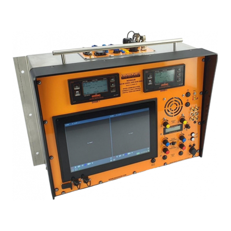
SCU-2DRVL – 2 Diver radio with camera & light
control.
NOVASUB Surface control unit two diver radio with
integrated camera and light control.

Version: 1.35
SCU-2DRVL MANUAL
1 of 27
Index
1 HELP & SUPPORT ..............................................................................................................................................................................4
2 SAFETY MEASUREMENTS..................................................................................................................................................................5
SAFETY PRECAUTIONS............................................................................................................................................................................. 5
3 INSTALLATION ..................................................................................................................................................................................6
4 MAINTENANCE .................................................................................................................................................................................6
4.1.1 Maintenance by authorized dealer or distributor ........................................................................................................................ 6
MAINTENANCE SCHEME.......................................................................................................................................................................... 6
5 WARRANTY ......................................................................................................................................................................................7
WARRANTY PERIOD............................................................................................................................................................................... 7
EXCLUSIONS AND LIMITATIONS ................................................................................................................................................................ 7
THIS LIMITED WARRANTY IS NOT ENFORCEABLE IF ITEM: ............................................................................................................................... 7
LIMITATION OF LIABILITY......................................................................................................................................................................... 7
6 GLOSSARY.........................................................................................................................................................................................8
7 GENERAL SPECIFICATIONS ................................................................................................................................................................8
8 OPTIONAL.........................................................................................................................................................................................9
BOBOX .............................................................................................................................................................................................. 9
SENSOR DATA INPUT ON VIDEO OVERLAY ................................................................................................................................................. 11
8.2.1 UDS-1 Underwater Depth sensor ............................................................................................................................................... 11
8.2.2 UDS-3 Underwater Depth sensor ............................................................................................................................................... 11
THICKNESS GAUGE (T) ......................................................................................................................................................................... 11
CP PROBE (CP)................................................................................................................................................................................... 11
THIRD PARTY CAMERA CONNECTION........................................................................................................................................................ 11
LOW VOLTAGE POWER SUPPLY ............................................................................................................................................................... 11
9 GENERAL FUNCTIONS & CONNECTIONS..........................................................................................................................................12
MAIN POWER..................................................................................................................................................................................... 13
DIVER COMMUNICATIONS..................................................................................................................................................................... 14
9.2.1 2 wire comms configuration ...................................................................................................................................................... 14
9.2.2 4 wire comms configuration ...................................................................................................................................................... 14
9.2.3 Comms Mode ............................................................................................................................................................................. 14
9.2.4 2/4S - 2 wire simplex .................................................................................................................................................................. 14
9.2.5 4HD – 4 wire Half Duplex ........................................................................................................................................................... 14
9.2.6 4FD- 4 wire Full Duplex .............................................................................................................................................................. 14
9.2.7 Comms Volume control.............................................................................................................................................................. 15
9.2.8 Internal MIC ............................................................................................................................................................................... 15
9.2.9 Push To Talk (PTT) ...................................................................................................................................................................... 15
9.2.10 Cross-Talk .............................................................................................................................................................................. 15
INTERNAL SPEAKER .............................................................................................................................................................................. 15
EXTERNAL SPEAKER ............................................................................................................................................................................. 15
HEADSET / MIC .................................................................................................................................................................................. 16
CAMERA &LIGHT ................................................................................................................................................................................ 16
SENSOR DATA IN(OPTIONAL) .............................................................................................................................................................. 16
DATA CONTROL (NOVANET) ................................................................................................................................................................. 17
9.8.1 Data Control............................................................................................................................................................................... 17
9.8.1.1 novaNET systems .................................................................................................................................................................................. 17
9.8.1.2 How it works ......................................................................................................................................................................................... 17
10 MAIN OPERATING ..........................................................................................................................................................................18
SYSTEM STARTUP ................................................................................................................................................................................ 18
CAMERA AND LIGHT CONTROL................................................................................................................................................................ 19
10.2.1 Camera signal ........................................................................................................................................................................ 19
10.2.1.1 Why use video transmission over Twisted pair..................................................................................................................................... 19
10.2.2 Light controller ...................................................................................................................................................................... 19

Version: 1.35
SCU-2DRVL MANUAL
2 of 27
11 PANEL CONNECTIONS.....................................................................................................................................................................20
MIC/HEADSET.................................................................................................................................................................................... 20
12 BACK CONNECTIONS.......................................................................................................................................................................21
POWER SUPPLY................................................................................................................................................................................... 21
MAIN CABLE CONNECTION .................................................................................................................................................................... 22
12.2.1 Standard connector, SCU-02-15a and SCU-02-15b................................................................................................................ 22
12.2.2 Connector with sensor data, SCU-02-16a and SCU-02-16b ................................................................................................... 22
12.2.1 Comms Banana sockets ......................................................................................................................................................... 23
12.2.2 Ext. Speakers.......................................................................................................................................................................... 23
12.2.3 Audio Out............................................................................................................................................................................... 23
12.2.4 Video Out............................................................................................................................................................................... 23
12.2.5 Audio Out All.......................................................................................................................................................................... 23
12.2.6 Audio In.................................................................................................................................................................................. 23
12.2.7 Data Control (novaNET)......................................................................................................................................................... 24
12.2.7.1 How it works ......................................................................................................................................................................................... 24
OPTIONAL EXTRA CONNECTORS.............................................................................................................................................................. 24
12.3.1 Data In connection RS232, SCU-02-49................................................................................................................................... 24
12.3.2 Data In/Out connection to DDG, SCU-02-50.......................................................................................................................... 25
12.3.2.1 UDS-3 connected to SCC ....................................................................................................................................................................... 25
12.3.2.2 UDS-3 connected to DDG ...................................................................................................................................................................... 25
12.3.3 DATA Out/In to DDG, SCU-03-11 ........................................................................................................................................... 25
12.3.4 BoBox..................................................................................................................................................................................... 26

Version: 1.35
SCU-2DRVL MANUAL
3 of 27
WARNING
YOU MUST READ the SCU-2DRVL manual before using the SCU-2DRVL. Failure to do so may
lead to improper use, serious injury or death. Care should be taken to follow the instructions
correctly and also conduct a separate risk assessment prior to commencing work
WARNING
Is used in connection with a procedure or situation that may result in serious
injury or death.
CAUTION
Is used in connection with a procedure or situation that will result in damage
to the product.
NOTE!
Is used to emphasize important information.
Disposal of the device
Please dispose of the device in an appropriate way, treating it as electronic waste. Do not throw it in the garbage. If
you wish, you may return the device to your nearest Novasub dealer.

Version: 1.35
SCU-2DRVL MANUAL
4 of 27
1 Help & Support
First please read this manual thoroughly. Further details about a Warranty Statement can be found at the chapter 5 -
Warranty.
For technical support contact your local a Novasub Authorized Service Center or Seascape BV.
Seascape BV
De Hoogjens 22
NL-4254 XW Sleeuwijk
The Netherlands
T. +31-183-307900
F. +31-183-307910
E. info@seascape.nl
www.seascape.nl
Copyright © Seascape BV
All Rights reserved.
If you have cause to use our technical support service, please make ensure that you have the following details at hand prior to
calling:
•system serial number
•firmware version and build number
•fault description
•any remedial action implemented

Version: 1.35
SCU-2DRVL MANUAL
5 of 27
2 Safety measurements
The content of this manual may be changed without prior notices. Seascape cannot under any circumstances be held liable for
any special, indirect or incidental damages in connection with, or as a result of the purchase or use of this product and items
that come.
Safety precautions
Do not attempt to use the SCU-2DRVL without reading this instruction manual in its entirety, including all the warnings. Make sure that
you fully understand the use, displays and limitations of the instrument. If you have any questions about the manual or the SCU-2DRVL,
contact your Novasub Authorized Service Center before using the SCU-2DRVL.
Always remember that YOU ARE RESPONSIBLE FOR YOUR OWN SAFETY!

Version: 1.35
SCU-2DRVL MANUAL
6 of 27
3 Installation
The Novasub SCU units are standard 19” rack mountable. The SCU-2DRVL can be fitted to the 19” rails with adequate
screws. We advise to use plastic washer between the screw head and the panel. This avoids damaging the panel and
losing the screw do to vibration.
WARNING
Make sure there is enough forced or natural ventilation available around the SCU unit
Do not cover the top and bottom of the SCU, the top and bottom are open for ventilation
Avoid any moisture onto the SCU
4 Maintenance
The SCU-2DRVL is a 19” rack case. You must treat it with the same proper care and caution as any other electronic instrument.
4.1.1 Maintenance by authorized dealer or distributor
Have your SCU-2DRVL serviced by a Novasub Authorized Service Center. This service will include a general operational check,
replacement of the battery, and overall upgrade of firmware. The service requires special tools and training.
Maintenance scheme
By Customer
Charging battery
Regularly
By Novasub Authorized Service Center
Servicing SCU-2DRVL
2 years
Internal backup battery replacement
2 Yearly
WARNING
•It is not allowed to disassemble the SCU-2DRVL or to repair the product by unqualified personal or disassemble part,
in that case all warranties are void.
•The SCU-2DRVL is not waterproof, avoid contact with any water or moisture.
• DO NOT use the SCU-2DRVL if you detect any moisture or water inside.
CAUTION
• Protect the unit from shock, extreme heat, direct sunlight, and chemical attack.
• The SCU-2DRVL cannot withstand the impact of heavy objects like air cylinders, nor chemicals like gasoline, cleaning solvents,
aerosol sprays, adhesive agents, paint, acetone, alcohol, etc. Chemical reactions with such agents will damage the seals, case
and finish.
• Do not use compressed air to blow water off the unit.

Version: 1.35
SCU-2DRVL MANUAL
7 of 27
5Warranty
Novasub warrants that during the Warranty Period Novasub or a Novasub Authorized Service Center (hereinafter Service Center) will, at
its sole discretion, remedy defects in materials or workmanship free of charge either by a) repairing, or b) replacing, or c) refunding,
subject to the terms and conditions of this Limited Warranty. This Limited Warranty is only valid and enforceable in the country of
purchase, unless local law stipulates otherwise.
Warranty Period
The Limited Warranty Period starts at the date of original retail purchase. The Warranty Period is two (2) years for the SCU-2DRVL.
Warranty applies only on manufacturing defaults. The Warranty Period is one (1) year for accessories, including mounting hardware and
connector cables.
Exclusions and Limitations
This Limited Warranty does not cover:
1. a) normal wear and tear;
b) defects caused by rough handling or;
c) defects or damage caused by misuse contrary to intended or recommended use;
2. user manuals or any third-party items;
3. defects or alleged defects caused by the use with any product, accessory, software and/or service not manufactured or supplied
by Novasub;
4. battery (only first 6 month after purchase is under warranty).
This Limited Warranty is not enforceable if item:
1. has been opened beyond intended use;
2. has been repaired using unauthorized spare parts; modified or repaired by unauthorized Service Center;
3. serial number has been removed, altered or made illegible in any way, as determined at the sole discretion of Novasub;
4. has been exposed to chemicals or excessive water spraying. Novasub does not warrant that the operation of the product will be
uninterrupted or error free, or that the product will work with any hardware or software provided by a third party.
Limitation of Liability
To the maximum extent permitted by applicable mandatory laws, this Limited Warranty is your sole and exclusive remedy and is in lieu of
all other warranties, expressed or implied. Novasub shall not be liable for special, incidental, punitive or consequential damages,
including but not limited to loss of anticipated benefits, loss of data, loss of use, cost of capital, cost of any substitute equipment or
facilities, claims of third parties, damage to property resulting from the purchase or use of the item or arising from breach of the
warranty, breach of contract, negligence, strict tort, or any legal or equitable theory, even if Novasub knew of the likelihood of such
damages. Novasub shall not be liable for delay in rendering warranty service.

Version: 1.35
SCU-2DRVL MANUAL
8 of 27
6 Glossary
The Novasub diver communication radio is based on the latest electronic technology and is specially designed for an
outstanding diver and surface sound quality. The unit is standard fitted for a 2 diver connection and has a built in LED light and
video transmission over twisted pair or coax controller for camera and light.
The video controller is auto tunable for any cable up to 600 m. The unit has a mains and battery backup. Is powered with a
built in smart battery charger and has a battery state condition monitoring. Standard the radio is fitted with a volume
controllable external speaker amplifier. Both diver’s and tender voice are heard on the external speaker.
The SCU-2DRVL series have the latest audio electronics for superior audio both at the diver and tender end. The built in
Microphone makes it able to have a crystal clear audio at the diver end. The system works both with 2 and 4 wire. In 4 wire
comms you can also select full duplex comms, no PTT pressing is needed. In 4 wire mode the divers can speak to each other
while the Tender can listen in. The Tender can speak to the divers’s by pressing the PTT. In 4FD mode the tender does not
have to press any PTT and can speak and listen to the both divers. Just like a normal telephone conversation.
*works only with 4 wire comms
The unit also has a NovaBUS (rs485) connection to interface with other Novasub systems, like the SCU-DVR2 or DDG. The
Novabus makes it possible to share data and control camera and light from the SCU-DVR2 recorders or NSDVRsoft, video
recording&control software
7 General Specifications
Specifications
Ext. Power
supply
:
100-240 VAC, 50/60 Hz 100 watt
Battery life
:
10 hours -> 2 diver comms only
0.5 hours -> 2 Divers Camera&light
1 hours ->1 Diver Camera&light
Light control
(Only L and VL
versions)
:
0-100 % dimmable light control for the
Novasub Lux3R or 6R and up to 25 watt
halogen 12v lights
Int. Power supply
:
24 vdc rechargeable battery with
battery status indication, UPS
function
Video out
:
2x per diver, 1Vpp/75 Ohm
Audio Out
:
2x per diver, signal of 1Vpp
Diver volume
control
:
Potentiometer control
Tender volume
control
:
Potentiometer control
Video control
(Only VL
version)
:
Video transmission over twisted pair or
coax, auto-tune to 600 m, 32 vdc
(12,15,24 vdc optional)
External Speaker
:
Amplifier 10W/4-8 Ohm with volume
control
Communication
:
2 wire - simplex, 4 wire - full duplex
Dimensions
:
19” 3U high – 350 mm deep
(excluding connectors)
Diver to diver
:
Cross-talk switch, full duplex (4 wire)
:
Connections
Audio out
:
2x RCA (Cinch)
Video out
:
2x BNC
Audio out All
:
1x RCA (Cinch)
Audio in
:
1x RCA (Cinch)
Headset/Mic
:
Bulgin 8pin, audio out, Mic in, PTT
Ext. speaker
:
2x Banana screw sockets
Umbilical
connector
:
2x Multi pin circular connector, comms,
camera and light
Diver comms
:
2x2 Banana sockets (Parallel with
Multi-pin) (Mic, Head diver)
Bobox (optional)
:
Bulgin, 8 pin
DATA
:
Bulgin, 8 pin
Power in
:
IEC C14 mates with C13
novaNET
:
Screw terminal
Features
2 and 4 wire communication
Automatic battery charger and conditioner
Camera & light control
High Power Audio
Multi-pin & Banana socket connections
External speaker amplifier

Version: 1.35
SCU-2DRVL MANUAL
9 of 27
8 Optional
Diver depth to overlay ; direct connection of UDS-3 depth sensor data to video overlay.
DDG diver data to overlay ; DDG depth and dive/time data to video overlay.
BoBox ; Breakout Box for remote comms control with both divers, 50 m cable.
Thickness Gauge to overlay ; Tritex or Cygnus Thickness data to video overlay.
Analog value to overlay ; any 0-10v or 4-20 ma signal data to video overlay.
Digital data to overlay; rs 232 and rs422/485 data input to video overlay.
Remote control software ; Novasub DVR software to remote control and view the SCU-2DRVL G3.
Table Mic1 & 2
Noise cancelation headset
12-24 Vdc power supply connection
BOBOX
The Bobox can be ordered at new order or post ordered for
integration on previously built systems.
The Bobox is an optional Break Out Box to use as an remote
extension for 2 diver communication. The Bobox is standard
supplied with 30 m cable. The Bobox has a built in amplifier
and speaker. Also PTT for each diver and volume control of
the speaker and divers.
Also an external Headset/Mic can be connected.
All Tender-Diver and Diver communication are heared on the
Bobox as well as the SCC.
Also the SCC controls are fully functional.
Application:
Remote setup out of the diver container at the diver
launching platform
Remote setup in a control room for any machinery
Remote setup in a client area
The Bobox is connected to an optional connector installed on
the SCC.
TMic 1&2
There are 2 versions of table microphones available for the SCC-2DR comms radio.
8.2.1 Tmic1
Table Microphone with PTT switch for connection the the standard Head/Mic
connector of the SCC-2DVRL-DVR.
8.2.2 Tmic2
Table Micrphone with 2x PTT, for each diver
one. With microphone volume control.
Requires BoBox connection on the SCC-
2DR.
NSBCB camera
LUXR 3&6 Led lights
BoBox

Version: 1.35
SCU-2DRVL MANUAL
10 of 27
NSHEADset1, Noise Cancellation Headset
Novasub rugged noise cancelling Headset with Mic and PTT for Novasub
Diver radio’s.
The NSHEADset1 is ideal for use in noise surroundings to be able to hear
and speak clearly with the diver.
It has a build on PTT switch.
It connects directly to the standard Head/Mic connector of the SCC-2DR.
Low voltage power supply
The SCC can also be fitted with an extra external power supply connection of
12-36 vdc.
The SCC can then be powered with 110 /230 vac or 12-36 vdc.

Version: 1.35
SCU-2DRVL MANUAL
11 of 27
Sensor data input on Video overlay
The SCU-2DRVL can be supplied with a DSI data to video text&data overlay. The DSI enables the input of different
analog and digital sensors which can be displayed on the monitor video overlay. The Data can be 0-10v, 4-20 ma, rs232
and rs422/485. And the standard Novasub UDS-3 depth sensor can be interfaced also to the DSI.
8.5.1 UDS-1 Underwater Depth sensor
The USD-1 depth sensor is an analog pressure sensor in a
underwater housing with a 3 pin connector. The sensor outputs a
4-20 ma signal through the diver umbilical/cable to the SCC’s
overlay. The sensors are standard 0-60 MSW and are so
calibrated together with the SCC’s overlay OSD-2 unit. Other
pressure depth ranges are possible.
8.5.2 UDS-3 Underwater Depth sensor
The UDS-3 depth sensor is an analog pressure sensor based on the
HART digital protocol data signal over 4-20 ma. The sensors transmit the
depth data digital and the sensor is internal calibrated. The calibration is
standard 0-7 Bar absolute. The OSD-2 overlay unit displays the water
depth in MSW with and accuracy of < 0,2% of the FS (60 MSW)
Thickness Gauge (T)
The data of a Ultrasoon thickness gauge can be displayed on the video
overlay. Standard the OSD-2 is configured for the Tritex Multigauge 3000.
CP probe (CP)
The OSD-2 has a built in 0-2000 mV input which can be used with a underwater Proximity Probe to measure the
cathodic potentials.
Third party camera connection
The SCU-2DRVL is fully built to accept the standard Novasub video cameras.
However any brand of analog video camera can be connected to the SCU-2DRVL.
The standard voltage output to the camera connection is 32 vdc.
This can be configured to a lower voltage by Seascape at its factory.
On new orders please specify required voltage range.
Standard range are 12 vdc, 15 vdc and 24 vdc.
Low voltage power supply
The SCC can also be fitted with an extra external power supply connection of 12-36 vdc.
The SCC can then be powered with 110 /230 vac or 12-36 vdc.

Version: 1.35
SCU-2DRVL MANUAL
12 of 27
9 General Functions & Connections
The SCU-2DRVL has the following control function and connections.
Main Power
Switch
Comms
Mode
Volume
Diver 1
Volume Tender
Cross-Talk
PTT
Speaker
Switch
Speaker
Volume
Ext.
Speaker
Mic/Headset
Lights
Dimmer
Batt. Status
LED’s
Volume
Diver 2
PTT
Cameras
Switch
Lights Switch
Audio Out
Video Out
Comms Mic
Comms
Head
Multi-pin
connector
Power supply
Ext.
Speaker
DATA in
Data control
novaNET
BoBox
Audio out
All
Audio in

Version: 1.35
SCU-2DRVL MANUAL
13 of 27
Main Power
The Main power switches on and off the complete unit.
When the external IEC plug is inserted on the top left of the case the internal battery will be automatically charged. The
system can be powered with 100 – 240 vac 50/60 Hz and requires 100 watts.
The Charge level LED’s will indicate that the system is being charged and the status of charge. Charging time for a fully
discharged system will take approx. 10 -12 hrs.
When system is fully charged the batteries are automatically trickle charged to maintain full capacity.
The Main power does not need to be switched on to the charge the system.
Charge level
BATT
PWR
Status
System On and external
powered. Battery charging;
= Full
= Half Full and charging
= Empty and charging
System On and running on
battery. Battery discharging;
= Empty
= Half Full
= Full
System Off and external
powered. Battery charging;
= Full
= Half Full and charging
= Empty and charging
LED on and Blinking
LED on and solid
LED off

Version: 1.35
SCU-2DRVL MANUAL
14 of 27
Diver Communications
The diver audio is standard set for a 2 wire communications (simplex).
The divers can only speak to each other when the surface operator pushes the cross-talk switch to the desired direction.
The SCU-2DRVL can also be set for 4 wire communication (duplex)
The divers have an open 2 way communications with each other without any selection from the surface. The surface will
hear both divers and can talk to the desired diver by pressing the corresponding PTT. Also can the comms be set for
Full duplex. The there is a full open communication (conference) between the divers and surface.
9.2.1 2 wire comms configuration
The SCU-2DRVL is standard fitted with a 10 pin multipin connector.
The audio comms for 2 wire comms is connected to the diver umbilical via the multipin
connector (pins H,J) or via the yellow Banana sockets
9.2.2 4 wire comms configuration
The SCU-2DRVL is standard fitted with a 10 pin multipin connector.
The audio comms for 4 is connected to the diver umbilical via the multipin connector (pins
H,J,G,K) or via the yellow and blue Banana sockets
9.2.3 Comms Mode
The Comms Mode is a selection comms mode switch. This allows the use of a 4 wire
comms system and still be able also to use the system as a 2 wire system.
The 4 wire configurations has 3 user modes:
2S - 2 or 4 wire simplex
4HD- 4 wire Half duplex surface to diver, full duplex diver to diver
4FD- 4 wire Full duplex, surface and divers full duplex without any PTT
9.2.4 2/4S - 2 wire simplex
This mode is the same as the standard comms when using 2 wire. This works with either 2 or 4 wires comms cable
configuration. The diver will always be heard at the surface and the Tender needs to push the PTT switch to talk to
the diver. The divers can only speak to each other when the Tender uses the Cross to Talk switch from diver 1 to
diver 2 and vice versa.
9.2.5 4HD – 4 wire Half Duplex
This mode uses a 4 wire comms cable configuration. In this mode the divers can speak with each other without any
control from the Tender. The Tender will hear both.
The Tender needs to push the PTT button to speak to the divers.
9.2.6 4FD- 4 wire Full Duplex
This mode allows to have a full open communication between divers and Tender to divers without using the PTT
buttons. Like a conference call.

Version: 1.35
SCU-2DRVL MANUAL
15 of 27
9.2.7 Comms Volume control
Each diver has a Tender and Diver volume control.
The Volume Diver is the volume control of what the diver hears
The Volume Tender is the volume control of what the tender hears
9.2.8 Internal MIC
On the panel between the Volume Tender control, the internal MIC is
positioned. It is not needed to place your mouth close the the Mic.
Normal arm length distance is sufficient to pick-up the Tender speaking
volume.
9.2.9 Push To Talk (PTT)
The button per diver to press when the Tender want’s to speak to the
diver.
9.2.10 Cross-Talk
The cross talk switch can be used to have Diver 1 speak to Diver 2 in a
2 wire comms configuration. When the toggle switch is pushed
direction Diver 2, then Diver 1 can speak to Diver 2. If the toggle switch
is pushed towards Diver 1, then Diver 2 can speak to Diver 1.
Internal Speaker
The Internal Speaker can be switched off with the rocker switch Speaker. This can be used when operating with the
Mic/Headset or only with the external speakers
External Speaker
The SCC has a built in 10 watt amplifier to which an external 4-8 ohm (10-30w) speaker can be
connected. The external speaker has its own volume control.
All conversation, divers and tender are heard on the ext. speaker.
Banana
connection or
bare wire

Version: 1.35
SCU-2DRVL MANUAL
16 of 27
Headset / Mic
The external headset/Mic connector can be used to connected the supplied headset with mic and used with the SCC built in
PTT to speak to the divers.
Another option is to us the headset/mic connector for an optional MIC with PTT to talk to the divers. The internal speaker can
be switched of if required.
When the Headset with Mic or the MIC only are connected, the internal MIC is automatically switched off.
Headset/Mic standard supplied with SCC, MIC-PTT is optional
Camera & light
The SCU-1DRVL version has a LED light controller with video camera control per diver
channel.
When Camera or light are switched on the power is enable to the camera and light.
The light can be dimmed with the Yellow turning knob.
Sensor DATA In (Optional)
The onboard camera&light controller can interface an optional PCB with input of any
type of sensor.
The type of sensor and data input can be rs232/422 or 485, 4-20 ma and 0-10v.
This data can be used to be displayed on the video text overlay of a SCU-DVR2 or the
novasub-DVR software.

Version: 1.35
SCU-2DRVL MANUAL
17 of 27
Data control (novaNET)
9.8.1 Data Control
The Data control is a rs485 2 wire BUS interface connection. All G3 Novasub SCC and SCU units are fitted with
this BUS connection which we call novaNET.
With novaNET connection between the various SCC and SCU units you can control the camera & light on/off and
dimming, and data is being sent to and from the units.
9.8.1.1 novaNET systems
Novasub has released the following units with the novaNET interface:
SCU-1DRVL
SCU-2DRVL
SCU-DVR2 (1CH,2CH &3CH)
SCU-PCDVR04
SCC-PCDVR04
DDG1
DDG2
SCU-xVL
9.8.1.2 How it works
With novaNET controls you can control cameras & lights from any SCU or SCC unit within the network. Each
camera & light is addressed with CH1 up to CH16. This is set during manufacturing. There will be always be
one unique address 1. But address 1 (CH1) with the belonging camera and light can be controlled from more
than one SCC/SCU unit. All works in parallel, with overrule from the last SCC/SCU control command send.
This means you can switch on the camera with the switch on the SCU-1DRVL and switch it off with a SCU-
DVR2. The switch on the SCU-1DRVL is still in the on position but the LED on the switch will be off. You can
switch on again with the SCU-DVR2 by pressing on CAM or with the SCU-1DRVL by toggling the switch off
and on again. The same is for the lights.
If you switch on from a SCU-DVR2 or from the NovasubDVR software, the LED in the swith will lid up, even if
the switch on the SCU-1DRVL is in off position.

Version: 1.35
SCU-2DRVL MANUAL
18 of 27
10 Main Operating
This chapter describes the main basic operations to be able to start the system and switch on camera and light (only L, VL
versions)
System startup
Connect the main cable with the camera and light, connect the power supply. Make sure that the actual camera and light
are connected at the other end of the cable.
Follow next steps to quick start the system.
Plug in Main
power cables
Plug in external power supply 100-240 vac to 24 vdc. The
system will automatically start charging the internal battery.
Even with the main power switch off.
Connect cable
Connect cable with comms, camera and light
Switch Main
power on
BATT
PWR
Status
System On and external powered.
Battery charging;
= Full
= Half Full and charging
= Empty and charging
System On and running on battery.
Battery discharging;
= Empty
= Half Full
= Full
System Off and external powered.
Battery charging;
= Full
= Half Full and charging
= Empty and charging
LED on and Blinking
LED on and solid
LED off
Battery / Power status
Comms Mode
For Simplex 2 or 4 wire comms set, the switch to 2/4S
For Duplex between divers set to 4HD
Speaker
Press the Speaker switch to the right with the 1 down. You
can now hear the diver audio on the internal speaker
Switch on the
Camera and
light
(Only L & VL)
Press the camera switch to the right, the CAM green LED
switches on.
Press the light switch to the right, the green LED indicates
that the light is powered. Increase and decrease light
intensity with the Yellow knob.
Light camera

Version: 1.35
SCU-2DRVL MANUAL
19 of 27
Camera and light control
The camera and light are switched on with rocker switches. Both have a LED indicating that power is supplied to the
camera and light. The light intensity can be controlled with rotation Knob.
10.2.1 Camera signal
The SCC has a built in auto tunable video line driver for each camera. This video line driver allows the use of video
signal over twisted pair or coax cable up to a maximum length of 600 m. Also the line driver can be set for coax
cable use.
The Novasub cameras are available with video line driver for video signal over twisted pair and coax.
The Novasub cameras set for Twisted Pair can also be used on Coaxial umbilical’s or cables.
The power supply to the camera is standard 32 Vdc, if required the voltage can be set to 12, 15 or 24 Vdc. This is a
factory setting.*
*Only on order of SCU-2DRVL.
10.2.1.1 Why use video transmission over Twisted pair
Novasub has developed video transmission converters that makes it possible to transfer a video composite
signal over a standard twisted pair cable. The latest converters are Auto tuneable for cable length up to 600
m. All standard Novasub camera and topside control units have these video transmission converters built in.
The cameras have a composite video to twisted pair signal transmitter, and the topside units have a twisted
pair signal to composite video receiver.
All Novasub cables and umbilical’s, are standard fitted with screened twisted pairs (STP). These STP are used
for all possible data/audio and video transmission.
Novasub does not use Coax for video signal transmission. The reason is the mainly weak and interference
sensitive Coax cable.
NOVASUB umbilical and cable uses video signal transmission over shielded twisted-pairs (STP).
The advantages of twisted-pair are;
more reliable video transmission through less interference( electromechanical- or radio frequency
interference)
higher movability through higher flexibility
STP is a stronger cable then coax
higher flexibility in applications, twisted-pair cabling is the standard in data transfer worldwide
easier to install/repair/handle
10.2.2 Light controller
The SCU-2DRVL is standard fitted with a LED light controller that matches the Novasub LUX3 and LUX6 lights.
The LED controller regulates the Ampere from 0-1,6 A at 32 vdc.
An Halogen light bulb up to max. 25/30 watts can also be controlled directly from the LED-controller.
Also other brands of LED light can be controlled, however they need to be internal protected against a max.of 1,6
Amp. Current and a 32 Vdc voltage.
If required the max. output Ampere can be set to a lower and higher value. This is a factory setting.
Switch on the
Camera
Press the camera switch to the right, the CAM green LED
switches on.
Switch on the
Light
Press the light switch to the right, the green LED indicates
that the light is powered. Increase and decrease light
intensity with the Yellow knob.
Remote
Control
When a SCU-DVR2 or SCU-PCDVR04 is connected via the
novaNet Bus, then the camera and light switching and light
control can also be realized from the Keypad of the SCU-
DVR2 or Novasub-DVR software.
See Manuals of SCU-DVR2 and Novasub-DVR software
See chapter 9.8.1.2 How it works
Table of contents
Other Novasub Radio manuals
