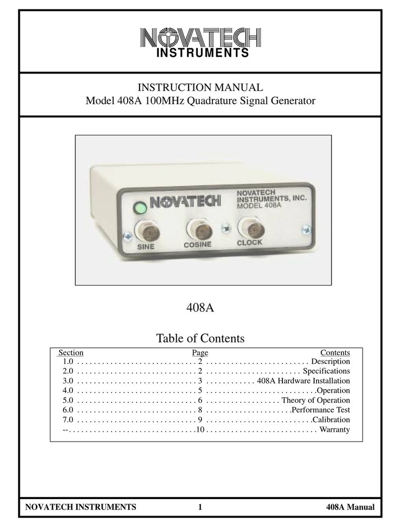
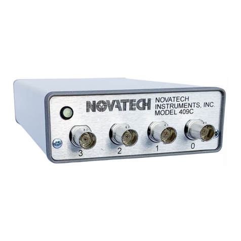
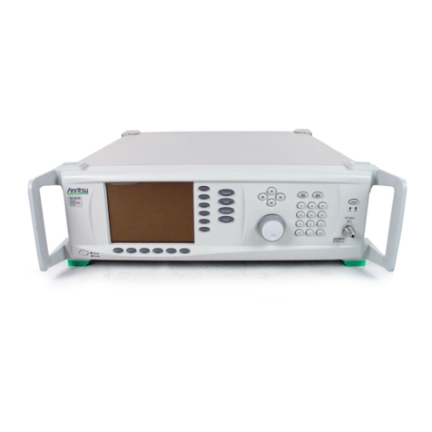
Novatech Instruments 440A User manual

NOVATECH INSTRUMENTS, INC.
206.301.8986 Voice
United States of America http://www.novatechsales.com/
sales@novatechsales.com
400MHz Programmable Signal Source
Model 440A
Specifications:
INSTRUMENTS
OUTPUT
TYPE: Sine. (optional ECL/TTL)
IMPEDANCE: 50Ω.
RANGE: 200kHz to 400MHz in 1Hz steps.
AMPLITUDE: approximately 0dBm (630mV
pp
set at
10MHz) into 50Ω.
CONTROL
Output frequency (32-bits) and phase (14-bits) are con-
trolled by sending simple text commands over a bit-serial
interface port (RS232) at 19.2kBaud. Settings can be
saved in EEPROM via the serial port.
ACCURACY AND STABILITY
Accuracy: <±1.5ppm at 10 to 40
o
C. Stable to an addi-
tional ±2ppm per year, 18 to 28
o
C. (Internal Clock)
REFERENCE CLOCK IN
LEVEL: 0.75-3.0Vrms Sine or Square Wave. 50Ω.
FREQUENCY: Programmable from 1MHz to 25MHz, in
8kHz steps. The 440A will track the externally supplied
reference as long as the external frequency is within
±5ppm. When locked the output frequency maintains the
accuracy and the stability of the reference clock with no
binary round-off. The external reference can be disabled
to use the internal oscillator in free-run mode.
SPECTRAL PURITY
(Typ. 50Ωload, 10MHz ref.)
Phase Noise:
<-120dBc, 10kHz offset, 10MHz output.
Spurious: <-55dBc below 10MHz (typ. 500MHz span)
<-50dBc below 80MHz
<-45dBc below 160MHz
<-35dBc below 400MHz
Harmonic: <-60dBc below 1MHz
<-55dBc below 20MHz
<-50dBc below 80MHz
<-40dBc below 160MHz
<-35dBc below 400MHz
POWER REQUIREMENTS
+5VDC (+4.75 to +5.25) @<1.0A. (90-240VAC with
provided AC-adapter)
SIZE
39mm H, 107mm W, 172mm L, not including connectors.
Shielded aluminum case.
ENVIRONMENTAL
Temperature: 0oC to +50oC operating.
Humidity: 80% to 31oC, decreasing linearly to 50% at
40oC.
CONNECTORS
Sine: front panel SMA; Reference In: rear panel BNC.
RS232 control: DE9F on rear panel. +5V DC Power:
2.5mm power receptacle, center positive.
The Model 440A Programmable Signal Source generates a low dis-
tortion sinewave signal from 200kHz to 400MHz with 1Hz resolu-
tion. The 440A contains an internal temperature compensated crystal
oscillator that can be locked to an external reference in 8kHz steps,
allowing the 440A to lock to common telecom signals, such as T1
and E1 rates, as well as common instrumentation frequencies such as
5MHz and 10MHz without external hardware. When locked, the
accuracy and stability of the 440A will match that of the reference.
The relative phase of the 440A can be controlled with 14-bits of res-
olution. The 440A is set by sending simple text commands over a
19.2kBaud serial interface. Four 440A can be mounted in a 1U rack
and eight in a 2U rack with optional rack adapters. The 440A oper-
ates from a single +5VDC power supply (AC-line adapter provided).

RS232 Command
Function
F0 xxx.xxxxxx
Set Frequency Zero in MHz to nearest 1Hz. Decimal point required. Maximum
‘F0’
setting is 402.653183MHz
Fr xx.xxx
Sets the Reference Frequency in MHz in 8kHz steps. Decimal point required. Range:
1MHz to 25MHz. This value is used to phase lock the internal master clock to the
externally supplied clock. Software rounds down to lowest 8kHz multiple.
P0 N
Set Phase Zero. N is an integer from 0 to 16383. Phase is set to N*360/16384 degrees
(N*
π
/8192 radians). This command sets the relative phase of the output sine wave. This is
useful for adjusting the phase of the output after the 440A has obtained lock. Factory
default is N=0.
C x
E
nable (x=E) or
D
isable (x=D) external lock. When disabled, the internal TCXO is used
without locking to an externally supplied clock.
E x
Serial Echo Control. x=D for Echo
D
isable, x=E for Echo
E
nable. Default is
E
nabled.
T x
ECL Output Control. x=D for ECL
D
isable, x=E for ECL
E
nable. Default is
D
isabled.
(requires internal configuration)
S
Save current state into EEPROM and sets the EEPROM valid flag. The state saved is used
as default upon next power up or reset.
STOP
Turns off the internal microprocessor. The
“STOP”
command automatically saves all
present settings. Use this command in embedded applications for lowest system noise and
power. A logic low (open collector) pulse must be applied to the CLR_STOP* connector
pin to restore normal operation. After a CLR_STOP* pulse, factory defaults are restored.
(an internal on-board push button implements the “CLR_STOP*” pulse)
R
Reset. This command resets the unit. EEPROM data is preserved and, if valid, it is used
upon restart. This is the same as cycling power or toggling the open collector RES* line
on the connector. (an internal on-board push button implements a “RES*” pulse)
CLR
Clear. This command clears the EEPROM valid flag and restores all factory default
values.
QUE
Read present frequency, phase and status. Returns a character string of internal settings,
lock status and software revision number. Hexadecimal format. See operating notes for
details.
Pin
Number
Function
Type
Pin
Number
Function
Type
1
Ground (Power Supply Common)
PS
2
NC (open: for LPO30A compatibil-
ity)
-
3
TX, serial ASCII data FROM mod-
ule, TTL level (3.3 V CMOS)
Out
4
Ground (Power Supply Common)
PS
5
NC (open: for LPO30A compatibil-
ity)
-
6
RX, serial ASCII data TO module,
TTL level (3.3 V CMOS)
In
7
+3.3 VDC
INPUT
PS
8
RES*, Open Collector Reset Pin,
normally left open.
In
9
Ground (Power Supply Common)
PS
10
CLR_STOP*, Open Collector Input
Pin. Pulsing low clears module to
factory default outputs and settings.
In
11
INLOCK (TTL level, 3.3 V CMOS),
Out
12
Ground (Power Supply Common)
PS
13
RF_IN, Reference Clock Input, 50
Ω.
In
14
Ground (Power Supply Common)
PS
P1 Header Pinout (LPO400A only)
Serial Commands

Operating Notes for assembly LPO400A/440A, with REV 1.x Software
.
(August 23, 2005)
1:
The ‘
QUE
’ command has be rewritten to provide data specific to the LPO400A. The command returns
a thirty-three character ASCII string terminated by a CRLF. Values are in Hexadecimal:
0000 02625A00 2710 00000078 03 10
Decoding:
0000
Relative phase in Hex. Maximum value of ‘
3fff
’. Set by
“P0”
command.
02625A00
32-bit Frequency data (4-bytes), as hexadecimal. This value is the frequency in
0.25Hz steps. 10.0MHz default value. Set by
“F0”
command
2710
Reference frequency
set by ‘
Fr
’ command. Software sets to lowest 8kHz bound-
ary. Saved as a hex value as kHz. 10000 (as hexadecimal), for 10MHz reference
frequency, default.
00000078
Control Register values. These are internal setup values.
03
This byte contains status bits. The LSB is the lock bit. If an out-of-lock condition
is detected, the bit will go low (even). ‘
03
’ means that the LPO400A has been
locked. The on-board microcomputer reads the lock pin every millisecond and
sets this value low upon detection of a out-of-lock. Approximately one minute is
required for complete lock detection.
10
Software revision as ‘
x.x
’ or Rev 1.0 for this example.
2:
The InLock Pin on the interface connector, pin 11 of P1, will be steady logic high during lock. During
the locking process, this pin may be erratic. It is suggested that, if you use this pin, it be polled. The on-
board microprocessor reads the lock status each millisecond and requires 2
16
in-lock levels in a row for
lock detection (approximately one minute). The lock detect process cannot detect minor changes in the
reference input or the lock frequency setting (>±100ppm error may still indicate lock). This pin is not
accessible on the Model 440A. On the 440A, the lock condition is indicated by the front panel LED.
When illuminated GREEN, the unit is in lock, or using internal clock. When illuminated RED the unit is
out of lock (missing external reference, or internal failure).
3:
Commands return ‘
OK
’ if parsed and executed correctly.
4:
The on board green LED is illuminated when both on-board loops are in “Lock,” or the external refer-
ence has been disabled. If the LED is not illuminated, then a lock error is indicated. See 2 (above) for
front panel LED indications for the Model 440A.

The LPO400A evaluation board is similar to the 440A, but is supplied without a case to make evaluation
of the LPO400A module easier. See the board parts placement diagram and schematic below for details
on the evaluation board.

Ext Reference Input
RS232 POWER
SINE OUT
LPO400A Evaluation Board TOP
LOCK
LED

Date: August 4, 2005Sheet 1 of 1
Size Document Number REV
BA
Title
Test Board for LPO400A
Proprietary Information
Seattle, Washington 98155 USA
Copyright 2005 Novatech Instruments, Inc.
J5
SMA
OUT+
12
W1
HDR2
12
11
10
U3C
10H350
9
10
6
7
U4B
10H116
12
13
14
15
U4C
10H116
+5D
C13
0.1
R5
10k
LPO400A TEST INTERFACE FIXTURE
C14
0.1
+5D
4
3
2
11
6
89
U3A
10H350
NOT USED
+5D
OE
13
14
15
U3D
10H350
J7
MCX
+5D
FROM LPO400A
R6
51
C15
0.1
C16
0.1
4
5
2
3
11
6
81
1
U4A
10H116
U4 and U3
SOCKETS ONLY
5
6
7
U3B
10H350
J6
SMA
12
W3
HDR2
OUT+
OUT-
12
W4
HDR2
OUT-
12
W2
HDR2
+5
C10
0.1
C
1
R
1
2
R
2
3
R
3
4
R
4
5
R
5
6
R
6
7
R
7
8
Z1
270z
+3.3
VI G
N
D
VO
U1
LM1086CT-3.3V
HS
+5
1
2
L6
BEAD
+5D
C17
10/16
TANT
O3
I
1G
2
L4
EMI BEAD
1
2
P4
MOLEX
R3
RUE185
+5V
C3
0.1 FILM
O3
I
1G
2
L5
EMI BEAD
C4
0.1 FILM
CR2
90SQ045
C5
470/10
FM
C6
470/10
FM
C9
0.1
C1+
1
C1-
3
C2+
4
C2-
5
V
C
C
1
6
V+ 2
V- 6
T1O 14
T2O 7
R1I 13
R2I 8G
N
D
1
5
R2O
9
R1O
12
T2I
10
T1I
11
U2
MAX243
C11
0.1
C12
0.1
RF OUT
J3
MCX
J4
SMA
TRAN
C2
100p
FROM LPO400A
CR1
1N5711
C8
0.1
LD
RX
+3.3
12
34
56
78
910
11 12
13 14
A1
SOCK14
TX
REF_IN
J1
BNC
METAL
+3.3
R2
0.0
C7
10/16
TANT
LD
RESc-
7x2 0.1" GRID
CLR-
SOCKET PIN STRIP
RES*
S2
PB
R1
1.00k
C1
100p
REC
R4
1.0k
J8
NL
12
W5
NL
12
W6
NL
FOR ON BOARD
MCX. NL.
1
2
P5
HDR2
F_LED
lpo400ev.sch
CLR_STOP*
S1
PB
P1
MIN BANANA
0.138 HOLES
P6
MIN BANANA
19.2kBaud
TO PC
12
L1
BEAD
5
9
4
8
3
7
2
6
1
J2
DB9-F
12
L2
BEAD
12
L3
BEAD
REC
TRAN
P2
MIN BANANA
NOT INSTALLED
P3
MIN BANANA

0
0
2.35
2.35
PIN 1, SQUARE PAD,
(1.475,0.225), P1. MCX,
JOHNSON COMPONENTS
133-3701-133
(1.825,0.175)
Mounting Holes at:
(0.175,0.175), (2.175,0.175),
(2.175,2.175), (0.175,2.175)
LPO400A, COMPONENT SIDE VIEW
P1 two rows by seven pos.,
on 0.1 (2.54mm) grid. FCI
Dubox #68683-307 or Amp
#534998-7.

WARRANTY
NOVATECH INSTRUMENTS warrants that all instruments it manufactures are free from defects in
material and workmanship and agrees to replace or repair any instrument found defective during a
period of one year from date of shipment to original purchaser.
This warranty is limited to replacing or repairing defective instruments that have been returned by
purchaser, at the purchaser's expense, to NOVATECH INSTRUMENTS and that have not been
subjected to misuse, neglect, improper installation, repair alteration or accident. NOVATECH
INSTRUMENTS shall have the sole right to final determination regarding the existence and cause of a
defect.
This warranty is in lieu of any other warranty, either expressed or implied, including but not limited to
any warranty of merchantability or fitness for a particular purpose. In no event shall seller be liable for
collateral or consequential damages. Some states do not allow limitations or exclusion of consequential
damages so this limitation may not apply to you.
All instruments manufactured by NOVATECH INSTRUMENTS should be inspected as soon as they
are received by the purchaser. If an instrument is damaged in shipment the purchaser should
immediately file a claim with the transportation company. Any instrument returned to NOVATECH
INSTRUMENTS should be shipped in its original shipping container or other rigid container and
supported with adequate shock absorbing material.
This warranty constitutes the full understanding between NOVATECH INSTRUMENTS and the
purchaser and no agreement extending or modifying it will be binding on NOVATECH INSTRUMENTS
unless made in writing and signed by an authorized official of NOVATECH INSTRUMENTS.
NOVATECH INSTRUMENTS
United States of America
TEL: 206.301.8986
http://www.novatechsales.com
sales@novatechsales.com
Table of contents
Other Novatech Instruments Portable Generator manuals
Popular Portable Generator manuals by other brands
SDMO
SDMO I-PRO 3000 Series Instruction and maintenance manual
Sincro
Sincro ER Series Use and maintenance manual
Aremeca
Aremeca CEH Series operating instructions

BANDELIN
BANDELIN SONOREX TECHNIK TG Series Assembly instructions

Kato Engineering
Kato Engineering Standard AC Generator instruction manual

Intermatic
Intermatic IPURE installation manual
