manuals.online logo
Brands
  1. Home
  2. •
  3. Brands
  4. •
  5. Eaton
  6. •
  7. Switch
  8. •
  9. Eaton PDI WaveStar BCMS User manual

Eaton PDI WaveStar BCMS User manual

p/n: P-164001108
Revision 01
Installation and Operation Manual
Eaton®PDI WaveStar BCMS Hub
Eaton reserves the right to change specifications ithout prior notice. Eaton is a registered trademark of Eaton. PDI, JCOMM, Quad-Wye,
ToughRail Technology, and WaveStar are registered trademarks of Po er Distribution Inc. All other trademarks are held by their
respective o ners. All other trademarks are property of their respective companies.
©Copyright 2023 Eaton, Raleigh, NC, USA. All rights reserved. No part of this document may be reproduced in any ay ithout the
express ritten approval of Eaton.
Thank you for your recent purchase of an Eaton PDI WaveStar BCMS Hub.
For safety reasons as well as to ensure opt mal performance of your Eaton PDI WaveStar BCMS Hub,
please carefully read the nstruct ons before try ng to nstall, operate, serv ce or ma nta n the system.
For any quest ons regard ng the nstallat on, operat on, serv ce or ma ntenance, contact the Eaton Help
Desk. See paragraph 2.7 Getting Help for deta ls.
Please use the follow ng e-ma l for manual comments, suggest ons, or to report a techn cal error n
th s manual.
E-ESSDocumentat [email protected]
You can download the most recent vers on of th s product manual from the Eaton web s te’s Product
page, Resources sect on:
https://www.eaton.com/us/en-us/catalog/low-voltage-power-d str but on-controls-systems/eaton-pd -
busway.resources.html
Eaton PDI WaveStar BCMS Hub Installation and Operation Manual
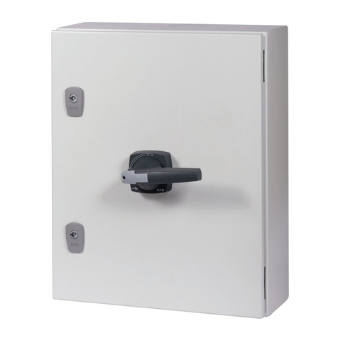
Cover Photo: Eaton PDI WaveStar BCMS Hub
Dear Customer,
On behalf of everyone at Eaton, we thank you for partnering
with us, and trusting us to maintain your business continuity
and preventing downtime at your facility.
Our suite of backup power, power distribution and power
management products are designed to protect you from a host
of threats including power outages, surges, lighting strikes, and
enable you to monitor and control your power infrastructure.
We trust that your Eaton Uninterruptible Power Supply system
and Accessory Products, will deliver high quality, reliable
backup power for your business, and we are committed to your
success.
Please read this Installation and Operation Manual, which
details the installation, and operation processes for your
uninterruptible power supply system.
Thank you for choosing Eaton!
Eaton PDI WaveStar BCMS Hub Installation and Operation Manual P-164001108—Rev 01 v
TTaabbllee ooff CCoonntteennttss
11 SSaaffeettyy......................................................................................................................................................................................................................................................................................................................11
22 IInnssttaallllaattiioonn PPllaannnniinngg............................................................................................................................................................................................................................................................................33
2.1 BCMS Hub and BCMS Dual Hub....................................................................................................................3
2.2 Commun cat ons ........................................................................................................................................3
2.3 Supported Dev ces .....................................................................................................................................4
2.4 Excluded Dev ces .......................................................................................................................................5
2.5 Mon tors...................................................................................................................................................5
2.6 Electr cal Loads and Modbus Addresses..........................................................................................................5
2.6.1 Modbus Segments ...............................................................................................................................5
2.6.2 Count ng Electr cal Loads and Modbus Addresses .......................................................................................6
2.6.3 Examples, Max mum Conf gurat ons.........................................................................................................6
2.6.4 Determ n ng Modbus Addresses..............................................................................................................6
2.7 Gett ng Help..............................................................................................................................................8
2.8 Warranty...................................................................................................................................................8
33 IInnssttaallllaattiioonn ......................................................................................................................................................................................................................................................................................................99
3.1 Mount ng and Condu t .................................................................................................................................9
3.2 Customer Connect ons BCMS Hub ................................................................................................................9
3.2.1 Customer Power Connect ons............................................................................................................... 10
3.2.2 Customer Commun cat ons Connect ons ................................................................................................. 11
3.3 Customer Connect ons BCMS Dual Hub........................................................................................................ 13
3.3.1 Customer Power Connect ons, BCMS Dual Hub........................................................................................ 14
3.3.2 Customer Commun cat ons Connect ons, BCMS Dual Hub.......................................................................... 14
3.4 Customer Connect ons for Mon tored Equ pment............................................................................................ 16
3.4.1 Remote Power Panel (RPP) Modbus RTU Connect ons............................................................................... 16
3.4.2 JCOMM Modbus RTU Connect ons........................................................................................................ 17
3.4.3 Bus System End Feed Modbus RTU Connect ons...................................................................................... 18
44 SSyysstteemm SSeettuupp............................................................................................................................................................................................................................................................................................ 2211
4.1 Adm n strat ve Setup................................................................................................................................. 21
4.1.1 Logg ng In/Logg ng Out........................................................................................................................ 21
4.1.2 Access Level ..................................................................................................................................... 21
4.1.3 In t al Adm n strator Access................................................................................................................... 22
4.1.4 Users Screen..................................................................................................................................... 22
4.2 Sett ngs Screen........................................................................................................................................ 23
4.2.1 ModBus Sett ngs................................................................................................................................ 23
4.2.2 Ethernet Sett ngs................................................................................................................................ 24
4.3 T me Sett ngs .......................................................................................................................................... 25
4.3.1 Manual T me Sett ng ........................................................................................................................... 25
4.3.2 T me Synchron zat on Sett ngs Screen (SNTP)........................................................................................... 25
vi Eaton PDI WaveStar BCMS Hub Installation and Operation Manual P-164001108—Rev 01
4.4 Alarm Not f cat on..................................................................................................................................... 26
4.4.1 Alarm Not f cat on by Ema l ................................................................................................................... 27
4.4.2 Alarm Not f cat on by Modem ................................................................................................................ 27
4.5 Other Screens ......................................................................................................................................... 28
55 OOppeerraattiioonn:: DDee iiccee IInnffoorrmmaattiioonn............................................................................................................................................................................................................................................ 3311
5.1 Home Screen .......................................................................................................................................... 31
5.2 Startup Scans .......................................................................................................................................... 31
5.3 V ew ng Dev ce Informat on ........................................................................................................................ 32
5.4 Clear ng Alarms and Warn ngs..................................................................................................................... 32
5.5 Bus System Dev ce Informat on................................................................................................................... 32
5.5.1 End Feed .......................................................................................................................................... 32
5.5.2 Tap-Off Box....................................................................................................................................... 33
5.6 Panelboard Dev ce Informat on.................................................................................................................... 35
5.6.1 BCMS Normal/KWH Po nts L sts............................................................................................................ 36
5.6.2 BCMS IEC Po nts L st .......................................................................................................................... 37
5.7 Event Log ............................................................................................................................................... 39
5.7.1 Download Event Log to PC ................................................................................................................... 39
66 OOppeerraattiioonn:: WWeebb PPaaggeess .................................................................................................................................................................................................................................................................. 4411
77 GGlloossssaarryy .......................................................................................................................................................................................................................................................................................................... 4433
88 BBiibblliiooggrraapphhyy .............................................................................................................................................................................................................................................................................................. 4455
Table of Contents
Eaton PDI WaveStar BCMS Hub Installation and Operation Manual P-164001108—Rev 01 vii
LLiisstt ooff FFiigguurreess
F gure 1. WaveStar BCMS Hub and BCMS Dual Hub.......................................................................................... 3
F gure 2. BCMS Hub and BCMS Dual Hub Networks.......................................................................................... 4
F gure 3. Count ng Electr cal Loads and Modbus Addresses.................................................................................7
F gure 4. BCMS Hub and BCMS Dual Hub Enclosures ........................................................................................ 9
F gure 5. Internal Panels as Manufactured...................................................................................................... 10
F gure 6. Customer Connect ons, Power and Commun cat ons, Left Ins de Panel................................................... 11
F gure 7. Customer Commun cat ons Connect ons, R ght Ins de Panel ................................................................. 13
F gure 8. Customer Connect ons, BCMS Dual Hub, Left Ins de Panel................................................................... 14
F gure 9. RPP Modbus Connect ons ............................................................................................................. 17
F gure 10. JCOMMs w th and w thout Mon tor ................................................................................................. 17
F gure 11. JCOMM Modbus Connect ons........................................................................................................ 18
F gure 12. Accumulator PCB Locat ons, PowerWave 2 Bus Systems..................................................................... 19
F gure 13. Accumulator PCB Modbus Connect ons............................................................................................ 19
F gure 14. Logg ng In and Out from Home Screen ............................................................................................. 21
F gure 15. Users Screen .............................................................................................................................. 22
F gure 16. Sett ngs Screen ........................................................................................................................... 23
F gure 17. Modbus Sett ngs: Modbus Address Offset ........................................................................................ 24
F gure 18. TIME Screen ............................................................................................................................... 26
F gure 19. Ema l Setup Screen ...................................................................................................................... 27
F gure 20. Modem Setup Screen ................................................................................................................... 28
F gure 21. Conf gurat on Screen .................................................................................................................... 29
F gure 22. Home Screen .............................................................................................................................. 31
F gure 23. End Feed Summary Screen ............................................................................................................ 32
F gure 24. End Feed Add t onal Dev ce Screens ................................................................................................ 33
F gure 25. Tap-Off Box Screens..................................................................................................................... 34
F gure 26. Panelboard BCMS: KWH Po nts L st................................................................................................. 36
F gure 27. Panelboard BCMS: Screen Controls for KWH Po nts L st ...................................................................... 37
F gure 28. Panelboard BCMS: IEC Po nts L st ................................................................................................... 38
F gure 29. Event Log................................................................................................................................... 39
F gure 30. Web Dev ces Page ....................................................................................................................... 41
F gure 31. Panelboard Dev ce Web Page ......................................................................................................... 42
F gure 32. Event Log Download from Web ...................................................................................................... 42
viii Eaton PDI WaveStar BCMS Hub Installation and Operation Manual P-164001108—Rev 01
List of Figures
Eaton PDI WaveStar BCMS Hub Installation and Operation Manual P-164001108—Rev 01 1
CChhaapptteerr 11 SSaaffeettyy
Please pay spec al attent on to the use of “Danger” symbols throughout th s manual nd cat ng electr cal or
other safety hazards. Follow ng these safety nstruct ons s extremely mportant to avo d poss ble njury or
death.
Th s symbol s used throughout th s manual to nd cate the presence of h gh voltages, represent ng a hazard for
electr c shock, burn or explos on. Follow the nstruct ons carefully to avo d ser ous or fatal njury.
Follow safe electr cal work pract ces:
• D sconnect and lock-out all power supply ng equ pment before work ng on or nstall ng WaveStar® BCMS
Hub components. Use a properly rated voltage sens ng dev ce to conf rm power s OFF.
• Electr cal equ pment should be nstalled, operated, serv ced, and ma nta ned only by qual f ed personnel
and n accordance w th all local safety codes. Eaton assumes no respons b l ty for any consequences
ar s ng out of the use of th s manual. Th s document should not be v ewed as suff c ent by otherw se non-
qual f ed personnel to operate, serv ce, or ma nta n the equ pment d scussed.
• Read, understand, and follow the nstruct ons before nstall ng th s product.
• Install dev ce n an appropr ate electr cal enclosure per local regulat ons.
• ESD sens t ve equ pment. Ground yourself, d scharge any stat c charge and ensure that the dev ce s
effect vely grounded before handl ng the un t.
2 Eaton PDI WaveStar BCMS Hub Installation and Operation Manual P-164001108—Rev 01
Safety
Eaton PDI WaveStar BCMS Hub Installation and Operation Manual P-164001108—Rev 01 3
CChhaapptteerr 22 IInnssttaallllaattiioonn PPllaannnniinngg
The Eaton®PDI WaveStar®BCMS Hub prov des a consol dated power mon tor ng stat on for v ew ng the status
of numerous dev ces, such as branch c rcu t panel boards or Bus System End Feeds and Tap-Off Boxes that
use Eaton’s Branch C rcu t Mon tor ng System (BCMS). Mon tor ng data s d splayed on a 10.4- n color
touchscreen. Mon tor ng data can also be d splayed remotely on web pages us ng a TCP/IP l nk.
Each BCMS Hub has a s ngle downstream Modbus RTU l nk to ts mon tored dev ces w th up to (32)
connect ons or drops and up to (246) total Modbus addresses. The max mum conf gurat on var es depend ng
on the type of equ pment be ng mon tored. See paragraph 2.6 Electrical Loads and Modbus Addresses for
examples.
A BCMS Dual Hub doubles the mon tor ng capac ty w th n the same s ze enclosure us ng a second Mon tor.
NOTE Eaton now handles all serv ce and support for products prev ously manufactured by
Power D str but on, Inc (PDI). See paragraph 2.7 Getting Help for contact nformat on.
22..11 BBCCMMSS HHuubb aanndd BBCCMMSS DDuuaall HHuubb
A BCMS Hub enclosure can house a s ngle BCMS Hub or a BCMS Dual Hub. The BCMS Dual Hub has two (2)
BCMS Hub systems, wh ch operate ndependently except for shar ng the same power supply.
Figure 1. WaveStar BCMS Hub and BCMS Dual Hub
22..22 CCoommmmuunniiccaattiioonnss
The BCMS Hub has a s ngle downstream l nk to mon tored BCMS dev ces that uses Modbus RTU at 9600 bps.
The BCMS Hub can have one (1) or two (2) upstream l nks to a Bu ld ng Management System (BMS) or Data
Center Infrastructure Management (DCIM) system:
• (1) Modbus RTU l nk at 19,200 or 9600 bps
• (1) TCP/IP us ng Ethernet cable, prov d ng
–Web server connect on for remotely v ew ng BCMS Hub web pages, and/or
–Modbus TCIP/IP connect on to BMS or DCIM system
4 Eaton PDI WaveStar BCMS Hub Installation and Operation Manual P-164001108—Rev 01
The Modbus RTU and the TCP/IP l nks can be used s multaneously. A BMS system can use Modbus RTU to
the BCMS Hub and a DCIM system can use TCP/IP wh le web pages are s multaneously d splayed over the
TCP/IP l nk.
D stances restr ct ons:
• For Modbus RTU, cable lengths should be ≤ 2000 ft.
• For upstream Ethernet l nks, apply standard Ethernet length restr ct ons for the cable used (Cat5, Cat5e,
etc.)
The BCMS Dual Hub has (2) separate BCMS Hub systems n the same enclosure, each w th ts own Mon tor.
Each system has exactly the same capac ty, opt ons, and restr ct ons as a s ngle BCMS Hub.
Figure 2. BCMS Hub and BCMS Dual Hub Net orks
22..33 SSuuppppoorrtteedd DDee iicceess
The BCMS Hub collects mon tor ng data from BCMS devices. Techn cally a BCMS dev ce s a BCMS points
list (or Modbus reg ster map), represent ng a phys cal component, such as a panelboard. A s ngle BCMS PCB
can have mult ple po nts l sts and appear as mult ple dev ces. For example, a BCMS PCB for panelboards
typ cally has two (2) po nts l sts, one for each panelboard t supports.
The follow ng equ pment and BCMS dev ces can be mon tored by a BCMS Hub, f BCMS s nstalled w th the
mon tored equ pment:
•RPPs and JCOMMs, mon tor ng panelboards and the r nput feeds w th any of these po nts l sts:
• BCMS Normal, the default po nts l st for North Amer can panelboards
Installation Planning
Eaton PDI WaveStar BCMS Hub Installation and Operation Manual P-164001108—Rev 01 5
• BCMS KWH, a po nts l st prov d ng branch c rcu t power usage nformat on for standard North Amer can
panelboards
• BCMS IEC, the po nts l st prov d ng power nformat on from IEC panel boards
•Bus ay Products (PowerWave Bus Systems™, PowerWave 2™ Bus Systems, and PowerWave S lver™
Bus Systems):
• End Feeds us ng the PM Input Board po nts l st
• Tap-Off Boxes, us ng the Bus po nts l st
22..44 EExxcclluuddeedd DDee iicceess
The BCMS Hub does not support data collect on and d splay from the follow ng dev ces:
• WaveStar Power D str but on Un ts (PDUs) (PowerPak, PowerHub, or PowerHub 2 PDUs)
• BCMS us ng the Enhanced Subfeeds po nts l st (large PDU feeds)
• WaveStar Stat c Transfer Sw tch
• Non-Eaton equ pment, except for panelboards mon tored through a JCOMM
22..55 MMoonniittoorrss
WaveStar Color Mon tors and WaveStar Mon tors (monochrome) can be ncluded n the downstream dev ce
cha n from the BCMS Hub. However, the PowerWave Bus Systems™ 7- nch Local D splay, wh ch s also used
w th PowerWave 2™ Bus Systems and PowerWave S lver™ Bus Systems, cannot be used on the Hub’s
downstream Modbus cha n.
22..66 EElleeccttrriiccaall LLooaaddss aanndd MMooddbbuuss AAddddrreesssseess
The downstream l nk from the BCMS Hub to ts mon tored dev ces has standard Modbus RTU restr ct ons:
• Up to (32) electr cal loads or drops along the downstream dev ce cha n. Each connect on along the Modbus
RTU bus s an electr cal load.
• Up to (246) total Modbus addresses on the downstream dev ce cha n. Each po nts l st has a Modbus
address, nclud ng Mon tors.
22..66..11 MMooddbbuuss SSeeggmmeennttss
Mon tors create Modbus segments cons st ng of the Mon tor and ts downstream dev ces. Mon tors are
Modbus cl ents on the r own Modbus segments:
• The BCMS Hub s the cl ent on ts downstream segment.
• A Mon tor on a RPP or JCOMM s the cl ent on ts Modbus segment, wh ch usually has just the BCMS
dev ces (panelboards) n the RPP or JCOMM. Because these dev ces are n a separate Modbus segment,
they are not d rectly addressable from the BCMS Hub; the Hub retr eves data from these dev ces by
address ng the Mon tor.
If an RPP or JCOMM has a Mon tor, the Mon tor connect on s the electr cal load, and the BCMS cards n the
RPP or JCOMM are not electr cal loads. However, f there s no Mon tor, each BCMS card s an electr cal load
because the BCMS cards are d rectly addressable from the Hub and s part of the Hub’s downstream Modbus
segment.
For Bus Systems, the Accumulator Board n End Feed s Modbus cl ent to ts Tap-Off Boxes. (The 7" Local
Busway D splay cannot be used w th the BCMS Hub.)
Installation Planning
6 Eaton PDI WaveStar BCMS Hub Installation and Operation Manual P-164001108—Rev 01
22..66..22 CCoouunnttiinngg EElleeccttrriiccaall LLooaaddss aanndd MMooddbbuuss AAddddrreesssseess
You must be sure to stay w th n the Modbus l m ts. F gure 3 llustrates count ng electr cal loads and Modbus
addresses on the BCMS Hub downstream l nk to ts dev ces.
22..66..33 EExxaammpplleess,, MMaaxxiimmuumm CCoonnffiigguurraattiioonnss
The follow ng are examples of max mum conf gurat ons for e ther electr cal loads or Modbus addresses:
(32) RPPs or JCOMMs each w th Mon tors, (2) BCMS PCBs, and (4) panelboards (Mon tors are the electr cal
loads):
• (32) RPPs or JCOMMs w th Mon tors = (32) Electrical Loads (max mum)
• (32) RPP or JCOMMs each w th (1) Mon tor and (4) PBs = 32 x 5 = (160) Modbus addresses
(16) RPPs or JCOMMs w thout Mon tors, each w th (2) BCMS PCBs and (4) panelboards (BCMS PCBs are the
electr cal loads):
• (2) BCMS PCBs per RPP or JCOMM: 16 RPPs/JCOMMs x 2 PCBs = (32) Electrical Loads (max mum)
• (4) Panelboards per RPP or JCOMM: 16 RPPs/JCOMMs x 4 PBs = (64) Modbus addresses
(24) Bus System End Feeds w th (9) Tap-Off Boxes each:
• (24) End Feeds = (24) Electr cal Loads
• (24) Bus Runs w th (10) addresses each (1 End Feed + 9 Tap-Off Boxes) = (240) Modbus Addresses (near
max mum)
22..66..44 DDeetteerrmmiinniinngg MMooddbbuuss AAddddrreesssseess
Mon tors are Modbus cl ents on the r segment and adjust the Modbus addresses of the r downstream dev ces
based on the r own address. Because the BCMS Hub s a Modbus cl ent and Mon tors downstream n RPPs or
JCOMMs are also Modbus cl ents on the r own segments, mult ple address adjustments can occur. These
address adjustments can be confus ng.
On the BCMS Hub Home screen you have a cho ce of show ng dev ces Modbus addresses as seen from the
BCMS Hub or Modbus addresses as seen from the BMS or DCIM system (assum ng the BMS or DCIM s next
upstream from the Hub). Us ng Offset = √ on Modbus Settings w ll show addresses on the Home screen as
seen from the BMS. Th s sett ng s recommended because t makes t easy to coord nate Modbus addresses
between the BCMS Hub and the BMS. See paragraph 4.2.1 ModBus Settings.
Installation Planning
Eaton PDI WaveStar BCMS Hub Installation and Operation Manual P-164001108—Rev 01 7
Figure 3. Counting Electrical Loads and Modbus Addresses
Installation Planning
8 Eaton PDI WaveStar BCMS Hub Installation and Operation Manual P-164001108—Rev 01
22..77 GGeettttiinngg HHeellpp
If help s needed w th any of the follow ng:
• Schedul ng n t al startup
• Reg onal locat ons and telephone numbers
• A quest on about any of the nformat on n th s manual
• A quest on th s manual does not answer
Please call the Eaton Help Desk at:
Un ted States: 1-800-843-9433 or 1-919-870-3028
Canada: 1-800-461-9166 ext 260
All other countr es: Call your local service representative
Please use the follow ng e-ma l for manual comments, suggest ons, or to report a techn cal error n th s manual.
[email protected]
22..88 WWaarrrraannttyy
To v ew the warranty please cl ck on the l nk or copy the address to download from the Eaton webs te:
Eaton Product Warranty
https://www.eaton.com/content/dam/eaton/products/backup-power-ups-surge- t-power-d str but on/backup-
power-ups/portfol o/eaton-three-phase-ups-warranty.pdf
Installation Planning
Eaton PDI WaveStar BCMS Hub Installation and Operation Manual P-164001108—Rev 01 9
CChhaapptteerr 33 IInnssttaallllaattiioonn
Th s product must be nstalled and nspected by l censed electr c ans or by Eaton-author zed techn c ans. Th s
document should not be v ewed as suff c ent by otherw se non-qual f ed personnel to operate, serv ce, or
ma nta n th s equ pment.
Severe or fatal njury can result from electr cal shock dur ng contact w th h gh voltage conductors, mon tor ng
PCBs, or s m lar equ pment!
• D sconnect power before dr ll ng holes, mak ng cutouts, attach ng condu t, or connect ng to PDUs, RPPs,
or other power d str but on equ pment.
• Use Lock Out/Tag Out procedures.
• Wear su table personal protect ve cloth ng and use protect ve equ pment for perform ng mechan cal and
electr cal nstallat ons.
• Leave ample space for attach ng and rout ng w res.
33..11 MMoouunnttiinngg aanndd CCoonndduuiitt
The enclosure for both the BCMS Hub and the BCMS Dual Hub s 24"W x 24"H x 5"D. The BCMS Hub or BCMS
Dual Hub must be securely mounted on a wall or mounted on a frame attached to poles or another sol d
surface. Customers must make the r own condu t cutouts on the enclosure.
Figure 4. BCMS Hub and BCMS Dual Hub Enclosures
33..22 CCuussttoommeerr CCoonnnneeccttiioonnss BBCCMMSS HHuubb
Customer connect ons are mostly made to the left ns de panel. F gure 5 shows ns de panels as manufactured.
F gure 6 and F gure 7 show the BCMS Hub w red for a TCP/IP upstream l nk to a BMS or DCIM system us ng
the opt onal Ethernet connect on wh le the upstream Modbus RTU l nk s not used.
10 Eaton PDI WaveStar BCMS Hub Installation and Operation Manual P-164001108—Rev 01
Figure 5. Internal Panels as Manufactured
33..22..11 CCuussttoommeerr PPoowweerr CCoonnnneeccttiioonnss
Customer prov des nput 1P 3-w re power, 100VAC – 277VAC, 50 or 60 Hz. (F gure 6)
1. Connect hot w re (black) to bottom of r ght fuse.
2. Connect neutral (wh te) to bottom of left fuse.
3. Connect ground (green) to the fuse DIN ra l. Ground from the fuse DIN ra l to the BCMS Hub frame s
w red at the factory.
Installation
Eaton PDI WaveStar BCMS Hub Installation and Operation Manual P-164001108—Rev 01 11
Figure 6. Customer Connections, Po er and Communications, Left Inside Panel
33..22..22 CCuussttoommeerr CCoommmmuunniiccaattiioonnss CCoonnnneeccttiioonnss
Modbus RTU protocol can be used upstream to the BMS or DCIM system as the s ngle upstream l nk or w th a
TCP/IP upstream l nk.
Modbus RTU protocol s used downstream from the BCMS n a s ngle da sy cha n to all dev ces.
Installation
12 Eaton PDI WaveStar BCMS Hub Installation and Operation Manual P-164001108—Rev 01
1RX+ GREEN
2 RX- BLACK
3SHIELD WHITE UPSTREAM
4TX+ YELLOW
5TX- RED
6RX+ GREEN
7RX- BLACK
8SHIELD WHITE DOWNSTREAM
9 TX+ YELLOW
10 TX- RED
Installation

Other Eaton Switch manuals

Eaton Ulusoy URING36 F-SF6 User manual

Eaton

Eaton Ulusoy URING36 F-SF6 User manual

Eaton P1-25-I2H-SW Manual

Eaton

Eaton P1-25-I2H-SW Manual

Eaton Magnum DS Manual

Eaton

Eaton Magnum DS Manual

Eaton COOPER POWER SERIES User manual

Eaton

Eaton COOPER POWER SERIES User manual

Eaton ATR Manual

Eaton

Eaton ATR Manual

Eaton ATHA Manual

Eaton

Eaton ATHA Manual

Eaton WFSW15 User manual

Eaton

Eaton WFSW15 User manual

Eaton TM-1-8210 Series Manual

Eaton

Eaton TM-1-8210 Series Manual

Eaton DILMP Series Manual

Eaton

Eaton DILMP Series Manual

Eaton 9476-ET User manual

Eaton

Eaton 9476-ET User manual

Eaton CTSA-0./04 Manual

Eaton

Eaton CTSA-0./04 Manual

Eaton COOPER POWER SERIES Operating instructions

Eaton

Eaton COOPER POWER SERIES Operating instructions

Eaton H-T6-160 Series Manual

Eaton

Eaton H-T6-160 Series Manual

Eaton Crouse-hinds series User manual

Eaton

Eaton Crouse-hinds series User manual

Eaton Tripp-Lite B005-HUA2-K User manual

Eaton

Eaton Tripp-Lite B005-HUA2-K User manual

Eaton TM-1-8290/E/SVB Manual

Eaton

Eaton TM-1-8290/E/SVB Manual

Eaton DeviceNet E50DNA User manual

Eaton

Eaton DeviceNet E50DNA User manual

Eaton AT4 Series Manual

Eaton

Eaton AT4 Series Manual

Eaton xiria series User manual

Eaton

Eaton xiria series User manual

Eaton T3 I2H/RT Series Manual

Eaton

Eaton T3 I2H/RT Series Manual

Eaton CurrentWatch ECS Series User manual

Eaton

Eaton CurrentWatch ECS Series User manual

Eaton Power Xpert UX User manual

Eaton

Eaton Power Xpert UX User manual

Eaton ATR Series Manual

Eaton

Eaton ATR Series Manual

Eaton T03 I2-NA Series Manual

Eaton

Eaton T03 I2-NA Series Manual

Popular Switch manuals by other brands

Targus 7-PORT USB 3.0 COMBO HUB user guide

Targus

Targus 7-PORT USB 3.0 COMBO HUB user guide

NETGEAR ProSafe Plus FS116E installation guide

NETGEAR

NETGEAR ProSafe Plus FS116E installation guide

Vega VEGAVIB 63 operating instructions

Vega

Vega VEGAVIB 63 operating instructions

Supermicro MicroBlade MBM-GEM-004 Web user guide

Supermicro

Supermicro MicroBlade MBM-GEM-004 Web user guide

Advantech MicroTCA UTCA-5503 user manual

Advantech

Advantech MicroTCA UTCA-5503 user manual

LuxCom OM1004 operating manual

LuxCom

LuxCom OM1004 operating manual

TRENDnet TPE-224WS - Web Smart PoE Switch Specifications

TRENDnet

TRENDnet TPE-224WS - Web Smart PoE Switch Specifications

Advantech EKI-7657C user manual

Advantech

Advantech EKI-7657C user manual

PCB Piezotronics IMI SENSORS Y685B0001A13 Installation and operating manual

PCB Piezotronics

PCB Piezotronics IMI SENSORS Y685B0001A13 Installation and operating manual

HP ProCurve Series Installation and getting started

HP

HP ProCurve Series Installation and getting started

StarTech.com ST7CU35122 instruction manual

StarTech.com

StarTech.com ST7CU35122 instruction manual

Autonics SPB Series product manual

Autonics

Autonics SPB Series product manual

H3C S12500 Series installation instructions

H3C

H3C S12500 Series installation instructions

Gianni Industries CP-15 Series Specifications

Gianni Industries

Gianni Industries CP-15 Series Specifications

Surecom EP-517T Quick installation guide

Surecom

Surecom EP-517T Quick installation guide

Targus PA050U quick start guide

Targus

Targus PA050U quick start guide

MySmartBlinds Smart Bridge user manual

MySmartBlinds

MySmartBlinds Smart Bridge user manual

Exsys EX-1197HMS manual

Exsys

Exsys EX-1197HMS manual

manuals.online logo
manuals.online logoBrands
  • About & Mission
  • Contact us
  • Privacy Policy
  • Terms and Conditions

Copyright 2025 Manuals.Online. All Rights Reserved.