manuals.online logo
Brands
  1. Home
  2. •
  3. Brands
  4. •
  5. Siemens
  6. •
  7. Power Supply
  8. •
  9. Siemens 5WG1 125-4CB23 User manual

Siemens 5WG1 125-4CB23 User manual

P.T.O.
instabus®
Technical Manual
Decentralized Power Supply
JB 125C23, 80mA
5WG1 125-4CB23
January 2015/ Page 1
USA
Product and Application Description
The decentralized power supply unit JB 125/23 provides the
system power necessary for the instabus KNX. The device is
installed in a 4 x 4 inch junction box. The bus is connected
via a bus terminal block.
The integrated choke prevents the data telegrams from
short-circuiting on the bus line.
For each bus line, at least one decentralized power supply
unit JB 125/23 is needed. A second unit is not required
unless the supply voltage at a bus device is less than 21 V.
Up to eight decentralized power supply units JB 125/23 may
be attached in parallel to a single bus line.
Note: If two or more power supply units are operated in par-
allel on one bus line and if the overload LED is lit on one or
several power supplies, then the bus configuration has to be
changed until the overload display disappears on all units.
A minimum cable length is not required between the decen-
tralized power supplies JB 125/23. Operation of a power
supply unit N125/x2 in parallel to the decentralized power
supplies is permitted on the same bus line as long as the
sum of all short circuit currents of all power supplies does
not exceed 3A.
When several bus devices are installed in short bus cable
distance (e.g. 10 m), e.g. in distribution boards, or in a room
control box AP 641, the power supply units shall be ar-
ranged near these bus devices. The distance along the bus
wire between any bus device and the closest power supply
unit must not exceed 350 m. If only the decentralized power
supply JB125/23 is used, then the maximum KNX cable
length in a bus line is 350m for one, 700m for two, and
1000m for 3 or more decentralized power supplies
JB 125/23.
The decentralized power supply unit JB 125/23 has a volt-
age and current regulation and is therefore short-circuit
proof. Short power failures can be bridged with a backup in-
terval of at least 100 ms.
To ensure an uninterrupted power supply a separate circuit
with safety separation should be used for the mains power
supply circuit of all power supply units.
The decentralized power supply units JB 125C23 are pow-
ered by AC 120V.
Application Program
No application program required
Technical Specifications
Input voltage
• rated voltage: AC 120V, 50...60Hz
Rated power consumption
approx. 10 W
Output voltage
• rated voltage: DC 29 V (class 2)
• safety extra low voltage (SELV)
• permissible range: DC 28 ... 30 V
Output current
• rated current 80 mA
• short-circuit current: limited to 0.2 A
Backup interval
on input voltage failure: ≥100 ms at rated current
Display elements
• 1 red LED: for indicating
- a shorted-out bus line or device over-load
Connections
·Bus line : Bus connection pins for connection of the
screwless bus terminal block (red-black) 0.6…0.8 mm Ø
single core, strip insulation 5mm
·mains power:
see Location and Function of Interface Elements
Physical specifications
·housing: plastic
·dimensions (L x W x D):
length : 70 mm (2.76 inch)
width: 90 mm (3.54 inch)
depth: 44.6 mm (1.76 inch)
·weight: approx. 171 g
·fire load: approx. 5 MJ
·Installation: in a junction box (min. dimensions (L-W-D))
Length: 4 inch (101.6 mm)
Width: 4 inch (101.6 mm)
Depth: 2 inch (50.8 mm)
Electrical safety
·Degree of pollution (according to IEC 60664-1): 2
·Type of protection (according to EN 60529): IP 20
·Overvoltage category (according to IEC 60664-1): III
·Bus: safety extra low voltage SELV DC 24 V
·Device complies with: EN 50428
Electromagnetic compatibility
complies with EN 50428
Environmental specifications
·Ambient operating temperature:
- 5 … + 45 °C (+ 23 ... + 113 °F)
·Storage temperature:
- 25 … + 70 °C (- 13 ... + 158 °F)
·Relative humidity (not condensing): 5 % … 93 %
Reliability
·Failure rate: 109 fit at 40°C
Markings
EIB, KNX, UL
Listings and Certifications
CE mark
complies with the EMC regulations (residential and func-
tional buildings) and low voltage regulations
UL listed (E464611)
UL 916, Open Energy Management Equipment
L1V30356155A DS01
instabus®
Technical Manual
Decentralized Power Supply
JB 125C23, 80mA
5WG1 125-4CB23
January 2015/ Page 2
USA
Hazardous voltage.
Can cause death, or serious injury or property damage.
The device must not be opened.
A faulty device should be returned to the local Siemens sales office
or distributor.
WARNING
WARNING
The device must
be mounted and commissioned by a factory trained person.
The prevailing safety rules must be observed!
Mount in dry locations only!
Location and Function of the Interface Elements
A4
A5
A6
A7
A1
A7
A3 A3
A7
A8
A9
A1 Type label
A3 Protective lid over bus connection
A4 Bus connection terminal block for single core conduc-
tors with 0.6...0.8 mm Ø
A5 LED for indicating
- normal operating mode (LED off),
- a shorted-out bus line or device over-load (LED on)
A6 button has no function
A7 1/2 inch screw nut
A8 Wire (black) Line (Hot) (AWG #14)
A9 Wire (white) Neutral (AWG #14)
Dimension Diagram
Dimensions in mm (inch)
(2.76) (2.76)
(3.54) (1.76)
.
B1
B4
B2
B1
B3
B1 B4
B2
B3
B1 4” x 4” Junction Box
B2 Device
B3 Bus connection pins of the module for connection of
the bus terminal block for single core conductors with
0.6…0.8 mm Ø
B4 1/2 inch screw nut
Mounting and Dismounting
·Mounting of a JB module:
Option 1 (mounting inside a J-Box)
- Insert the thread of the JB module (B2) into the 1/2 inch
knockout between two adjacent J-Boxes (B1)
- Fasten the JB module (B2) with the 1/2 inch thread nut (B4)
- Remove the protective lid (B3) and connect the bus wire to
the bus terminal block (A4)
- Connect the wires from the device to the field wires using
wire nuts (not provided in package)
Option 2 (mounting outside of a J-Box)
- Insert the thread of the JB module (B2) into the 1/2 inch
knockout of the J-Box (B1)
- Fasten the JB module (B2) with the 1/2 inch thread nut (B4)
to the J-Box (B1)
- Connect the bus wire to the bus terminal block under the
protective cover (B3)
- Connect the wires from the device to the field wires using
wire nuts (not provided in package)
- Install the protective lid (B3) and fasten with screws (pro-
vided in package)
·Dismounting a JB module:
- Disconnect power to the module
- Remove the wire nuts and bus connection
- Unfasten the 1/2 inch thread nut (B4) connecting the JB
module (B2) to the J-Box (B1)
- Remove the JB module (B2) from the J-Box (B1)
C2
C2.2 C2.1
C2.3
D2
D2.4
5 mm
D2
D2.4
25...35 mm
D1
Wiring
Slipping off/on bus connection blocks
The bus connection block consists of two components (C2.1
and C2.2) with four terminal contacts each. Take care not to
damage the two test sockets (C2.3) by accidentally connect-
ing them to the bus cable or with the screw driver (e.g.
when attempting to unplug the bus connection block).
Slipping off bus connection blocks
- Carefully put the screw driver to the wire insertion slit of
the bus connection block’s grey component (C2.2)
and
- pull the bus connection block (C2) from the module.
Note
Don’t try to remove the bus connection block from the bot-
tom side. There is a risk of shorting-out the device!
Slipping on bus connection blocks
- Slip the bus connection block (C2) onto the guide slot of
the module and
- press the bus connection block (C2) down to the stop.
Connecting and Disconnecting bus cables
Connecting bus cables
- The bus connection block (D1) can be used with single
core conductors Ø 0.6…0.8 mm.
- Remove approx. 5 mm of insulation from the conductor
(D2) and plug it into the bus connection block (D1)
(red = +, grey = -)
Disconnecting bus cables
- Unplug the bus connection block (D1) and remove the
bus cable conductor (D2) while simultaneously wiggling
it.
Connecting mains:
Connect wires
-Connect wire leads using wire nuts.

This manual suits for next models

1

Other Siemens Power Supply manuals

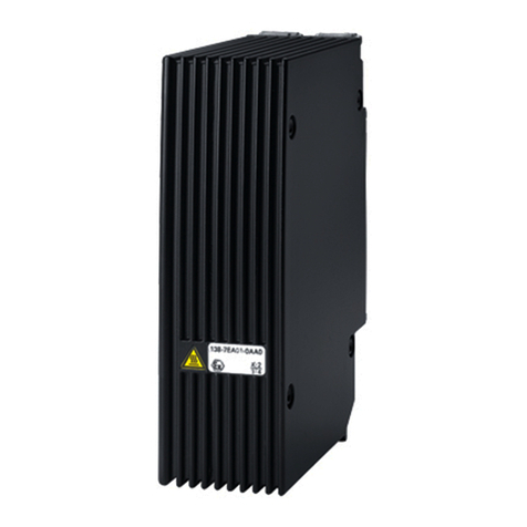
Siemens 6ES7138-7EA01-0AA0 User manual

Siemens

Siemens 6ES7138-7EA01-0AA0 User manual

Siemens PS-5A User manual

Siemens

Siemens PS-5A User manual

Siemens SITOP power 20 User manual

Siemens

Siemens SITOP power 20 User manual

Siemens MICROMASTER 430 FX Operating and maintenance instructions

Siemens

Siemens MICROMASTER 430 FX Operating and maintenance instructions

Siemens SITOP series User manual

Siemens

Siemens SITOP series User manual

Siemens PSC-12 User manual

Siemens

Siemens PSC-12 User manual

Siemens SITOP power flexi User manual

Siemens

Siemens SITOP power flexi User manual

Siemens 4AV2106-2EB00-0A User manual

Siemens

Siemens 4AV2106-2EB00-0A User manual

Siemens 4AV Series User manual

Siemens

Siemens 4AV Series User manual

Siemens SITOP PSU2600 3ph User manual

Siemens

Siemens SITOP PSU2600 3ph User manual

Siemens SINAMICS G120P PM330 Operating and maintenance instructions

Siemens

Siemens SINAMICS G120P PM330 Operating and maintenance instructions

Siemens 4AV2102-2EB00-0A User manual

Siemens

Siemens 4AV2102-2EB00-0A User manual

Siemens SITOP PSE200U 3A User manual

Siemens

Siemens SITOP PSE200U 3A User manual

Siemens SITOP series User manual

Siemens

Siemens SITOP series User manual

Siemens SITOP PSU8200 User manual

Siemens

Siemens SITOP PSU8200 User manual

Siemens LOGO!Power Series User manual

Siemens

Siemens LOGO!Power Series User manual

Siemens SITOP SEL1200 User manual

Siemens

Siemens SITOP SEL1200 User manual

Siemens SIMATIC NET PS598-1 Administrator guide

Siemens

Siemens SIMATIC NET PS598-1 Administrator guide

Siemens SITOP C98130-A1251-A1-02-19 User manual

Siemens

Siemens SITOP C98130-A1251-A1-02-19 User manual

Siemens SIMATIC ET200SP PS 6EP7133-6AB00-0BN0 24 V/5... User manual

Siemens

Siemens SIMATIC ET200SP PS 6EP7133-6AB00-0BN0 24 V/5... User manual

Siemens SITOP PSU100S User manual

Siemens

Siemens SITOP PSU100S User manual

Siemens SIMATIC PS307 User manual

Siemens

Siemens SIMATIC PS307 User manual

Siemens 5WG1125-4CB33 User manual

Siemens

Siemens 5WG1125-4CB33 User manual

Siemens SITOP PSU100L User manual

Siemens

Siemens SITOP PSU100L User manual

Popular Power Supply manuals by other brands

Omron S8VM Series Product information

Omron

Omron S8VM Series Product information

POWER ON BOARD VEC1029FPOB User's manual & warranty information

POWER ON BOARD

POWER ON BOARD VEC1029FPOB User's manual & warranty information

Moxa Technologies DRP-240 Series Hardware installation guide

Moxa Technologies

Moxa Technologies DRP-240 Series Hardware installation guide

Bentel Security BAQ15T12 quick start guide

Bentel Security

Bentel Security BAQ15T12 quick start guide

Chroma Color Block PSU30 user manual

Chroma

Chroma Color Block PSU30 user manual

Cosel LHA10F instruction manual

Cosel

Cosel LHA10F instruction manual

Puls FIEPOS FPS300.246-036-104 manual

Puls

Puls FIEPOS FPS300.246-036-104 manual

Lionel 180-Watt PowerHouse owner's manual

Lionel

Lionel 180-Watt PowerHouse owner's manual

Pulsar GREEN POWER CCTV BNC04124 quick start guide

Pulsar

Pulsar GREEN POWER CCTV BNC04124 quick start guide

PCWork PCW07B user manual

PCWork

PCWork PCW07B user manual

TeddyPardo TeddyCAP owner's manual

TeddyPardo

TeddyPardo TeddyCAP owner's manual

ZincFive UPStealth 2 user manual

ZincFive

ZincFive UPStealth 2 user manual

Valcom VP6124 datasheet

Valcom

Valcom VP6124 datasheet

3B SCIENTIFIC PHYSICS 1001011 instruction sheet

3B SCIENTIFIC PHYSICS

3B SCIENTIFIC PHYSICS 1001011 instruction sheet

Elektro-Automatik EL 9000 DT Series operating manual

Elektro-Automatik

Elektro-Automatik EL 9000 DT Series operating manual

Omron S8VK-T Series manual

Omron

Omron S8VK-T Series manual

Eaton CEAG LP-STAR Mounting and operating instructions

Eaton

Eaton CEAG LP-STAR Mounting and operating instructions

Altronix AL400ULXJG installation guide

Altronix

Altronix AL400ULXJG installation guide

manuals.online logo
manuals.online logoBrands
  • About & Mission
  • Contact us
  • Privacy Policy
  • Terms and Conditions

Copyright 2025 Manuals.Online. All Rights Reserved.