Novitec g-Nova3D User manual

Copyright ©2022_Ver.1 NOVITEC Co., Ltd.
[g-Nova3D]
[User Manual]

[g-Nova3D User Manual]
2
Copyright ©2022_Ver.1 NOVITEC Co., Ltd.
CONTENTS
1. ABOUT THIS DOCUMENT ................................................................................................................ 5
2. IMPORTANT INFORMATION............................................................................................................ 5
2.1. INSTRUMENT SAFETY INSTRUCTIONS............................................................................................................................................5
2.2. OPERATION CONSIDERATIONS.......................................................................................................................................................5
2.2.1. Important Safety Precautions.................................................................................................................................5
2.2.2. Handling and Cleaning .............................................................................................................................................5
2.2.3. Installation.......................................................................................................................................................................6
2.2.4. Performance and Longevity ....................................................................................................................................6
2.2.5. Connector........................................................................................................................................................................ 6
2.2.6. C-mount Adjustment .................................................................................................................................................6
3. CAMERA INTRODUCTION................................................................................................................ 7
4. QUICK START ...................................................................................................................................... 7
4.1. SYSTEM REQUIREMENTS .................................................................................................................................................................7
4.2. DOWNLOAD SDK............................................................................................................................................................................7
5. CAMERA INSTALLATION AND CONFIGURATION........................................................................ 7
5.1. CAMERA CONNECTION...................................................................................................................................................................7
5.1.1. POWER I/O......................................................................................................................................................................8
5.1.2. Network Cable Connection .....................................................................................................................................9
5.2. INSTALL SDK ....................................................................................................................................................................................9
5.2.1. Novitec Camera SDK File Execution....................................................................................................................9
5.2.2. Install SDK and 3D Camera Viewer, Examples ...............................................................................................9
5.3. NETWORK SETTINGS......................................................................................................................................................................10
5.3.1. Network settings in DHCP environment.........................................................................................................10
5.3.2. Set static IP ...................................................................................................................................................................10
5.4. ACCOUNT SETUP ON FIRST USE..................................................................................................................................................14
5.4.1. Camera Connect in the Novitec 3D Camera Viewer.................................................................................14
5.4.2. Create an account in Novitec 3D Camera Viewer......................................................................................14
6. TO OPERATE......................................................................................................................................15
6.1. NOVITEC 3D CAMERA VIEWER ...................................................................................................................................................15
6.1.1. Menu................................................................................................................................................................................15

[g-Nova3D User Manual]
3
Copyright ©2022_Ver.1 NOVITEC Co., Ltd.
6.1.2. Toolbar ............................................................................................................................................................................16
6.1.3. Image Display Window ...........................................................................................................................................16
6.1.4. Camera Settings Window.......................................................................................................................................16
6.1.5. Status Bar.......................................................................................................................................................................17
6.2. 2D DATA ACQUISITION.................................................................................................................................................................17
6.2.1. 2D Image Settings.....................................................................................................................................................17
6.3. PROFILE DATA ACQUISITION ........................................................................................................................................................18
6.3.1. Profile Settings ............................................................................................................................................................18
6.4. RANGEMAP DATA ACQUISITION .................................................................................................................................................18
6.4.1. RangeMap Settings...................................................................................................................................................19
6.5. 3D DATA ACQUISITION.................................................................................................................................................................19
6.6. USE IO………………………………………………………………………………………………………………………………………………….19
6.6.1. Trigger Input.................................................................................................................................................................20
6.6.2. Strobe Output..............................................................................................................................................................20
6.7. SENSOR CALIBRATION...................................................................................................................................................................20
6.7.1. Calibration Method...................................................................................................................................................20
6.8. FIRMWARE UPDATER......................................................................................................................................................................21
7. SET ...................................................................................................................................................... 22
7.1. OUTPUT MODE ...............................................................................................................................................................................22
7.1.1. 2D......................................................................................................................................................................................22
7.1.2. 2D /Profile .....................................................................................................................................................................22
7.1.3. 3D......................................................................................................................................................................................22
7.2. 3D PROFILE SETTINGS ..................................................................................................................................................................22
7.2.1. COG (Center of Gravity)..........................................................................................................................................22
7.2.2. 3D Data Type ...............................................................................................................................................................22
7.2.3. Dual Peak.......................................................................................................................................................................22
7.2.4. Frame Combine ..........................................................................................................................................................23
7.3. LINE TRIGGER..................................................................................................................................................................................23
7.4. FRAME TRIGGER .............................................................................................................................................................................23
7.5. FEATURES.........................................................................................................................................................................................23
7.5.1. Device Control.............................................................................................................................................................23
7.5.2. Action Control .............................................................................................................................................................24
7.5.3. Image Format Control .............................................................................................................................................24
7.5.4. Acquisition Control ...................................................................................................................................................24

[g-Nova3D User Manual]
4
Copyright ©2022_Ver.1 NOVITEC Co., Ltd.
7.5.5. Scan3D Control...........................................................................................................................................................25
7.5.6. Analog Control............................................................................................................................................................26
7.5.7. Digital IO Control.......................................................................................................................................................26
7.5.8. User Set Control .........................................................................................................................................................26
8. APPENDIX..........................................................................................................................................26
8.1. G -NOVA3D SPECIFICATIONS ......................................................................................................................................................26
8.2. LUXIMA LUX1310 SPECIFICATIONS ...........................................................................................................................................27
8.3. G-NOVA3D DIMENSIONS ............................................................................................................................................................28
9. IMAGE INDEX ...................................................................................................................................29
10. TABLE INDEX ..................................................................................................................................30
11. REVISION HISTORY .......................................................................................................................30
12. CONTACT.........................................................................................................................................30

[g-Nova3D User Manual]
5
Copyright ©2022_Ver.1 NOVITEC Co., Ltd.
1. About this document
This document is for those new to the g-Nova3D camera. This document introduces the basic
information required to use the camera –H/W and S/W installation and how to acquire data using the
provided viewer.
API documentation and example project for programming requirements.
For more information, please visit Novitec Technical Support Cafe.
(https://cafe.naver.com/novitecsupport)
2. Important Information
2.1. Instrument Safety Instructions
-We are not responsible for any damage caused by user negligence or other equipment connection.
-Please handle the camera with care. strong shock or please be careful when storing in an unsuitable
environment.
-Please do not use accessories that are not recommended as they may be dangerous.
2.2. Operation Considerations
2.2.1. Important Safety Precautions
-Please check the specifications for each product and use a power supply with the appropriate specifications.
-The product is a radiator, fire, stove, or other product (amplifier, etc.) Please use it away from heat sources
such as
-flammable substances, water, or be careful not to let metal get inside the camera.
-Do not modify the camera or use the camera with the outer cover removed.
-Thunder, Stop using the camera in lightning strikes.
-When using the camera outdoors, protect it from moisture. (rain / snow, etc.)
-Board level notes
◼Be careful to avoid electric shocks such as static electricity (ESD).
◆Please use grounding to respond ESD.
◆Avoid all plastic, vinyl, and Styrofoam around printed circuit boards.
◆Do not touch the components on the circuit board with your hands or conductive devices.
2.2.2. Handling and Cleaning
-Do not attempt to disassemble the camera.
-Lens and filter replacement Or, when removing, be careful not to let water or dust enter.

[g-Nova3D User Manual]
6
Copyright ©2022_Ver.1 NOVITEC Co., Ltd.
-Use a blower or lens brush to remove dust from the lens or optical filter.
-Do not disassemble the front flange.
-Clean the case with a soft, dry cloth.
-Do not use the cleaner like Benzene, thinner, alcohol, water, or spray.
2.2.3. Installation
Avoid installing or storing the camera in the following locations.
-Environments exposed to direct sunlight, rain, or snow
-Environments where combustible or corrosive gas exists
-Excessive temperature or low temperature environment (recommended ambient temperature: 0 to 45 °C)
-Wet or dusty places
-Places subject to excessive vibration or shock
-Environments exposed to strong electric or magnetic fields
-An environment where the camera is installed facing the sun or other strong light sources
-In case of unfavorable environment, be sure to inquire about the installation environment before installation.
2.2.4. Performance and Longevity
Please configure the environment that meets the camera operation specifications. If the ambient temperature is high,
the service life may be shortened due to deterioration of the parts. In that case, you also need to consider the
cooling system.
2.2.5. Connector
-I /O connector, please be careful with the connection so that the wires fit well.
-Make sure the power is off before connecting or disconnecting the I /O connector.
-To avoid damaging the connector, do not pull by holding the electric wire, etc.
2.2.6. C-mount Adjustment
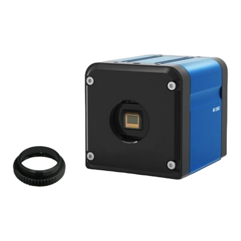
g-Nova3D is basically manufactured as a CS-mount, and a C-mount lens can be used by using the extension ring as
shown in the figure below.
<Image> 1. g-Nova3D mount (CS) and extension ring (CS to C) Image

[g-Nova3D User Manual]
7
Copyright ©2022_Ver.1 NOVITEC Co., Ltd.
3. Camera Introduction
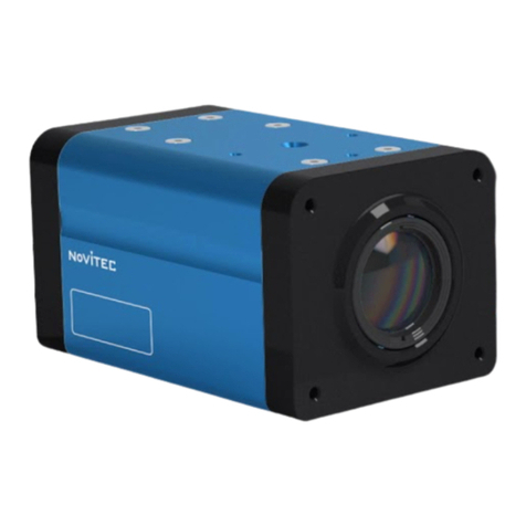
g-Nova3D is a laser triangulation method optimized for high- speed 3D inspection. High speed 3D camera.
Please refer to Chapter8 Appendix for camera specifications.
<Image> 2. g-Nova3D Camera Image
4. Quick Start
4.1. System Requirements
-OS: Microsoft Windows 7/8/10(32bit, 64bit), Linux(32bit/64bit/ARM64)
(However, Novitec Camera Viewer for Windows only supports 64bit OS.)
4.2. Download SDK
The SDK provided supports C++ and C#. (However, Linux supports only C++.)
SDK can be downloaded from our website.
(https://www.novitec.co.kr/its/sub/support03.php?category=SDK)
5. Camera Installation and Configuration
5.1. Camera Connection
On the back of the camera, there is a power I /O connector and a network connector as shown below.

[g-Nova3D User Manual]
8
Copyright ©2022_Ver.1 NOVITEC Co., Ltd.
<Image> 3. g-Nova3D Rear Port Image
5.1.1. POWER I/O
The g-Nova3D camera uses 12V power. Connect the power to the 12pin power I /O cable, Connect the power cable
to the camera.
Pin map of POWER I/O of g-Nova3D is as follows.
<Image> 4. Power I/O Pin Map Image
Pin
signal
Description
1
GND
Camera Ground
2
CAMERA POWER
Camera Power (12V)
3
STROBE OUT
Strobe Output
4
ENC IN A+
Encoder Input A+
5
ENC INA-
Encoder Input A-
6
IO POWER
IO Power
7
TRIG IN-
Frame Trigger Input
8
-
-

[g-Nova3D User Manual]
9
Copyright ©2022_Ver.1 NOVITEC Co., Ltd.
9
TRIG IN
Line Trigger Input
1 0
ENC IN B+
Encoder Input B+
1 1
ENC IN B-
Encoder Input B-
1 2
IO GND
IO Ground
<Table> 1. Power I/O Pin Map Table
5.1.2. Network Cable Connection
Network cable to the camera and PC.
When using DHCP, connect the cable to the router/switch/hub connected to the network with the camera and DHCP
server.
5.2. Install SDK
Execute the provided Novitec Camera SDK Installer to install the SDK.
5.2.1. Novitec Camera SDK File Execution
<Image> 5. Novitec Camera SDK Installation Image1
5.2.2. Install SDK and 3D Camera Viewer, Examples

[g-Nova3D User Manual]
10
Copyright ©2022_Ver.1 NOVITEC Co., Ltd.
<Image> 6. Novitec Camera SDK Installation Image2
SDK is installed by default. If necessary, you can install 3D Camera Viewer and Examples together. Click the “Next”
button to complete the SDK installation.
5.3. Network Settings
When the camera is connected at the first time, camera IP settings option is set to DHCP and LLA (Link Local
Address) by default. When the camera is failed to connect a DHCP server, the IP address is set by using LLA.
5.3.1. Network settings in DHCP environment
DHCP is set when the camera is shipped. When using for the first time, if the camera is connected to a network with
a DHCP server, no additional settings are required.
5.3.2. Set static IP
When the camera is connected to the PC directly, IP settings of the camera and PC’s network adapter are required.
5.3.2.1. PC Network Adapter IP Settings
①Open control panel and click “View network status and tasks” below “Network and Internet”

[g-Nova3D User Manual]
11
Copyright ©2022_Ver.1 NOVITEC Co., Ltd.
<Image> 7. Control Panel Image
②Click “Change adapter settings” on the left side of the screen.
<Image> 8. Control Panel –Network Status and Tasks Screen Image
③Right Click on the network to which the camera is connected and select “Properties” from the menu.
<Image> 9. Network Right Click Menu Image
④When the Ethernet properties appears, select “Internet Protocol Version 4(TCP/IPv4)”, and click
“Properties

[g-Nova3D User Manual]
12
Copyright ©2022_Ver.1 NOVITEC Co., Ltd.
<Image> 10. Ethernet Properties Screen Image
⑤In Internet Protocol Version 4(TCP/Ipv4) properties screen, click “Use the following IP address” and
then, set up IP address and subnet mask.
When using static IP, usually use private IP address class C. The C class ranges from 192.168.0.0 to
192.168.255.255.
<Image> 11. Ipv4 Settings Screen Image
5.3.2.2. Camera IP settings
①Run the Novitec 3D Camera Viewer included in the SDK.
②Run the viewer and click “Connect” button on the top menu, displayed a list of connectable cameras.
If IP band set on camera and IP band on network adapter are different, it is displayed in red as below.
When you select the camera, the “Send Force IP Command” button at the bottom is activated. Click
the button to give the camera a temporary IP.

[g-Nova3D User Manual]
13
Copyright ©2022_Ver.1 NOVITEC Co., Ltd.
<Image> 12. Novitec 3D Camera Viewer –Connect Dialog Image
③Once the camera is given a temporary IP, the red color will disappear as shown in the picture below,
click the camera and click “Connect” button to connect the camera.
<Image> 13. Novitec 3D Camera Viewer –Connect Dialog Image2
After temporary IP address is assigned, the camera can be used immediately, but when the power is
reset, IP settings are reset to default. Set up persistent IP to keep IP settings after camera is reset.
④After running the viewer and connecting the camera, click the “Configuration Persistent IP” checkbox
in the “Transport Layer Control” category of the Camera Property on the right side of the Viewer. Enter
the IP, Subnet Mask, and Gateway to set.

[g-Nova3D User Manual]
14
Copyright ©2022_Ver.1 NOVITEC Co., Ltd.
<Image> 14. Persistent IP Setting Image
The IP you enter must be the same as the IP band of the PC network adapter
Example) PC Network Adapter –IP: 192.168.0.100, Subnet: 255.255.255.0
Camera –IP: 192.168.0.128, Subnet: 255.255.255.0
5.4. Account Setup on First Use
When connecting to camera for the first time, the user must set up ID and password. If you don’t set ID and
password, video streaming is limited.
5.4.1. Camera Connect in the Novitec 3D Camera Viewer
Run Novitec 3D Camera Viewer, connect to the camera, and click the key at the bottom right of the Viewer.
<Image> 15. Novitec 3D Camera Viewer - Account Settings Image1
5.4.2. Create an account in Novitec 3D Camera Viewer

[g-Nova3D User Manual]
15
Copyright ©2022_Ver.1 NOVITEC Co., Ltd.
Enter your ID and password and click the “Create account” button to create an account.
<Image> 16. Novitec 3D Camera Viewer - Account Settings Image2
6. To Operate
6.1. Novitec 3D Camera Viewer
The Novitec 3D Camera Viewer allows you to view basic camera controls and images. The UI of Viewer is
composed as follows.
<Image> 17. Novitec 3D Camera Viewer - Main UI Image
6.1.1. Menu

[g-Nova3D User Manual]
16
Copyright ©2022_Ver.1 NOVITEC Co., Ltd.
<Image> 18. Novitec 3D Camera Viewer - Menu Image
There are 5 items as follows.
-File: save/load images and exit the program
-Tools: firmware update
-Camera Control: connect/disconnect camera, Camera control such as start and stop
-Settings: set camera properties, screen display settings, sensor calibration, etc.
-View: image display size, such as Zoom In/Out, and display status settings such as profile view and status
bar
-Help: show program information
6.1.2. Toolbar
<Image> 19. Novitec 3D Camera Viewer - Toolbar Image
The toolbar has a camera controls function that is frequently used. These include camera connection and startup
control, snapshot, output mode setting, screen setting, etc.
6.1.3. Image Display Window
<Image> 20. Novitec 3D Camera Viewer –Image Display Window Image
When the camera starts, an image appears in the image display window. Image according to the output mode, Data
is displayed in the form of RangeMap, 3D Point Cloud.
6.1.4. Camera Settings Window

[g-Nova3D User Manual]
17
Copyright ©2022_Ver.1 NOVITEC Co., Ltd.
<Image> 21. Novitec 3D Camera Viewer –Camera Settings Window Image
Set camera properties and screen display method. You can change the setting items by changing the bottom tab.
6.1.5. Status Bar
<Image> 22. Novitec 3D Camera Viewer –Status Bar Image
Displays the current camera status, such as FPS, Image Information, and camera temperature.
6.2. 2D Data Acquisition
“Start” button on the top toolbar and click the “2D” button to set the output mode to 2D. When set, the
real-time image output from the sensor is displayed in the image display window.
<Image> 23. 2D Data Acquisition Image
6.2.1. 2D Image Settings

[g-Nova3D User Manual]
18
Copyright ©2022_Ver.1 NOVITEC Co., Ltd.
2D Mode is the stage to set the image for laser profile detection.
6.2.1.1. Main 2D Parameters
-Exposure /Gain: Adjust the sensor exposure time and gain to make the laser line visible.
-R OI: Set the ROI to match the object’s inspection height. Reducing ROI increases the available FPS.
-Frame rate: Adjust the frame rate to be used during inspection.
In 2D mode, the frame rate displayed limited to 60 FPS.
6.3. Profile Data Acquisition
Click on “2D/Profile” on the top toolbar to obtain data containing 2D images and profile information.
<Image> 24. 2D/Profile Data Acquisition Image
6.3.1. Profile Settings
This step sets the detection ROI and threshold for the profile. g-Nova3D supports dual profiles. You need to set
profile used or not, ROI, and the threshold for the profile detection.
6.3.1.1. Main Profile Parameters
-Peak0 Enable: Set whether Peak0 to used or not. Peak0 is always enabled, so it is fixed as True.
-Peak0 Y Begin/End: Detection ROI for Peak0
-Peak0 Threshold: Peak0 threshold
-Peak1 Enable: Set whether Peak1 to used or not.
-Peak1 Y Begin/End: Detection ROI for Peak1
-Peak1 Threshold: Peak1 threshold
6.4. RangeMap Data Acquisition

[g-Nova3D User Manual]
19
Copyright ©2022_Ver.1 NOVITEC Co., Ltd.
Click “RangeMap” button on the top toolbar. RangeMap is data created by accumulating profile data in
chronological order
<Image> 25. RangeMap Data Acquisition Image
6.4.1. RangeMap Settings
6.4.1.1. Main RangeMap Parameter
-FrameCombine: Determines the number of Profiles to be transmitted in one frame when data is
transmitted from the camera. Frame loss can be reduced by increasing FrameCombine during high-
speed scanning.
6.5. 3D Data Acquisition
Click “3D” button on the top toolbar. 3D Data is output on the screen by converting RangeMap into point
cloud form. You can adjust the scale of point cloud data by specifying point cloud scale X/Y/Z in the “Display
Settings” tab of the camera setting window.
<Image> 26. 3D Data Acquisition Image
6.6. Use IO

[g-Nova3D User Manual]
20
Copyright ©2022_Ver.1 NOVITEC Co., Ltd.
g -Nova3D supports TTL, Encoder, Differential Encoder format trigger input and TTL format strobe output.
g- Nova3D has separate IO power, so you need to input a separate power supply when using IO. <Table>
1. Refer to Power I/O Pin Map and connect IO Power (pin6) / IO GND (pin12) and power.
6.6.1. Trigger Input
6.6.1.1. TTL Trigger Input
Connect trigger source + to TRIG_IN (pin9)
6.6.1.2. Encoder Input
Connect A/B signal output from encoder to camera IO TRIG_IN (pin9) / TRIG_IN- (pin7)
6.6.1.3. Differential Encoder input
Connect A+/A-/B+/B- output from encoder to camera IO ENC IN A+/ ENC IN A-/ ENC IN B+/ ENC IN B-
6.6.1.4. Set Camera Properties
Set trigger related parameters in the Acquisition Control category in the Camera Property window on the right
side of the viewer.
-TriggerMode –Set whether trigger to used or not.
-TriggerSource –Set the trigger source, Specifies the connected IO. (TTL / Encoder / Differential Encoder
/ Software)
-TriggerActivation –Set the trigger activation point (RisingEdge / FallingEdge)
-TriggerDivider –Specifies the trigger multiplier
-EncoderDirection –Set the encoder direction for trigger activation (A/B/AB)
6.6.2. Strobe Output
g -Nova3D supports one TTL output. Refer to Table 2 and connect to STROBE OUT (pin3) / IO GND (pin12) of
external device and camera.
6.6.2.1. Set Camera Properties
strobe related parameters in the Digital IO Control category in the Camera Property window on the right side
of the viewer.
-Line Source –Strobe Source (Off or ExposureActive)
-Line Inverter –Invert the output signal
6.7. Sensor Calibration
g -Nova3D supplies the product with basic calibration. The calibration function is prepared so that the user
can directly calibrate for special cases such as calibration deviation during distribution. function.
6.7.1. Calibration Method
①Change the Output mode to 2D by clicking the “2D” button on the tool bar of the viewer.
Table of contents
Other Novitec Digital Camera manuals
