Novitool Aero 625 User manual
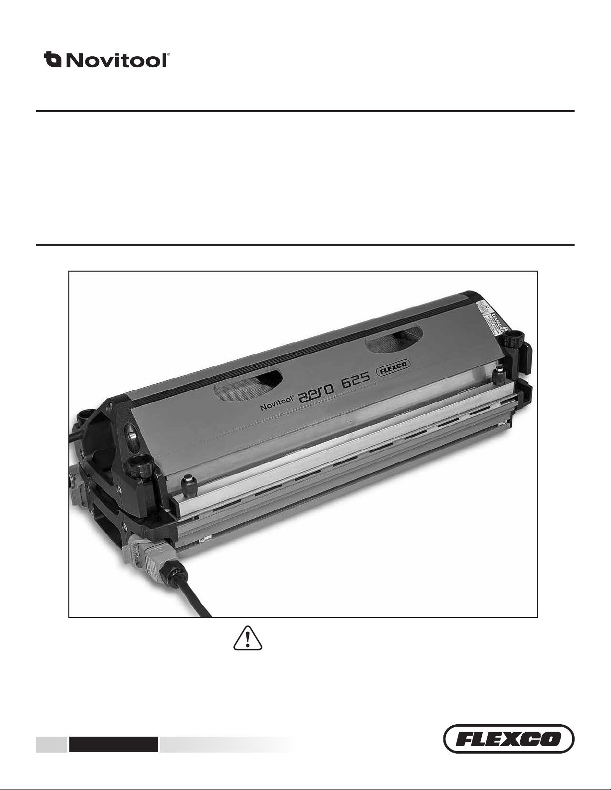
Novitool®Aero®Press
End Plate Removal Instructions
www.flexco.com
IMPROPER OR UNSAFE use of this tool can result in serious bodily injury! is manual contains important information
about product function and safety. Please read and understand this manual BEFORE operating the tool. Please keep this
manual available for other users and owners before they use the tool. is manual should be stored in a safe place.
WARNING
Patent number: US 9,090,022 B1 and other Patents Pending

www.flexco.com
—2—
Table of Contents
General Safety Rules...................................................................................... 3
End Plate Removal to Access Electrical Tray
Top Beam End Plate Removal to Access Electrical Tray ................. 5
Bottom Beam End Plate Removal to Access Electrical Tray........... 8
Electrical Tray Contents
Top Beam (Aero® 625 and 1525) Electrical Tray Contents ........... 10
Bottom Beam (Aero® 625 and 1525) Electrical Tray Contents..... 11
Reassembly of End Plate
Top Beam End Plate Reassembly...................................................... 12
Bottom Beam End Plate Reassembly ............................................... 15
Inspection Items .......................................................................................... 17
How to Clean the Platens ........................................................................... 17
Spare Parts List............................................................................................. 18
Technical Assistance ................................................................................... 18
Schematics.................................................................................................... 19
Ply 130™ply separator
—3—
Signal words:
“DANGER” indicates an imminently hazardous
situation which, if not avoided, will result in
death or serious injury. is signal word is
limited to the most extreme situations.
“WARNING” indicates a potentially hazardous
situation which, if not avoided, could result in
death or serious injury.
“CAUTION” indicates a potentially hazardous
situation which, if not avoided, may result in
minor or moderate injury. It may also be used to
alert against unsafe practices.
Safety Symbol
is international safety symbol is used to
identify and call attention to specic
safety matters.
Safety Information
To avoid severe personal injury or property
damage, read carefully and understand the
following Safety Precautions.
!
General Safety Rules – Save These Instructions
Ensure machine, power cable and power source
are not positioned in standing water or exposed
to wetconditions.
Do not connect machine to power or operate
machine if machine is wet. Machine intended
for non-condensing/non-icing conditions.
NEVER leave power cord plugged into wall
while detached from unit as this could lead to
a serious electrical danger if it comes in contact
with uids, such as water.
Service shall only be performed by
a qualied electrician. Power shall
be removed before service. Follow
Lock-Out Tag-Out procedures.
Observe proper maintenance procedures. Do
not modify electrical circuit.
1. WORK AREA
!DANGER
High Voltage!
Do not operate power tools in explosive
atmospheres, such as in the presence of ammable
liquids, gases, or dust. Power tools create sparks
which may ignite the dust or fumes.
!CAUTION
Keep your work area clean and well lit.
2. ELECTRICAL SAFETY
!DANGER
e Aero® is a single insulated machine and
needs a multiple wire grounded power cord and
grounded power supply system. Do not modify
electrical cables provided.
Never alter or remove safety devices.
Never operate press with an extension cord.
!WARNING
Operating press on incorrect voltage can cause
serious damage and potential hazards. Available
Aero® power cords:
• 110 volt; single phase
• 230 volt; single phase
• 230 volt; three phase
• 400 volt; three phase + neutral
• 400 volt; three phase
• 460 volt; three phase
Do not use outdoors. is machine is designed
for indoor use only. e press must be
transported in transport case when outdoors.
Inspect machine before each use. Ensure
machine and power cable are not damaged.
Machine shall not be operated with damaged
controllers, power cords, or other mechanical
components.

Ply 130™ply separator
www.flexco.com
—4—
!CAUTION
Only operate Aero® with machine positioned on
a level, rm surface.
NEVER use a machine which is defective or
operating abnormally. If machine appears to
be operating unusually, making strange noises,
or otherwise appears defective, stop using it
immediately and arrange for repairs.
Do not use machine if switch does not turn
it on or o. Any machine that cannot be
controlled with a switch is dangerous and must
be repaired.
Check for misalignment or binding of moving
parts, breakage of parts, and any other
condition that may aect machine operation. If
damaged, have machine serviced before using.
In order to maintain air ow, do not cover the
air inlets on top, at ends and on sides where air
ows through.
Maintain machine in clean condition. Remove
any oils, greases, or food product from outside
and inside machine.
Avoid dropping or severe handling of machine
at all times, including during movement in
transport case.
If the electrical supply cord is damaged, it must
be replaced by a special cord available from the
manufacturer or it’s service agent.
3. PERSONAL SAFETY
!WARNING
Use safety equipment. Always wear eye
protection, gloves, non-skid safety shoes, and
adhere to other safety standards of the facility
where operating the press.
Stay alert, watch what you are doing, and use
common sense when operating a machine. Do
not use machine while tired or under inuence
of drugs, alcohol, or medication. A moment of
inattention while operating machines may result
in serious personal injury.
Do not wear loose clothing or jewelry. Keep
your hair, clothing, and gloves away from
moving parts. Loose clothes, jewelry, or long
hair can be caught in moving parts.
When moving in transport case, ensure casters
are unlocked and case is latched securely.
Abide by all instructions and warning labels.
is equipment is not to be used by children
or persons with reduced physical, sensory or
mental capabilities, or lack of experience and
knowledge of the equipment.
4. USE AND CARE
!WARNING
Read and understand Aero® operations manual
before using machine.
Do not store solvents in Aero® transport case.
General Safety Rules
!CAUTION
e Aero has been optimized for process speed,
portability, and ease of use. A resulting aect
of the designed portability is that the structure
will deect as internal air pressure is increasing
during splice process. e length of press will
determine how much deection will occur at
any specic pressure. Beam extrusions were
designed with strength to return to their normal
state when pressure is relieved; deection will
not be permanent.

—5—
A
A1
Aero®Press End Plate Removal and Reassembly
Tools to Service Press
• 2 mm hex key
• 6 mm hex key
• 7 mm crescent wrench
• Aero® splice press instruction manual
A2 End Plate Removal to Access Electrical Tray
Both top and bottom press beams contain an electrical tray with all electrical and pneumatic
components. Prior to accessing electrical trays unplug all power cables (power switch alone is not
sucient). Procedure to remove electrical trays are as follows:
ÜTop Beam End Plate
Removal To Access
Electrical Tray:
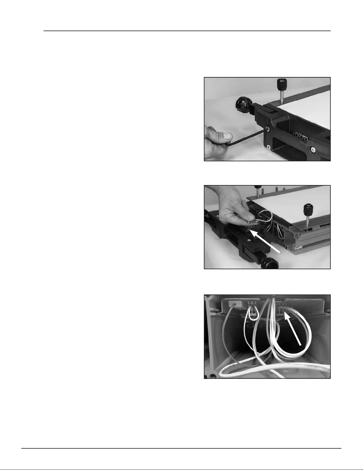
1. Locate rear top end plate (end without display
screen). Using 6 mm hex key, unscrew 3 bolts
located on rear top end plate.
Pull away from extrusion.
2. Disconnect ground wires from end plate.
Remove end plate.

Ply 130™ply separator
www.flexco.com
—6—
Top End Plate Removal
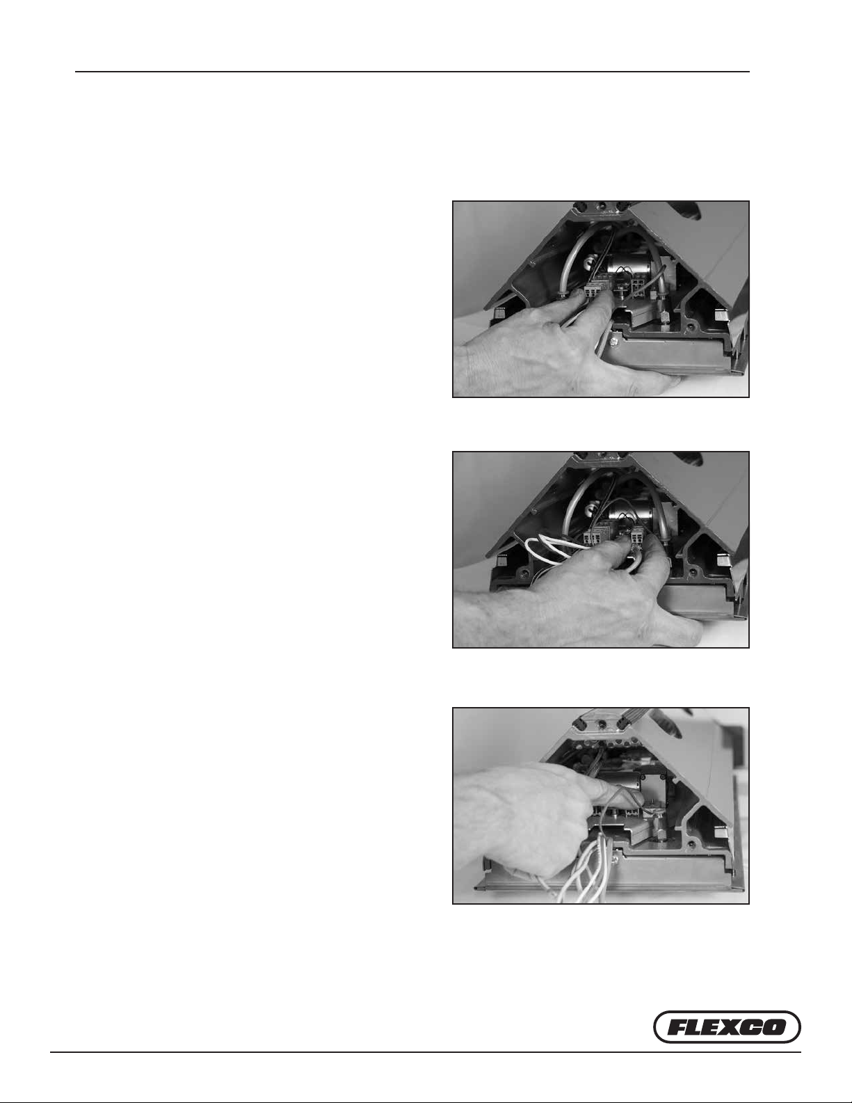
3. Disconnect by pulling three connectors straight out inside top beam of press.
NOTE: pull on connectors not wires themselves:
A. Heater connector (gray): 2 white wires
and 1 red wire
B. ermal fuse connector (gray): whitewire
C. ermocouple connector (yellow):
2 mm hex key may be used to
assist in removal

Ply 130™ply separator
—7—
Top End Plate Removal
4. Disconnect the 2 pneumatic connections.
Hold down blue ring of connector and pull
hose out.
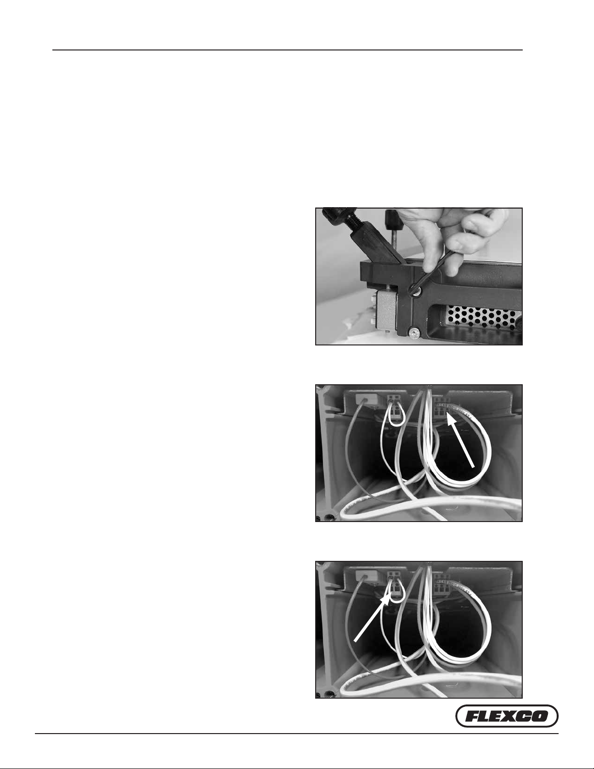
5. Using 6 mm hex key, unscrew 3 screws located
on front end plate.
Ensure wires are free to move and not tangled. en gently pull top end plate to slide electrical tray
out of beam.
Ply 130™ply separator
www.flexco.com
—8—
Bottom End Plate Removal
ÜBottom Beam End Plate Removal to Access Electrical Tray:
1. Locate rear end plate (end without electrical
connectors). Using a 6 mm hex key, unscrew 4
screws located on rear bottom end plate.
Pull away from extrusion.
2. Disconnect ground wires from end plate.
Remove end plate.
3. Disconnect by pulling three connectors
straight out inside top beam of press.
NOTE: pull on connectors not wires
themselves:
A. Heater connector (gray): 2 white wires
and 1 red wire

Ply 130™ply separator
—9—
Bottom End Plate Removal
B. ermal fuse connector (gray): whitewire
C. ermocouple connector (yellow): 2 mm
hex key may be used to assist in removal
4. Using 6 mm hex key unscrew 4 screws located
on front end plate.
Ensure wires are free to move and not tangled. en gently pull top end plate to slide electrical tray
out of beam.
Ply 130™ply separator
www.flexco.com
—10—
Electrical Tray Contents
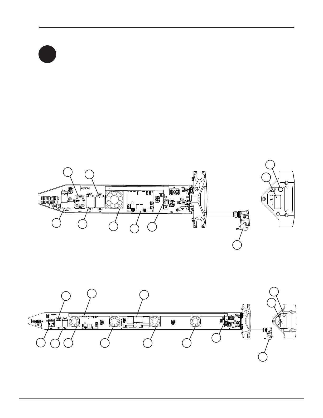
A3 Electrical Tray Contents
Top Beam Electrical Tray Contents:
A. Umbilical cable
B. Main controller with display and
control knob
C. Press release valve
D. USB connector
E. Cooling fans
F. Compressor
G. ermal fuse relay
H. Power control PCB
I. Solid state relay
J. S/P relay
F
IG
JEHD
A
B
C
Aero® 625 Top Beam Electrical Tray
Aero® 1525 Top Beam Electrical Tray
I
J
A
B
C
G
H
E
F
EED
E

Ply 130™ply separator
—11—
Electrical Tray Contents
Bottom Beam Electrical Tray Contents:
A. Power connection
B. Umbilical cable connection
C. Cooling fans
D. 24VDC power supply
E. ermal fuse relay
F. Power controller PCB
G. Solid state relay
H. S/P relay
I. Buzzer
J. Fuses
Aero® 625 Bottom Beam Electrical Tray
H
G
C
FDC
IEJ
B
A
Aero® 1525 Bottom Beam Electrical Tray
H
GF
I
E
C C
D
CC
J
A
B
C

Ply 130™ply separator
www.flexco.com
—12—
A4 Reassembly of End Plates
ÜTop Beam End Plate Reassembly:
1. Gently slide electrical tray into beam ensuring wires are free to move and not tangled
and that there is no binding. e tray should slide in with no resistance and the end
plate should t ush to the extrusion. If there is resistance, check to make sure wires
are not catching.
2. Using 6 mm hex key, screw 3 screws located
on front of end plate starting with the two
lower screws and nalizing with the top screw.
3. At rear of press re-connect the 2 pneumatic
connections. Press hose into quick connect
tting.
Top End Plate Reassembly
Ply 130™ply separator
—13—
4. Reconnect three connectors inside top beam of press:
A. Heater connector (gray): 2 white wires
and 1 red wire
B. ermal fuse connector (gray): white wire
C. ermocouple connector (yellow): brown
wire. Match prongs to same size slot
(typically + and - up).
Top End Plate Reassembly

Ply 130™ply separator
www.flexco.com
—14—
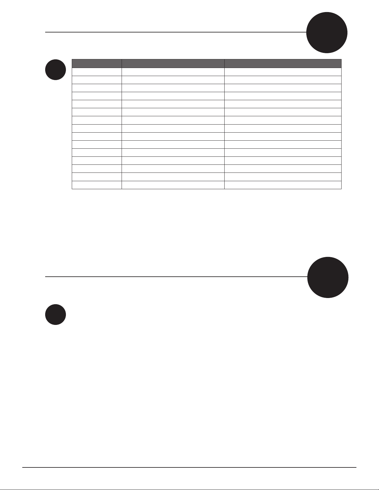
5. Reconnect ground wires to end
plate ensuring wires are oriented
to t within the extrusion prole.
Position head plate ush with the
extrusion. Place wires within slot
at end of extrusion to ensure that
the wires aren’t pinched between
the beam and the head plate. If
there is resistance a wire may be
pinched and must be adjusted.
6. Using 6 mm hex key, screw
the rear top end plate starting
with the two lower screws and
nalizing with the top screw.
Top End Plate Reassembly
Ply 130™ply separator
—15—
ÜBottom Beam End Plate Reassembly:
1. Gently slide electrical tray into beam ensuring wires are free to move and not tangled
and that there is no binding. e tray should slide in with no resistance and the
end plate should t ush to the extrusion. If there is resistance, check to make sure
wires are not catching. Check the bottom of the press to ensure that the air intake
perforated plate is not showing.
2. Using 6 mm hex key, screw 4 screws located
on front of end plate.
3. Reconnect three connectors inside bottom
beam of press:
A. Heater connector (gray): 2 white wires
and 1 red wire
B. ermal fuse connector (gray): white wire
Bottom End Plate Reassembly

Ply 130™ply separator
www.flexco.com
—16—
C. ermocouple connector
(yellow): brown wire
4. Reconnect ground wires to
end plate ensuring wires are
oriented to t within the
extrusion prole.
Position head plate ush with
the extrusion. Place wires
within slot at end of extrusion
to ensure that the wires aren’t
pinched between the beam
and the head plate. If there
is resistance a wire may be
pinched and must be adjusted.
5. Using 6 mm hex key, screw 4
screws located on rear bottom
end plate.
Bottom End Plate Reassembly

—17—
B
B1
Inspection Items
Inspection Task Every Cycle Every 100 Cycles Every 1000 Cycles
Inspect press connector bolt condition and replace if condition is
degraded. X
Inspect platen condition and clean (G2) or replace as needed. X
Inspect extrusion and head plates for any signs of fatigue. X
Inspect power connector pins for signs of arcing or wear. X
To clean the top and bottom platens, place an all-purpose cleaner on a clean cloth and wipe platens.
For area requiring further cleaning use a nylon abrasive pad.
C
C1
How to Clean the Platens
www.flexco.com
—18—
Item Code Ordering Number Description
08650 AERO-COMPRESSOR-SMALL Compressor 625-1225
08645 AERO-COMPRESSOR-LARGE Compressor 1525-2135
09249 SPRING-BAFFLE-AERO-G3-625 Spring baffle for 625
09250 SPRING-BAFFLE-AERO-G3-925 Spring baffle for 925
09251 SPRING-BAFFLE-AERO-G3-1225 Spring baffle for 1225
09252 SPRING-BAFFLE-AERO-G3-1525 Spring baffle for 1525
09253 SPRING-BAFFLE-AERO-G3-1835 Spring baffle for 1835
09254 SPRING-BAFFLE-AERO-G3-2135 Spring baffle for 2135
08604 AMIGO-FRICTION-TAPE-33X25 Tape for clamp bars
09262 BOLT-CLAMP-TOGGLE-AERO-G3 Press connector bolt
09342 T/C-SUBASSY-AERO-G3 Thermocouple
09343 FUSE-ASSY-THERMAL-AERO-G3 Thermofuse
09351 FUSE-ASSY-CERAM-FL-0326020.MSP Main power fuse 625-1225
09374 CARTRIDGE-FUSE-F-20A-RS-3375256 Main power fuse 1525-2135
08700 AERO-FUSE-CERAMIC-4A Power supply fuse/Large compressor fuse 1525-2135
Contact Flexco’s Customer Service if other parts are required: www.exco.com.
D
D1
Spare Parts List
Contact Flexco’s Customer Service if technical assistance or repair is needed: www.exco.com
E
E1
Technical Assistance

—19—
F
Schematics
Lower RS485-A
Upper RS485-A
Upper RS485-B
Lower RS485-B
V-
V-
V+
V-
Main Controller
WH
GN
BN
WH
GN
BN
07-1C
07-1C
07-1C
USB USB
RD 0,50mm²
WH 0,50mm²
06-3C
06-3C
3x 0.25mm²
3x 0.25mm²
USB Cable
06-8C
06-7C
06-7C
FLEXCO
20
15
20
15
Schematics Main Controller 625, 925, 1225, 1525, 1835, 2135

Ply 130™ply separator
www.flexco.com
—20—
Schematics Lower Press 625
Schematics
A1+
A2-
L1
T1
A1
A2
A3
A4
A3
A4
GND
1 3
5
1 23 4
5 6
Power controller Heat
05-D5
05-D5
K 1
Thermal fuse
Thermal overload relay
SSR power on/off
Serial / parrallel contact
Heating 1
24 Vdc power
1 2 3
GND
05-1A
05-1A
05-1A
B1
WH 0.50mm²
K 2
A
B
A
B
VT 2.5mm²
BU 2.5mm²
RD 0.75mm²
RD 0.50mm²
RD 0.75mm²
WH 0.75mm²
WH 0.50mm²
OG 0.50mm²
F4 20Amp
F3 20Amp
F2 20Amp
F1 20Amp
F5 4.0Amp
TB 1
BN 2.5mm²
BK 1.5mm²
BK 2.5mm²
OG 2.5mm²
GY 2.5mm²
BK 2.5mm²
BK 2.5mm²
2.5mm²
2.5mm²
2.5mm²
1.5mm²
2.5mm²
S1
05-5D05-5D
YE 1.5mm²
RD 0.75mm²
WH 0.50mm²
BU 2.5mm²
VT 2.5mm²
1
J1
P1
WH 0.75
24 Vdc
-
+
-
+
WH 0.75mm²
P8
P10
TB3
P2
SSR1
TF1
YE
BN
BK
GY
OG
WHBU 2.5mm²
DKBU 2.5mm²
DKBU 2.5mm²
DKBU 2.5mm²
GNYE 2.5 mm²
GNYE 2.5 mm²
Ground pin 1
Pin connections Omron
2 From C (DPDT)
B
A
6
5
3 4
2
1
E-Tray bottom
Ground pin 2
Bottom Headplate
backside
GNYE 2.5 mm²
LWB
supply
Splice plate
2
2
1
2
3
4
5
77
6
8
9
19
11
10
21
31
40
41
42
05-1A
05-1A
05-1A
05-1A
43
44
33
32
+
42
9
34
34
L
N
110 -240 Vac
1a
2a
10
8
18
17
16
17
18
16
15
15
13
14
13
14
45
35
12
45
35
11
10
BK 1.5mm²
OG 2.5mm²
GY 2.5mm²
7
6
24
NDR-120-24
10
2
2
36 46
19
20
21
22
20 20
21
GNYE 1.5 mm²
Q1032
B2
B1
+24Vdc
0 Vdc
+24Vdc
0 Vdc
04/1A
04/1A
04-2E
+24Vdc
WH 0.75mm²
RD 0.75mm² RD 0.75mm²
WH 0.75mm²
0 Vdc WH 0.75mm²
J1
P2
K
A
B
+
-
Thermo couple 1 Type K
Omron relay K2
Power controller heater SSR1
B5
B4
B3
WH
GN
BN
B2
B3
B4
B5
B6
WH
GY
GN
YE
BN
Buzzer
WH 0,5mm²
YE 0,5mm²
cable 6x 0,25mm²
cable 3x 0,25mm²
YE
BN
OG 0,5mm²
WH 0,5mm²
TB 4
P1
J1
VT 0,5mm²
WH 0,5mm²
V-
Input 0
Input 1
Input 2
Input 3
V-
RS485-B
RS485-A
Thermo couple +
Thermo couple -
Heater SSR +
Heater SSR -
S/P relay +
S/P relay -
Output 1
V-
Output 2
V-
V-
NC
V+
Power Controller
RD 0.75mm²
BK 0,25mm²
BK 0,25mm²
RD 0,25mm²
RD 0,25mm²
Fan M1
Fan M2
04-2E
04-2E
04-2E
44
43
33
32
44
33
-
+
45
35
46
36
39
49
23
23
23
23
23
24
24
24
Other manuals for Aero 625
1
This manual suits for next models
4
Table of contents
Other Novitool Power Tools manuals


Popular Power Tools manuals by other brands


Cleco
Cleco 20PTHD Series installation manual

Sieg
Sieg X2.7 instruction manual

Jefferson Professional Tools & Equipment
Jefferson Professional Tools & Equipment JEFPDB0750-12S user manual

MBW
MBW GP12 Operator's safety and service manual

Scheppacha
Scheppacha HP800 Original instruction manual

Parkside
Parkside PHKSA 18-Li B2 Operation manual


