Installation
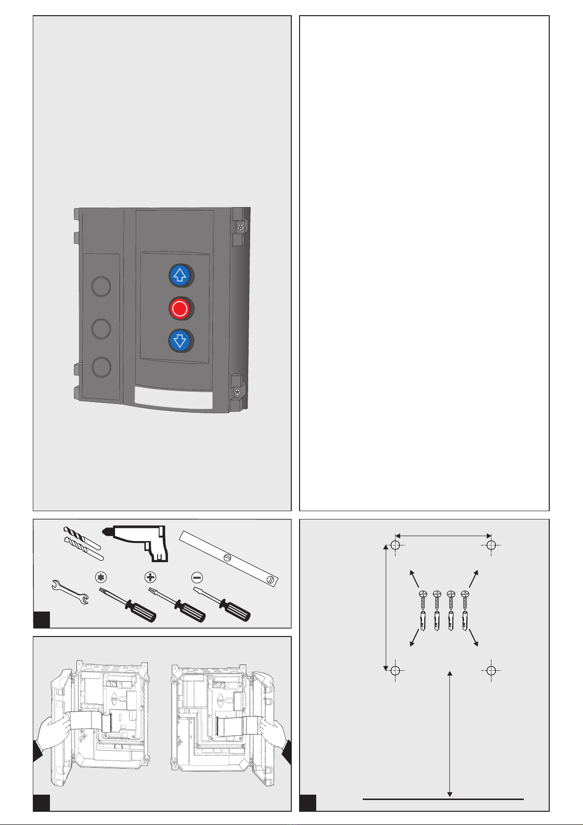
Benötigte Werkzeuge
Montage Steuerung
Öffnen der Steuerungsabdeckung
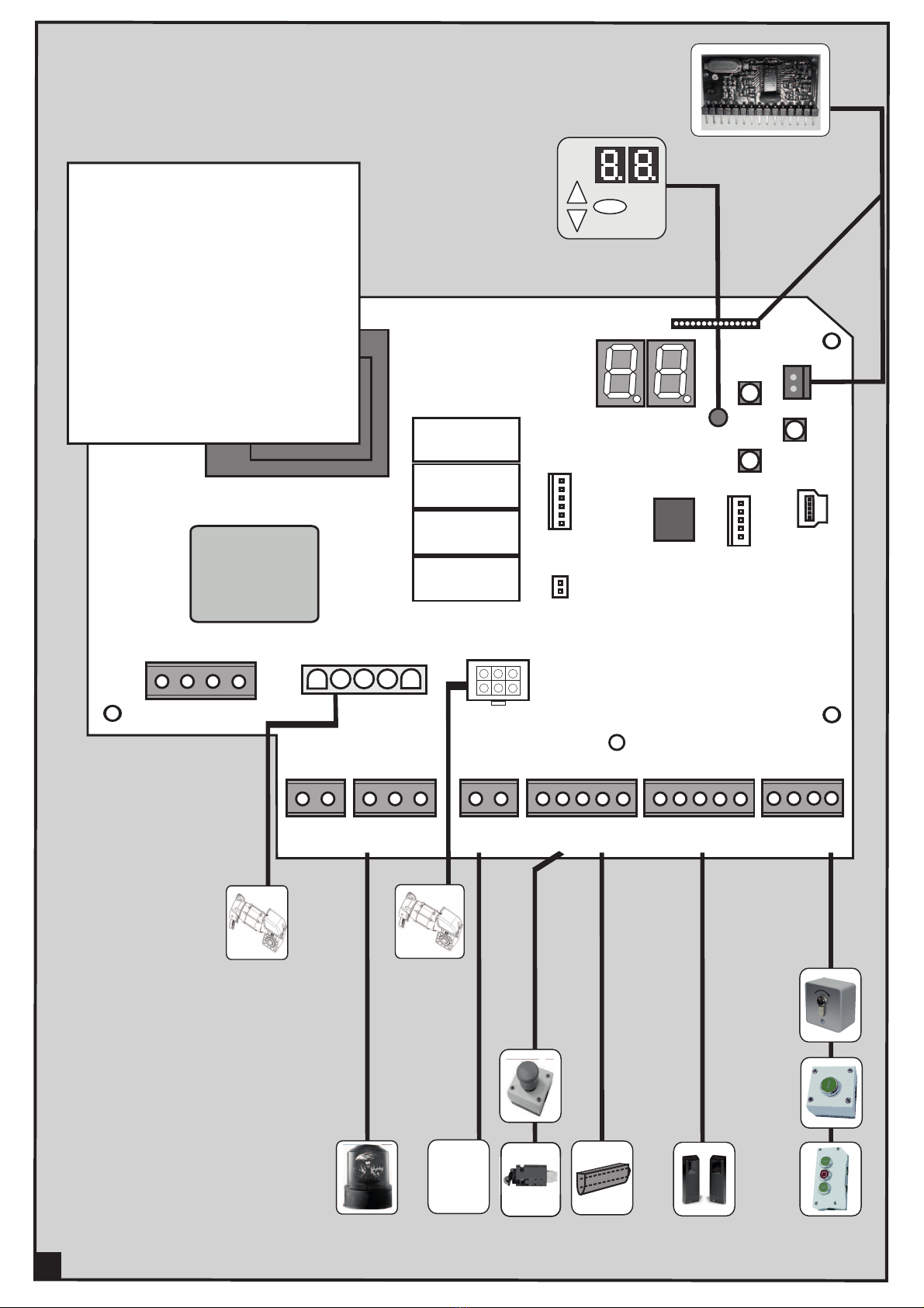
Anschlüsse
Benennung:
J1 Start / Impuls-Eingang (AUF / HALT / ZU)
J2 Sicherheitslichtschranke 2- oder 4-Draht
J3 Schließkantensicherung OSE / 8K2 / DW,
Schlaffseil, Verriegelung
J4 Antenne
J5 Aufsteck-Funkempfänger
J6 ohne Funktion
J7 ohne Funktion
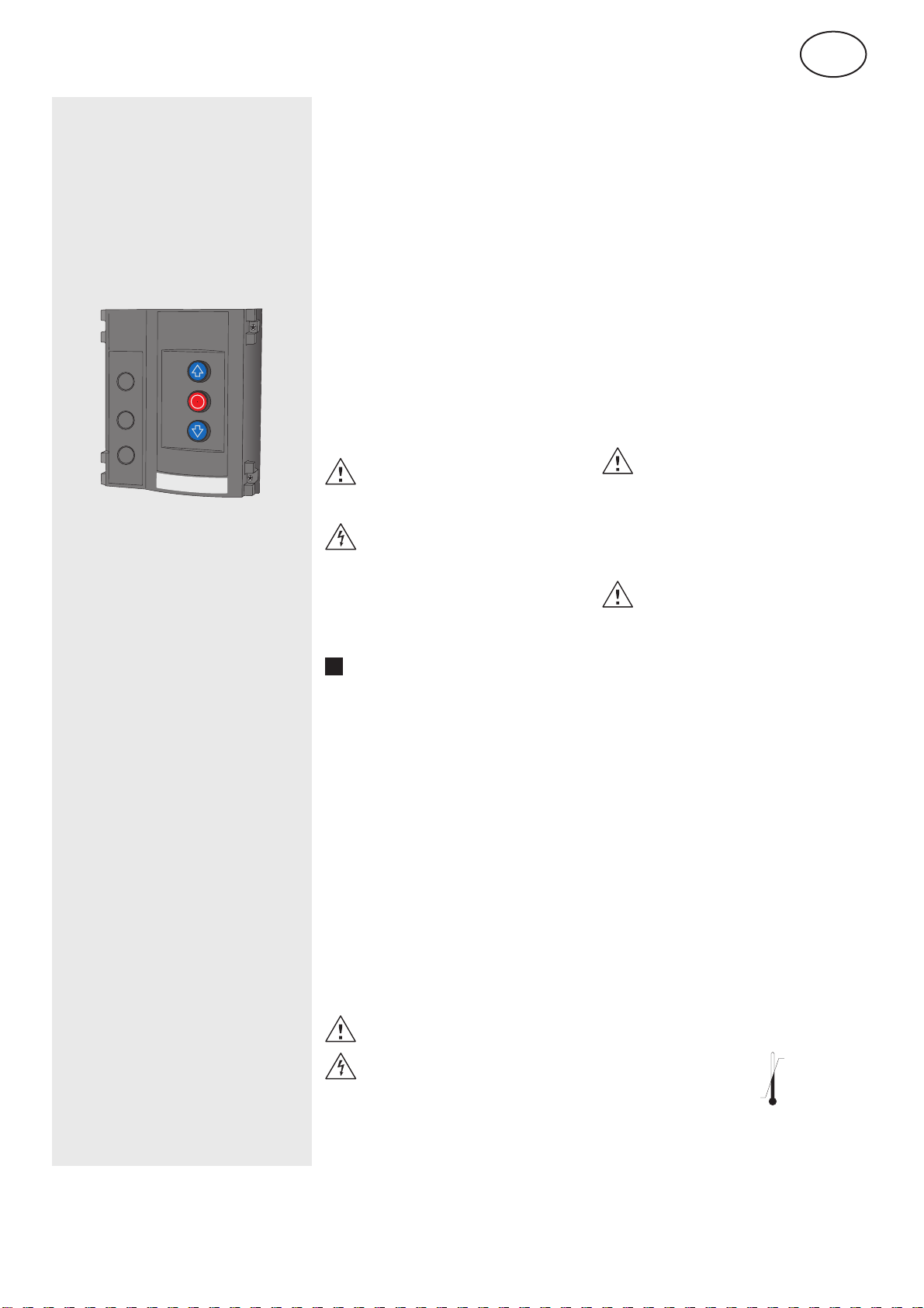
J8 Bedientasten
J9 Digitaler Endschalter - Motorkabel
J11 ohne Funktion
X1 Netzanschluss
X2 Torantrieb
X3 Potentialfreier Relais Kontakt,
Torstatusrelais
X4 24V DC, max. 150mA
Netzanschluss
Die Steuerung ist mit einem CEE-Stecker 16A und
ca. 1m Kabel anschlussfertig entsprechend 4a
verdrahtet.
Netzanschluss muss entsprechend der
vorhandenen Netzspannung ausgeführt
!werden.
Wenn die Netzleitung dieses Gerätes beschädigt
w i r d , m u s s s i e d u r c h e i n e b e s o n d e r e
Anschlussleitung ersetzt werden, die vom Hersteller
oder seinem Kundendienst erhältlich ist.
Motoranschlussleitung
Die Anschlussleitung ist für Motor und digitalen
Endschalter DES vorkonfektioniert - aufstecken.
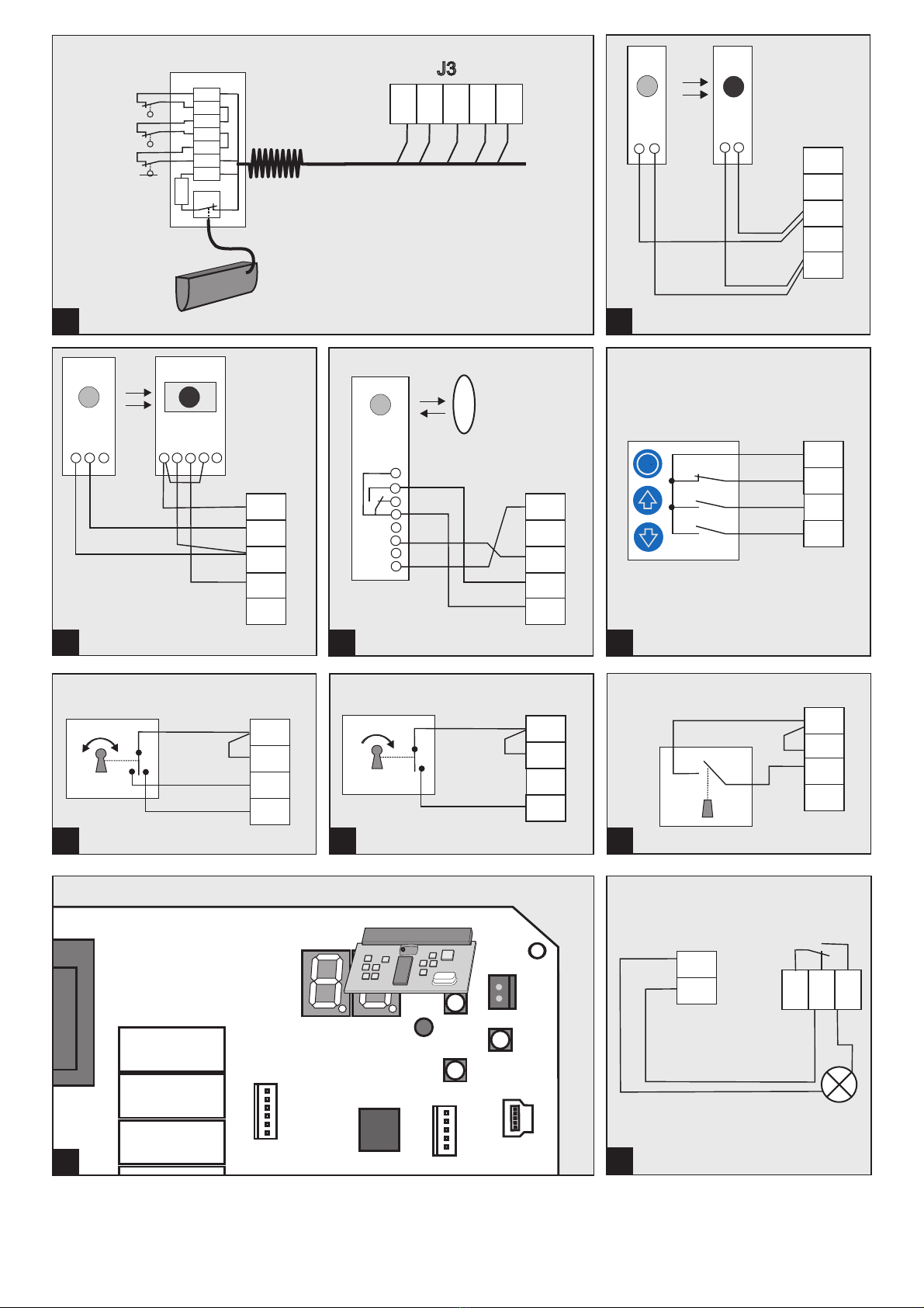
Anschluss für Schließkantensicherung
Bei Impulsbetrieb Zu ist eine Schliesskanten-
sicherung anzuschließen. Entsprechende Auswahl
im Menü 35 treffen.
6a optische Schießkantensicherung OSE (Wert =
0), elektrische Schließkantensicherung 8K2
mit 8,2 KOhm Abschlusswiderstand (Wert = 1)
6b Druckwellenleiste und -Schalter mit
8,2 KOhm Schleifenwiderstand (Wert = 2)
Anschluss für Lichtschranke
Im Menü 36 kann eine Lichtschranke entsprechend
eingestellt werden.
7a 2-Drahtlichtschranke Ls2
7b 4-Drahtlichtschranke LS5 mit Testung
7c Reflexionslichtschranke
Wenn im Menü die Lichtschranke „in der Zarge
montiert“ausgewählt wurde, führt die Steuerung bei
der nächsten Fahrt in Zu eine Lernfahrt zur
Positionserkennung durch. Diese Lernfahrt wird mit
E10 im Display signalisiert.
Dabei darf die Schließfahrt nicht gestört
werden um keine falsche Position zu
erfassen. Das Tor reversiert nicht
während dieser Lernfahrt.
Anschluss für Impulsgeber
8a Anschluss J1 für externe 3-Knopf Tasten.
Drahtbrücke J1.1/2 entfernen.
8b Anschluss J1 für Auf-Zu Schlüsselschalter.
8c/8d Schaltfolge Impuls Auf-Halt-Zu, im Menü 51
den Wert 2 einstellen.
Das Tor muss von dem Ort der
Bedienung aus einsehbar sein.
Totmann-Betrieb nur mit Schlüssel-
schalter für Zugang durch nicht einge-
wiesene Personen.
0
1
2
3
4
5
6
7
8
Funkfernsteuerung
Empfängermodul (Option) auf J5 aufstecken und im
Menü 60, 62 Handsender einlernen.
Relaisausgang
Wechslerkontakt max. belastbar: 250VAC / 2A oder
24VDC / 1A. Der 24V-Ausgang an X4 darf max. mit
150mA belastet werden. Die Relaisfunktion ist in
Menü 45 auszuwählen.
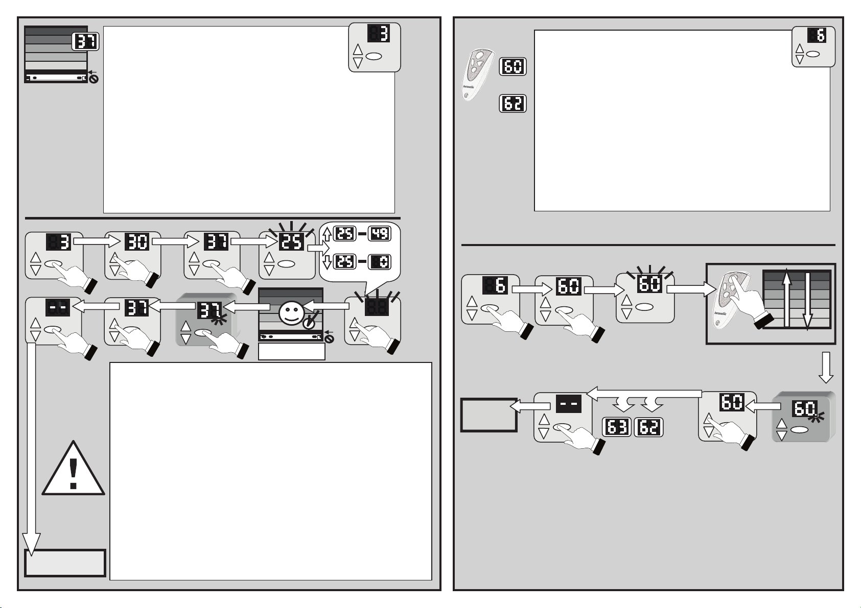
Programmieren der Steuerung
Die Programmierung ist menügesteuert.
Toreinstellung bitte entsprechend dem Schema
durchführen. Nachfolgende Seite zeigt den
kompletten Menüumfang.
Einstellen Torendlagen (Menü 30 und 31)
Abhängig vom Antrieb muss das Tor feder-
!ausgeglichen sein.
Die obere und untere Endlage müssen direkt nach
einander eingestellt werden. Die Endlagen werden in
Totmannbetrieb angefahren. Taste vor gewünschter
Endlage loslassen. Feinjustage in den Menüs 33/34
vornehmen.
Während der Fahrt ist keine Schließkanten-
oder Lichtschrankenüberwachung aktiv.
Öffnungskraftbegrenzung (Menü 48)
Die Öffnungsfahrten werden mit der vorherigen Fahrt
verglichen. Bei Überschreitung mit dem eingestellten
Wert stoppt das Tor und F33 erscheint.
Das Tor kann anschließend nur im Totmann-
betrieb zugefahren werden. Ursache der
!Kraftüberschreitung beseitigen und danach das
Tor auf und zufahren.
Motor 9.24/5.24: Eingabewert = U x Gewicht / 20 kg
Motor 14.15: Eingabewert = U x Gewicht / 15 kg
U = Wellenumdrehungen für die komplette
Toröffnung
Gewicht = Zusatzgewicht am Tor
Beispiel:
Motor 9.24, U = 8 Umdrehungen für Toröffnung
DieAbschaltung soll bei zusätzlichen 60 kg erfolgen.
Eingabewert 24= 8 x 60 kg / 20 kg =
Die Einstellung ist bei Schnellentriegelung
erforderlich, andernfalls sind Federbruch-
schalter anzuschließen.
Die Ergebnisse sind nur annäherungsweise zu
betrachten. Zur genaueren Bestimmung ist eine
Kraftmessfahrt durchzuführen.
Bei Toren, die eine Kraftbegrenzung
brauchen um der EN12453-2000,
Abschnitt 5.2.2, zu genügen, ist es
erforderlich diese Einstellung
vorzunehmen.
Die Kraftbegrenzung muss so einge-
stellt werden, dass das Mitfahren
von Personen verhindert wird.
Kontrolle der Funktion der Krafteinstellung
Nach der Kraftlernfahrt müssen die
20 kg aufgelegt werden.
Der Antrieb muss abschalten.
Einschaltdauer (Menü 49)
Die eingestellte Einschaltdauer verhindert die
Überhitzung des Antriebsmotors und vermeidet
Schäden.
Bei Einsatz des Motors 5.24 mit Kunststoff-
getriebe muss die Einschaltdauer auf 1 (3~) oder
!auf 2 (WS, 1~) eingestellt werden.
9
10
Funk Handsender einlernen
Bitte beachten Sie, dass jeder Handsender für sich
eingelernt werden muss. Sie haben die Möglichkeit
2 KeeLoq0 Funkcodes einzulernen.
Folgende Funktionen sind einlernbar.
KeeLoq, 12 Bit Multibit. Der erste Code bestimmt den
Typ.
Startimpuls (Menü 60)
Gehen sie ins Menü und betätigen Sie die Taste des
Handsenders für die Startfunktion. Sobald der Code
eingelernt ist blinkt die Punktanzeige im Display 5
mal.
Lichtfunktion (Menü 62)
Gehen sie ins Menü und betätigen Sie die Taste des
Handsenders für die Lichtfunktion. Sobald der Code
eingelernt ist blinkt die Punktanzeige im Display 5
mal.
Funkcodes löschen (Menü 63)
Zum Löschen aller eingelernter Codes im Menü ovale
Taste für 5 Sekunden gedrückt halten.