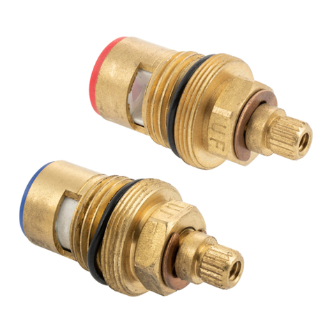
Hudson Reed A3500 Troubleshooting guide

Thermostatic
Bar Valves
Installation & operating guide
Please leave this installation & user guide with the
end user

1
CONTENTS
1. Product Variants 1
2. Important information 2
3. Cleaning & Aftercare 2
4. Box contents 3
5. Dimensions 4
6. Plumbing connections 4-5
7. Installation 5
8. Temperature adjustment 6
9. FAQ 7
1. PRODUCT VARIANTS
INS010 REV 2
Round Bar Valve with interchangeable
outlet.
Square Bar Valve with interchangeable
outlet.

2
2. IMPORTANT INFORMATION
Debris in the new pipe work can get into the cartridges. This is easily
avoided by thoroughly flushing the pipe work BEFORE connecting the
shower valve to the water supplies.
This shower valve is suitable for use with all water supply systems up
to a maximum water pressures of 5 bar (balanced water pressures
are desirable for best performance). Pressures above this limit may
require the fitting of pressure reducing valves into the incoming
mains household water supply.
This product must be installed in such a way as not to cause water
damage during use. We recommend that this product is fitted by a
fully qualified installer. The installation must comply with all
current water byelaws.
NB. If you experience any difficulty with the installation or
operation of your new shower valve, please refer to ‘FAQ’ section
at the back of this guide.
3. CLEANING & AFTER CARE
This product is made using high quality chrome plating, and this should be
maintained using a clean damp cloth. No abrasive agents or materials should
be used, and any misuse will invalidate your guarantee.
This precision made thermostatic shower valve will continue to give years of
use provided it has been installed & operated in accordance with these fitting
instructions. Failure to do this will invalidate any guarantees.

3
4. BOX CONTENTS
Note: Body, plate and outlet position may vary depending on the model supplied.
1. Main thermostatic shower valve body with built in check valves.
2. Rubber sealing washers x 2.
3. Screws and wall plug pack x 2.
4. Fast fix 15mm compression to 3/4” BSP connectors x 2.
5. Chrome wall flanges x 2.
Other items that you will require which are not supplied include (this is
not an exhaustive list): Isolation valves, Screwdrivers, Adjustable Wrench,
Bucket (for flushing out pipework), Thermometer, Silicone and a Spirit
level.
2
4
3
1
4
5
5

4
5. DIMENSIONS
ALL DIMENSIONS ARE APPROXIMATE
6. PLUMBING CONNECTIONS
The inlets will be clearly marked hot and cold. Always connect the hot
pipework to the hot side of the valve and the cold pipework to the cold side
of the valve. The pipework on site should be installed with the hot on your
left hand side and the cold on your right hand side when you face the wall.
Depending on the product, the outlet will be:
1. Top only: When installed correctly the outlet will be at the top.
2. Bottom only: When installed correctly the outlet will be at the bottom.
3. Top or bottom: The outlet is removable and can be installed on the top or
the bottom. Remove the outlet and the cap on the opposite side and
switch their positions.

5
7. INSTALLATION
1. You must install isolation valves in an accessible position on the HOT &
COLD water supply lines for servicing purposes. Check valves are already
installed in the connecting nuts.
2. Determine the fixing position for the shower valve.
3. The pipework must protrude through the wall at this fixing position.
4. Fit the water inlet pipes through the fast fix brackets, screw the brackets
to the wall and make a compression fitting with the chrome threaded nut.
5. Make sure the pipework is thoroughly flushed through to remove any
debris from the system before connecting the water supplies. Failure to
do this could invalidate the guarantee.
6. Fix the shower valve body to the connectors fitted on the wall by using the
captive nuts.
7. Make the plumbing connection to the water outlet. This will take the
water to the chosen auxiliary product (shower kit) you have selected to
run with this shower.
8. Turn on the water supply and check for leaks.
9. Turn the flow handle to the on position and turn the temperature handle
anticlockwise until it comes to a stop. Do not force it. After a few minutes,
check the temperature from the terminal outlet with a thermometer. The
recommended temperature is 42°C. If the temperature is not 42°C please
consult the temperature adjustment section.

6
8. TEMPERATURE ADJUSTMENT
9. FAQ
1. Rotate the Temperature
Handle clockwise and remove the
Cover Cap.
2. Using the 2.5mm Allen key
provided loosen the grub screw
until the Temperature Handle can
be removed.
3. The Temperature Spline Bush
will now be visible.
5. Now turn off the Shower and re-
fit the Temperature Handle back
onto the Spline Bush, making sure
that the Override Pin inside the
Handle is against the Temperature
Stop Lug on the Shower.
This will prevent the Shower from
exceeding the set temperature
unless the Override button is
pressed.
4. With the Shower running,
rotate the Temperature Spline
Bush clockwise for colder, or anti-
clockwise for hotter, until the
desired showering temperature is
achieved.
6. Making sure not to rotate the
Temperature Handle, secure it in
place with the grub screw.
7. Now replace the Cover Cap.
The Shower Valve temperature is pre-set to 42°C, but on certain installations the temperature may need to be adjusted.
Note: Ensure hot water supply is above 60°C.
Turn the Flow Control Handle to the maximum flow.
Set the temperature control knob at the 42°C position & check the temperature of the water from the outlet. If the
temperature is not set to 42°C continue below.

7
9. FAQ
ISSUE
POSSIBLE CAUSE
Temperature
issue.
(Too hot/too
cold/fluctuation)
1. Maximum temperature needs adjusting. See Temperature
Adjustment instruction.
2. Hot and cold water supplies are plumbed to the wrong sides
of the valve.
3. Check Hot Water supply temperature. (Min 60°C)
4. Operating Conditions are incorrect. (Pressure/Temperature).
5. Check the system for any blockages (pipework debris).
6. If too cold, press the Maximum Temperature Override
Button and turn the Handle to increase the temperature.
7. Water is being drawn off at other outlets or appliances.
Flow issue.
(No or poor flow)
1. Check the system for any blockages (pipework debris).
2. Operating Conditions are incorrect. (Pressure/Temperature).
3. Valve shut-off has activated due to lack of cold water supply.
4. Check that both hot and cold isolation valves are fully open.
5. Ensure that the Check-valves are not sticking.
6. Check the inlet filters for blockage.
7. For Low Pressure Systems, please ensure the header tank is
at least 1 metre above Head/Handset.
Leaking/dripping
in the OFF
position.
1. Possible debris in the CD valve.
2. Possible retained water between the Shower and
Head/Handset. (Allow several minutes for drainage).
In the unlikely event that none of the above has resolved your particular
issue please contact us on the below details.
Table of contents
Other Hudson Reed Control Unit manuals
Popular Control Unit manuals by other brands

SSV Embedded Systems
SSV Embedded Systems System-on-Module eSOM/2586 Hardware reference

Comunello
Comunello CU 230V HP Installation and user manual

Eltek
Eltek flatpack2 user manual

MG
MG R7ML-EA8 instruction manual

GEM
GEM 620 Series Installation, operating and maintenance instructions

FONESTAR
FONESTAR MSHRM-1200 quick start guide

Symmons
Symmons Showeroff 4-420 Installation and service

Dwyer Instruments
Dwyer Instruments LOVE CONTROLS 32A Series instructions

Kessel
Kessel Aqualift Mono Installation and operating instructions

Pneumax
Pneumax ENOVA 2300 Series quick start guide

LEAMING INDUSTRIES
LEAMING INDUSTRIES AGC432 Instruction book

Gefa
Gefa HGT Series operating instructions