Warner Electric • 800-825-9050 P-1177-WE • 819-0457 3
Optional Washer
A single .250 inch (6.35 mm) minimum thick steel
washer must be used between the clutch and the
crank shaft retaining bolt if the D-drive spacer is
not used.
A washer less than .250 inch
(6.35 mm) thick will deform and allow the
clamping load to be lost, resulting in damage
to the clutch and/or the crankshaft and
possible personal injury due to clutch
separating from the shaft. Multiple thinner
washers are not acceptable.
Components: (See Figure 1 on page 4.)
1. Rotor Assembly
Generally, the input of the clutch. Includes
a keyed hub which mates with the keyway
in the crank shaft. The rotor transmits the
torque from the crankshaft (driving shaft) to the
armature assembly (output).
2. Armature Assembly
Generally, the output of the clutch. Consists
of a disk, springs and pulley (or output flange).
With power applied the armature transmits
torque from the rotor to the driven load. Power
from the armature disk is transmitted to the
pulley or flange by means of the leaf springs.
3. Field Assembly
The clutch “power” source contains the coil
which generates magnetic attractive force.
4. Brake Poles
The two permanent magnets and plates ffixed
to the field shell provide the brake torque when
the clutch is disengaged. Brake poles are not
present if the assembly is a clutch only.
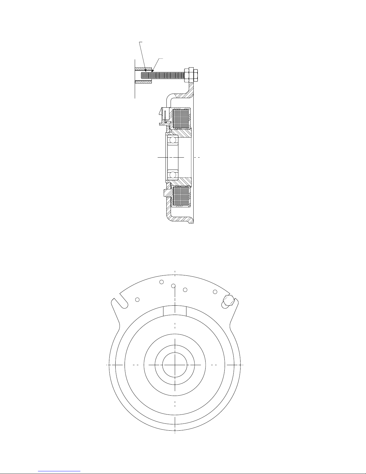
5. D-drive Spacer
A hub that is inserted into either armature or
field bearing (see Figure 2). The head has flats
that can be held with a wrench to prevent
rotation of the crankshaft when tightening
the mounting bolt (see Figure 5). This hub
also takes the place of the standard retaining
washer.
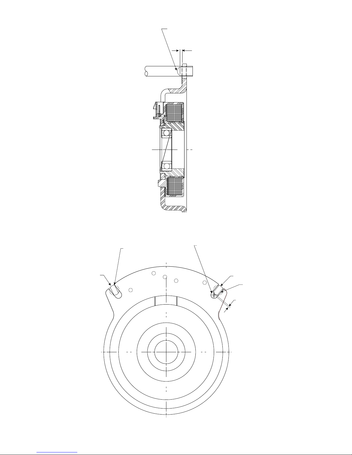
6. Anti-rotation Slot
Anti-rotation Slot (used with OEM’s anti-
rotation device) prevents MagStop from
rotation with crankshaft. If the field is bolted
rigidly or if its axial movement is restricted the
bearing in the field assembly will be improperly
loaded and may fail. Use OEM supplied anti-
rotation.
MagStop®Bearing Mounted Electric Clutch and Clutch/Brake Assemblies and Operation