Novy Up 40 00 Series User manual

NL Installatievoorschriften
FR Instructions d’installation
DE Montageanleitung
EN Installation Instructions
40 00x Novy Up
40 00X_10536_MA1

2
ALGEMENE INFORMATIE
Algemeen
Dit is de montage-instructie voor de op de voorzijde
aangegeven Novy afzuigkap. De gebruiksaanwijzing is
een apart boekje dat met het apparaat is meegeleverd.
Lees deze instructies goed door, voor de installatie en
ingebruikname van het apparaat.
In deze montage instructie wordt gewerkt met een
aantal symbolen. Hieronder vindt u de betekenis van
deze symbolen.
Symbool Betekenis Actie
Indicatie Toelichting van
een indicatie op de
afzuigkap.
Waarschuwing Dit symbool duidt op
een belangrijke tip of
een gevaarlijke situatie
Veiligheid
Neem volgende montage- en veiligheidstips in acht
voor montage:
• De installatie en de elektrische aansluiting van het
toestel dienen aan een erkende vakman toevertrouwd
te worden.
• De fabrikant kan niet verantwoordelijk gesteld
worden voor eventuele schade voortkomend uit een
foutieve inbouw of aansluiting.
• Controleer aan de hand van de tekening op pagina 4
of alle montagematerialen meegeleverd zijn.
• Het apparaat is uitsluitend bedoeld voor huishoudelijk
gebruik (bereiding van voedingsmiddelen) met
uitsluiting van alle ander huishoudelijk, commercieel
of industrieel gebruik.
• De veiligheid wordt enkel verzekerd wanneer het
apparaat volgens de vereiste voorschriften op een
aardleiding is aangesloten.
• Gebruik geen verlengkabel voor de aansluiting op
het elektrische net.
• Defecte of beschadigde onderdelen mogen alleen
door originele Novy onderdelen worden vervangen.
Belangrijk voordat u gaat monteren
Op pagina 4 van deze montage-instructie vindt u de
montage tekeningen. Voordat u gaat monteren, neem
de volgende montage tips in acht:
• Voor het eenvoudiger monteren van de afzuigkap
wordt aangeraden dit met minimaal 2 bevoegde
personen uit te voeren.
• De kast van het in te bouwen toestel is voorzien van
de juiste afmetingen.
INFORMATIONS GÉNÉRALES
Généralités
Il s’agit de la notice de montage de la hotte Novy illus-
trée en page de couverture. Le mode d’emploi consiste
en un livret distinct fourni avec l’appareil. Lisez atten-
tivement ces instructions avant d’installer et de mettre
en service l’appareil.
Ces instructions de montage font usage de quelques
symboles. Ci-dessous vous trouverez la signification
de ces symboles.
Symbole Signification Action
Indication Signification des
témoins lumineux sur
la hotte aspirante.
Avertissement Ce symbole signale
un conseil important
ou une situation
dangereuse
Sécurité
Respectez les conseils de montage et de sécurité sui-
vants pour le montage:
• L’installation ainsi que le raccordement électrique
de l’appareil doivent être confiés à un professionnel
agréé.
• Le fabricant ne peut être tenu responsable de dom-
mages éventuels, résultant d’un montage ou d’un
raccordement incorrects.
• Vérifiez, en vous référant au dessin de la page 4, si
tout le matériel de montage a été livré.
• L’appareil est uniquement destiné à l’usage domes-
tique (préparation d’aliments) à l’exclusion de tout
autre usage domestique, commercial ou industriel.
• La sécurité n’est garantie que lorsque l’appareil a été
branché à une prise de terre conformément aux les
prescriptions exigées.
• N’utilisez pas de rallonge pour le raccordement au
réseau électrique.
• Les pièces défectueuses ou endommagées ne
peuvent être remplacées que par des pièces d’ori-
gine Novy.
Important ! Avant de commencer le montage
Vous trouverez les dessins de montage en page 4 de
ces instructions de montage. Avant de commencer le
montage, suivez les conseils de montage suivants :
• Pour faciliter le montage de la hotte, il est conseillé
de procéder au moins à 2 personnes.
• Vérifiez que le meuble dispose de dimensions adap-
tées à l’appareil.

3
ALLGEMEINE INFORMATIONEN
Allgemeine Informationen
Dies ist die Montageanleitung für das auf der Vorderseite
genannte Novy Gerät. Die Gebrauchsanleitung ist
ein separates Heft, das im Lieferumfang des Geräts
enthalten ist. Lesen Sie sich diese Anleitung vor der
Installation und Inbetriebnahme des Geräts sorgfältig
durch.
Diese Montageanleitung enthält eine Reihe von
Symbolen, deren Bedeutung im Folgenden erläutert
wird.
Symbol Bedeutung Aktion
Anzeige Erläuterung einer
Anzeige.
Warnhinweis Dieses Symbol weist
auf einen wichtigen Tipp
oder eine gefährliche
Situation hin.
Sicherheit
Beachten Sie die folgenden Montage- und Sicherheits-
hinweise bei der Montage:
• Installation und elektrischer Anschluss des Geräts
sollten einem qualifizierten Fachmann überlassen
werden.
• Der Hersteller haftet nicht für Schäden, die durch
unsachgemäße Montage oder unsachgemäß
hergestellte Verbindungen entstehen.
• Kontrollieren Sie anhand der Zeichnung auf Seite 4,
ob alle Befestigungsteile mitgeliefert wurden.
• Das Gerät ist ausschließlich für den häuslichen
Gebrauch (Zubereitung von Lebensmitteln) unter
Ausschluss aller anderen häuslichen, gewerblichen
oder industriellen Nutzungen vorgesehen.
• Sicherheit ist nur gewährleistet, wenn das Gerät
gemäß den relevanten Vorschriften an eine Erdleitung
angeschlossen ist.
• Verwenden Sie kein Verlängerungskabel für den
Anschluss an das Stromnetz.
• Fehlerhafte oder beschädigte Teile dürfen nur durch
Originalteile von Novy ersetzt werden.
Wichtige vor der Montage zu beachtende Punkte
Auf Seite 4 dieser Montageanleitung finden Sie die
Montagezeichnungen. Bitte lesen Sie sich die folgenden
Hinweise durch, bevor Sie mit der Montage beginnen:
• Der Dunstabzug lässt sich einfacher montieren, wenn
mindestens zwei Personen die Arbeiten durchführen.
• Der Schrank für das einzubauende Gerät hat die
korrekten Abmessungen.
GENERAL INFORMATION
General
These are the mounting instructions for the Novy hood
shown on the cover. The user manual is a separate
booklet that is supplied with the hood. Carefully read
these instructions before installing and commissioning
the hood.
A number of symbols are used in these mounting in-
structions. The meanings of these symbols are given
below.
Symbol Meaning Action
Indication Explanation of an
indication on the hood.
Warning This symbol indicates
an important tip or a
dangerous situation
Safety
Observe the following mounting and safety tips for
mounting:
• The installation and electrical connection of the unit
shall be carried out by an authorised expert.
• The manufacturer does not accept any responsibility
for any damage resulting from faulty building in or
connection.
• Check if all mounting materials have been supplied
using the drawings on page 4.
• The unit is intended for household use only (prepara-
tion of food) excluding any other domestic, commer-
cial or industrial use.
• Safety can only be guaranteed if the unit is connect-
ed to an earth wire in accordance with the required
regulations.
• Do not use an extension cord for connecting to the
electricity grid.
• Replace defective or damaged parts only with origi-
nal Novy parts.
Important before mounting
Page 4 of these mounting instructions shows the
mounting drawings. Observe the following mounting
tips before starting the mounting activities:
• For easier mounting of the hood it is recommended
to do this with at least 2 persons.
• The housing of the unit to be mounted has the right
dimensions.

4
E
F
1
3a
E
F
ZR
S
T
3b
(B)
2
3c E F R S T Z
40 000 481 500 7 495 524 7
40 002 852 500 7 876 524 7
40 004 852 500 7 876 524 7
40 006 862 500 7 876 524 8
40 008 862 500 7 876 524 7
40 000 +
40 00 (2-8)
1354 500 7 1368 524 8
40 00 (2-8) +
40 00 (2-8)
1735 500 7 1749 524 8
(B)
(*) wok or teppanyaki always needs to be installed on the right side.
(**) Reference 40 000 always needs to be installed on the left side
(**)
(*)
(*)
(*)
(A)
(A)

5
NL - INSTALLATIE
Zorg ervoor dat het stroomcircuit waar het
apparaat op aangesloten wordt, is uitgeschakeld.
1Controleer of alle accessoires van de domino
kookplaat/kookplaten aanwezig zijn in de ver-
pakking
2Controleer of alle accessoires van de afzuigkap
aanwezig zijn in de verpakking
3a Uitsparing opbouw
Maak een uitsparing in het werkblad volgens
tabel 3c.
3b Uitsparing vlakbouw
Maak een uitsparing en een freesrand in het
werkblad volgens tabel 3c.
3c Controleer de afmetingen volgens de gekozen
installatie methode
FR - INSTALLATION
Assurez-vous que le circuit de courant auquel
l’appareil sera branché est mis hors tension
1 Vériez si tous les accessoires de la table(s) de
cuisson domino sont livrés dans l’emballage.
2 Vériez si tous les accessoires de la hotte sont
livrés dans l’emballage.
3a Pose standard
Faites une découpe dans le plan de travail,
suivant le schéma 3c.
3b Pose afeurante
Faites une découpe ainsi qu’une rainure de
fraisage dans le plan de travail, suivant le
schéma 3c
3c Vérier les dimensions en fonction de la méthode
d’installation choisie
DE - INSTALLATION
Stellen Sie sicher, dass der Stromkreis, an den
das Gerät angeschlossen wird, ausgeschaltet
ist.
1Kontrollieren Sie, dass alle Zubehörteile das
Kochfeld(er) mitgeliefert wurden.
2Kontrollieren Sie, dass alle Zubehörteile des
Geräts mitgeliefert wurden.
3a Auagemontage
Stellen Sie in der Arbeitsplatte einen Ausschnitt
entsprechend der Diagramm 3c
3b Flächenbündiger Einbau
Stellen Sie in der Arbeitsplatte einen Ausschnitt
und einen Fräsrand entsprechend der Diagramm
3c.
3c Überprüfen Sie die Abmessungen entsprechend
der gewählten Montageart.
EN - INSTALLATION
Make sure that the power circuit to which the unit
is connected is switched off.
1Check that all the domino hob(s) accessories
are present in the packaging.
2Check that all the hood accessories are present
in the packaging.
3a Surface mounting
Make a cut-away in the table top in accordance
with the table 3c.
3b Flush mounting
Make a cut-away in the table top in accordance
with the table 3c.
3c Check the dimensions according to the chosen
installation method

6
1 cm
7
10
5
89
40 006

7
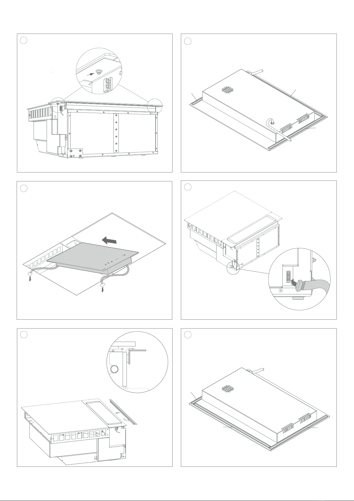
NL
4Verwijder de beschermingsfolie op de bovenkant
van de sierdekplaat.
5Druk centraal op de kantelklep van de afzuig-
toren zodat deze naar boven beweegt.
6Verwijder de beschermfolie rond de toren.
7Plaats het toestel in de voorziene uitsparing.
Plaats deze dan met het frame op 1 cm van de
rand van de uitsparing.
8Plaats de meegeleverde bocht op de uitgang
van de afzuigkap.
9Plaats de afzuigtoren mooi recht in de aanzuig-
opening van het toestel en druk deze naar
beneden via de kantelklep.
10 Enkel 40 006
Verwijder de sierdekplaat van de afzuigkap via
de 2 moeren aan de onderkant van deze plaat.
Bevestigd een extra laag meegeleverde tape (B)
aan de onderkant van de sierdekplaat.
Bevestig de sierdekplaat terug met gelijke
speling rondom de toren op de afzuigkap.
Los de 4 bouten iets aan de zijkant van de
afzuigkap en draai de stelschroef in totdat de
toren gelijk ligt met de sierdekplaat.
Zet de 4 bouten terug vast.
FR
4Retirez la feuille de protection du haut de la
plaque de recouvrement décorative.
5Appuyez au centre sur le clapet de la tour
d‘extraction pour qu’elle se déplace vers le
haut.
6Retirez le film de protection autour de la tour.
7Posez l’appareil dans la découpe prévue. Puis
placez-le avec le cadre à droite à environ 1 cm
du bord de l’évidement.
8Placez le coude fourni sur la sortie de la hotte.
9Placez la tour d’extraction bien droite dans l’ou-
verture d’aspiration de l’appareil et poussez-la
vers le bas.
10 Seulement 40 006
Retirez la plaque de recouvrement décorative
de l’appareil à l’aide des 2 écrous situés sur la
face inférieure de celle-ci.
Fixez une couche supplémentaire de ruban
adhésif fourni (B) sur sa face inférieure de
recouvrement décorative.
Fixez la à nouveau à l’appareil en respectant un
espace uniforme autour de la tour.
Desserrer légèrement les 4 boulons sur le côté
de l’appareil et serrer la vis de réglage jusqu’à
ce que la tour soit à fleur de la plaque.
Resserrez les 4 boulons.
DE
4Entfernen Sie die Schutzfolie von der Oberseite
der dekorativen Abdeckplatte.
5Drücken Sie mittig auf die Luftleitblech der
Absaugturm, damit dieser nach oben fährt.
6Entfernen Sie die Schutzfolie um den Turm.
7Stellen Sie das Gerät in die vorgesehene Aus-
sparung. Dann mit dem Rahmen rechts ca. 1 cm
vom Rand der Aussparung entfernt platzieren.
8Legen Sie den mitgelieferten 90 Grad Bogen auf
den Auslass der Dunstabzugshaube.
9Stellen Sie den Absaugturm schön gerade in
die Saugöffnung der Einheit absaugen und nach
unten drücken.
10 Nur 40 006
Entfernen Sie die dekorative Abdeckplatte mit
Hilfe der 2 Muttern an der Unterseite dieser
Platte vom Gerät.
Befestigen Sie eine zusätzliche Lage des
mitgelieferten Klebebandes (B) an der Unterseite
der Abdeckplatte.
Bringen Sie die Zierplatte mit gleichem Abstand
um den Turm herum wieder an der Einheit an.
Lösen Sie die 4 Schrauben an der Seite der
Einheit leicht und ziehen Sie die Einstellschraube
an, bis der Turm mit der Abdeckplatte bündig
ist.
Bringen Sie die 4 Schrauben wieder an.
EN
4Remove the protective foil from the top of the
decorative cover plate.
5Press centrally on the extraction tower air valve
so that it moves upwards.
6Remove the protective foil around the tower.
7Place the unit in the opening provided. Place it
with the frame on the right at about 1cm from
the edge of the recess.
8Place the supplied bend on the outlet of the
cooker hood.
9Place the extractor tower nicely straight into the
opening of the unit and push it downwards.
10 Only 40 006
Remove the decorative cover plate from the unit
using the 2 nuts on the underside of this plate.
Attach an extra layer of supplied tape (B) to the
underside of the decorative cover plate.
Attach the decorative plate back to the unit with
equal clearance around the tower.
Slightly loosen the 4 bolts on the side of the unit
and tighten the adjusting screw until the tower is
flush with the decorative plate.
Refit the 4 bolts.
8
15 40 002, 40 004, 40 006, 40 008
14
A*
A*
A*
13
12
11
B* B*
B*
16 40 002, 40 004, 40 006, 40 008

9
NL
11 Optioneel Regel de sierdekplaat bij indien deze
niet mooi uitgelijnd is rond de afzuigtoren. Los
de moeren aan de onderkant van de houders
van de sierdekplaat en regel bij. Zet de moeren
daarna opnieuw vast.
12 Bevestig de meegeleverde tape (A) aan de 3
aangeduide zijdes van de domino kookplaat
MET extra bediening (3785 of 3775).
* Enkel 40 006
Bevestig de meegeleverde tape (B) aan de 3
aangeduide zijdes van de domino kookplaat
MET extra bediening (3775).
13 Plaats de domino kookplaat (3785 of 3775)
in het frame van de afzuigkap. Verbind de
aansluitkabel en bedieningskabel doorheen de
voorziene uitsparingen van het frame.
14 Sluit de connector van de bedieningskabel aan
op de afzuigkap
15 Enkel 40 002, 40 004, 40 006, 40 008
Kleef het profiel aan de zijkant van de afzuigunit
volledige tegen de bovenkant.
16 Enkel 40 002, 40 004, 40 008
Bevestig de meegeleverde tape (B) aan de 3
aangeduide zijdes van de domino kookplaat
ZONDER bediening.
* Enkel 40 006
Bevestig de meegeleverde tape (A) aan de 3
aangeduide zijdes van de domino teppan-yaki.
FR
11 Facultatif Ajustez la plaque de recouvrement
décorative si elle n’est pas bien alignée autour
de la tour d’extraction. Desserrez les écrous sur
la face inférieure des supports de la plaque dé-
corative et ajustez. Puis resserrez les écrous.
12 Fixez le ruban adhésif (A) sur les 3 côtés mar-
qués de la table de cuisson Domino AVEC une
commande supplémentaire (3785 ou 3775).
* Seulement 40 006
Fixez le ruban adhésif (B) sur les 3 côtés
marqués de la table de cuisson Domino AVEC
une commande supplémentaire (3775).
13 Placez la plaque de cuisson domino (3785 ou
3775) dans le cadre du boîtier. Raccordez le
câble de raccordement et le câble de com-
mande à travers les évidements du cadre.
14 Raccordez à la hotte le connecteur provenant
de la table de cuisson.
15 Seulement 40 002, 40 004, 40 006, 40 008
Collez complètement le profilé sur le côté de
l’unité d’aspiration sur le dessus X = 0 mm
16 Seulement 40 002, 40 004, 40 008
Fixez la bande adhésive (B) fournie sur les 3
côtés marqués de la table de cuisson domino
SANS commande.
* Seulement 40 006
Fixez la bande adhésive (A) fournie sur les 3
côtés marqués de la table de cuisson domino
teppan-yaki.
DE
11 Optional Stellen Sie die dekorative Abdeck-
platte ein, wenn sie nicht schön um den
Extraktionsturm herum ausgerichtet ist.
Lösen Sie die Muttern an der Unterseite der
Halterungen der Zierplatte und stellen Sie diese
ein. Ziehen Sie dann die Muttern wieder fest.
12 Befestigen Sie das mitgelieferte Klebeband (A)
an den 3 markierten Seiten des Domino-Koch-
fläche MIT zusätzlicher Steuerung (3785 oder
3775).
* Nur 40 006
Befestigen Sie das mitgelieferte Klebeband
(B) an den 3 markierten Seiten des Domino-
Kochfläche MIT zusätzlicher Steuerung (3775).
13 Setzen Sie das Dominokochfeld (3785 oder
3775) in den Gehäuserahmen ein. Verbinden Sie
das Anschlusskabel und das Steuerkabel durch
die Aussparungen des Rahmens.
14 Verbinden Sie den Stecker mit der Dunstab-
zugshaube.
15 Nur 40 002, 40 004, 40 006, 40 008
Kleben Sie das Profil auf der Seite der
Absauganlage vollständig nach oben X = 0 mm
16 Einzel 40 002, 40 004, 40 008
Befestigen Sie das mitgelieferte Klebeband
(B) an den 3 markierten Seiten der Domino-
Kochfläche OHNE Bedienung.
* Nur 40 006
Befestigen Sie das mitgelieferte Klebeband (A)
an den 3 markierten Seiten der Teppan-yaki
Domino.
EN
11 Optional Adjust the decorative cover plate if it
is not nicely aligned around the extraction tower.
Loosen the nuts on the underside of the holders
of the decorative plate and adjust. Then tighten
the nuts again.
12 Attach the supplied tape (A) to the 3 marked
sides of the domino cooktop WITH additional
control (3785 or 3775).
* 40 006 only
Attach the supplied tape (B) to the 3 marked
sides of the domino cooktop WITH additional
control (3775).
13 Place the domino hob (3785 or 3775) in the hou-
sing frame. Connect the connecting cable and
control cable in the provided recesses of the
frame.
14 Connect the connector trough the cooker hood.
15 40 002, 40 004, 40 006, 40 008 only
Glue the profile on the side of the extraction unit
completely to the top X = 0 mm
16 40 002, 40 004, 40 008 only
Attach the supplied tape (B) to the 3 marked
sides of the domino cooktop WITHOUT
additional control.
* 40 006 only
Attach the supplied tape (A) to the 3 marked
sides of the teppan-yaki domino.
10
L
BN
BU
GN/YE
N
220-240V
220-240V 1N ~
21
19 20
18
22
17 40 002, 40 004, 40 006, 40 008

11
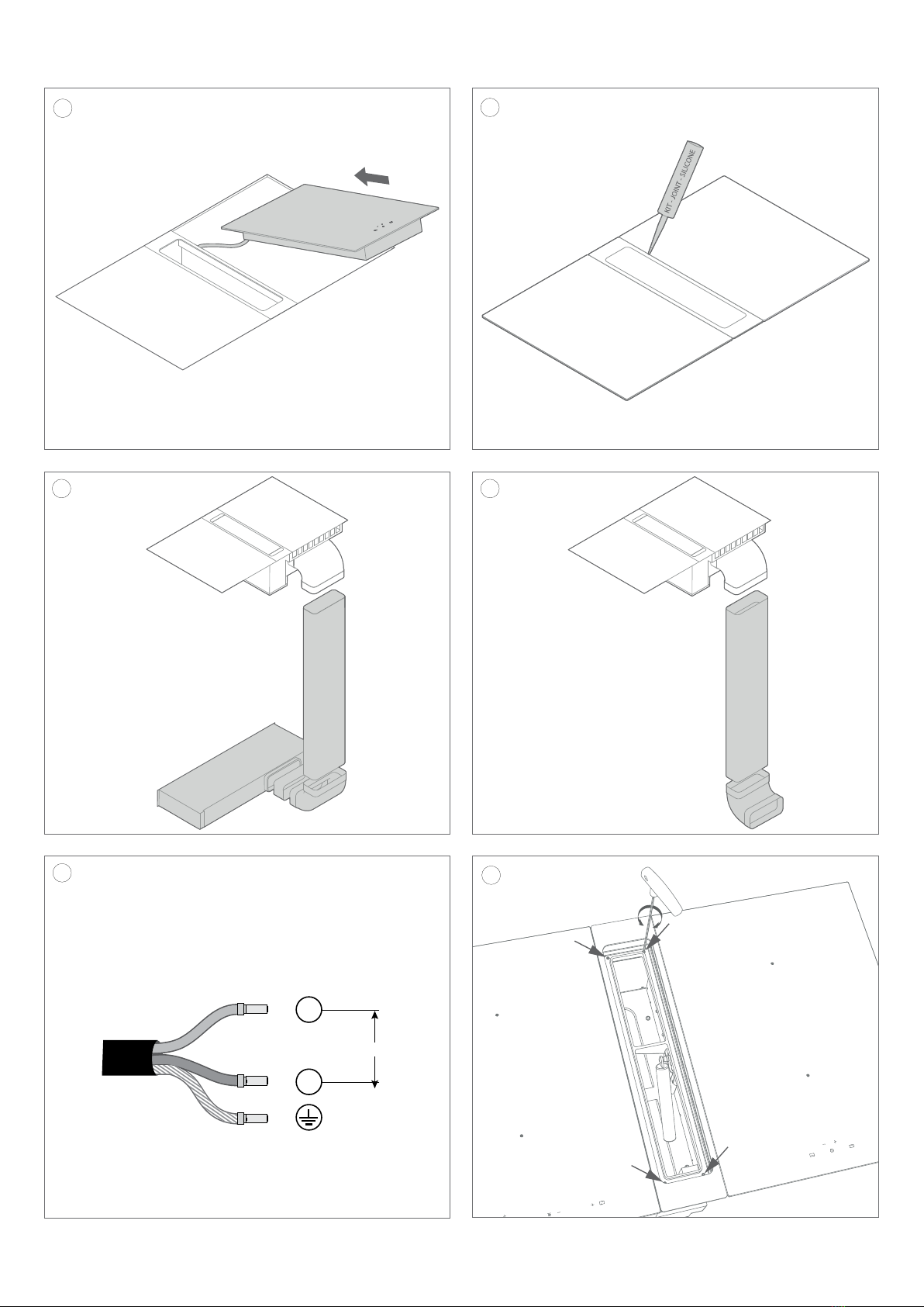
NL
17 Plaats de domino kookplaat dan rechts van de
afzuigkap.
18 Kit indien gewenst de opening tussen de domino
kookplaat en sierdekplaat rond de afzuigtoren
af.
19 Optie recirculatie inbouwbox: sluit de
inbouwbox aan op de uitgang van de afzuigkap,
maak indien nodig gebruik van optionele
hulpstukken.
20 Optie afvoer: maak gebruik van optionele
hulpstukken om de aansluiting met het
kanaalwerk naar buiten mogelijk te maken.
21 De installatie en de aansluiting op het
elektrische net mag enkel toevertrouwd
worden aan een vakman (elektricien) die
op de hoogte is van de voorgeschreven
normen.
Elektrische aansluiting Domino kookplaat
Verbind de draden Bruin (BN), Blauw (BU) en
Groen-geel (GN/YE) aan op een afgezekerde
aansluitdoos.
Elektrische aansluiting afzuigkap
Verbind de stekker op een stopcontact.
22 Aligneer indien nodig de toren met de 4 stel-
schroeven in het liftsysteem
FR
17 Placez la table de cuisson Domino à droite de la
hotte.
18 Au besoin, comblez l’espace entre la table de
cuisson Domino et la plaque décorative autour
de la tour d’extraction.
19 Caisson de recyclage à encastrer: raccordez
le caisson de recyclage à la sortie de la hotte
à l’aide des accessoires de raccordement
disponibles en option.
20 Option évacuation: Utilisez les accessoires
disponibles en option afin de raccorder la hotte
à l’évacuation extérieure.
21 L’installation et le raccordement au réseau
électrique ne doivent être confiés qu’à
un spécialiste (électricien) qui connaît les
normes prescrites.
Raccordement électrique Plaque de cuisson
Domino
Raccordez les fils Brun (BN), Bleu (BU) et Vert-
Jaune (GN/YE) à une boîte de jonction à fusibles.
Raccordement électrique hotte aspirante
Brancher la fiche à une prise électrique.
22 Si nécessaire, alignez la tour avec les 4 vis de
réglage du système de levage.
DE
17 Platzieren Sie das Domino-Kochfeld rechts
neben der Dunstabzugshaube.
18 Bei Bedarf den Spalt zwischen der Domino-
Kochfläche und die Zierplatte um den Absaug-
turm herum abdichten.
19 Option Umluft-Einbaubox: Schließen Sie die
Einbaubox an den Ausgang des Dunstabzugs
an. Verwenden Sie hierfür ggf. die optionalen
Hilfsstücke.
20 Option Ableitung mit Wandabluftgitter: Ver-
wenden Sie die optionalen Hilfsstücke, um ein-
en Anschluss an das Kanalsystem zur Ableitung
ins Freie möglich zu machen.
21 Die Installation und der Anschluss an die
elektrische Anlage darf nur von einem
Fachmann (Elektriker) durchgeführt
werden, der mit den vorgeschriebenen
Normen vertraut ist.
Elektrischer Anschluss Domino-Kochfeld
Verbinden Sie die Kabel Braun (BN), Blau (BU)
und Grün-Gelb (GN/YE) mit einem abgesicherten
Anschlusskasten.
Elektrischer Anschluss Dunstabzugshaube
Schließen Sie den Stecker an eine Steckdose
an.
22 Richten Sie den Turm bei Bedarf mit den 4
Einstellschrauben im Hebesystem aus.
EN
17 Place the domino cooktop to the right of the
cooktop hood.
18 If required, seal the gap between the domino
cooktop and the decorative plate around the
extraction tower.
19 Recirculation built-in box option: connect the
in-built box to the hood outlet, if necessary, use
optional fittings.
20 Outlet with wall outlet grille option: use
optional fittings to make the connection with the
duct work possible
21 The installation and connection to the
electrical system may only be entrusted
to a specialist (electrician) who is familiar
with the prescribed standards.
Electrical connection Domino hob
Connect the wires Brown (BN), Blue (BU) and
Green-yellow (GN/YE) to a fused junction box.
Electrical connection extractor hood
Connect the plug to an electrical outlet.
22 If necessary, align the tower with the 4 adjusting
screws in the lift system.

NOVY nv behoudt zich het recht voor te allen tijde en zonder voorbehoud de constructie en de prijzen van haar producten te wijzigen.
NOVY SA se réserve le droit de modifier en tout temps et sans préavis la construction et les prix de ses produits.
NOVY nv behält sich das Recht vor, jederzeit und ohne Vorbehalt die Konstruktion und die Preise seiner Produkte zu ändern.
Novy nv reserves the right at any time and without reservation to change the structure and the prices of its products.
NOVY nv
Noordlaan 6
B - 8520 KUURNE
Tel. 056/36.51.00 - Fax 056/35.32.51
E-mail : novy@novy.be
http://www.novy.be
France: Tél: 0320.940662
Deutschland und Österreich: Tel: +49 (0)511.54.20.771
Nederland: Tel.: +31 (0)88-0119110
España: Tel.: +34 938 700 895
Italia: Tel.: +39 039.20.57.501
Other manuals for Up 40 00 Series
1
This manual suits for next models
13
Table of contents
Other Novy Ventilation Hood manuals


Popular Ventilation Hood manuals by other brands


LG
LG SHD3689BD Service manual

arietta
arietta AAR428SSA Installation instruction guide

Swegon
Swegon casa tango Installation instruction

Gaggenau
Gaggenau AH360120 Operating and assembly instruction

NEFF
NEFF D49PU54X1 User manual and installation instructions

Küppersbusch
Küppersbusch IKD 937.0 GE Instruction booklet


