nox-crete PFCS 3615 FN User manual


2
6393250
Spare Parts
Piezas de repuesto
Pièces de Rechange
Ersatzteile

3
Ref
Part #
!
Ref
Part #
A
Air pump, brass
23
Filter housing R.25 in., brass
B
Piston rod assembly
24
100 mesh filter
C
Transport cart
25
Gasket D23 x D18 x 2 mm
D
Air compressor fill valve
26
Screw M3 x 12 mm
E
Carrying strap
27
Hex. Nut M3
F
Pressure regulator, brass with
pressure gauge
28
Trigger
G
Spiral hose with couplings
29
Valve body, brass
H
Trigger valve
30
Valve pin assembly
I
Service Kit
31
Screw seat
1
Piston rod with handle
32
Brass spray wand
2
Bumper spring
33
Buckle
3
Screw D3.5 x 16 mm
34
Wand extension ( 24 in. 61 cm)
4
Cylinder cap
35
200 mesh anti-siphon filter *
5
Piston 38 mm
36
Cap nut, brass
6
Piston cup washer 38 mm
37
80005 Spray tip
7
Safety valve 6 bar with gasket
38
800067 Spray tip
8
Gasket D14 x D9.7 x 2 mm
39
8001LP Spray tip
9
Funnel cover
40
8002LP Spray tip
10
Cylinder tube with gasket and
valve disk
41
8003LP Spray tip
11
O-ring D47 x 5.33 mm
42
8004LP Spray tip
12
Foot valve disk
43
8005LP Spray tip
13
Pressure gauge 6 bar w/ gasket
44
Holding rod
14
Pump holder with screw
45
Assembly kit for transport trolley
15
Spare parts container with lid
46
Holding rod attachment
16
O-ring D10 x 3 mm
47
Hubcap
17
Coupling M10 (spiral hose),
with gasket
48
Wheel
18
Cap nut, brass
49
Axle for transport trolley
50
Stand
20
Spiral hose 2.5 m (PUR)
51
Protective cup
21
.25 in. adapter
52
Gasket D17 x D13 x 2 mm
22
Gasket D15 x D11 x 2 mm
53
Stainless Steel Tank
4

5
6

7
USA
IRL
AUS
GB
NZ
CDN
IND
Welcome
Congratulations for purchasing your new Perfect Form and Concrete Sprayer. Your
satisfaction with NOX-CRETE products and services is very important to us. If you are not
satisfied or have questions and concerns not covered in these instructions, please contact
Nox-Crete at:
Nox-Crete Products Group
(800) 669-2738| 1444 S 20th St. | Omaha, NE | 68108 | customerservice@nox-crete.com
Read these instructions before using the sprayer.
Keep the use instructions in a safe and convenient place.
Usage
This sprayer is designed for NOX-CRETE products and other construction chemicals that
can be applied with a sprayer.
Read Nox-Crete’s sprayer usage instructions before each application. This sprayer is
designed only for use in exterior applications.
Improper use may result in personal injury.
Not suitable for
• Flammable liquids with a flashpoint below 100°F (38°C)
• Hydrogen peroxide or other strong oxidizers
• Corrosive substances (acids and bases)
• Products containing ammonia
• Products containing acetone
• Extremely viscous liquids
• Use with food
Under no circumstances should you use
• External pressure sources without the optional NOX-CRETE compressed air valve
• With flammable liquids
• For storing hazardous substances
• As an eyewash
Safety
Read sprayer instruction manual thoroughly prior to use.
Keep sprayer out of reach of children.
Never spray on people, animals, electrical devices and lines, into the wind, or into
bodies of water.
Repairs and modifications to the sprayer tank can result in serious injury.
Do not bypass or disable the sprayer safety valve.

8
USA
IRL
AUS
GB
NZ
CDN
IND
Contact between the sprayer and hydrogen peroxide or other oxidizing agents may
result in increased pressure similar to an explosion. Never place strong oxidizing
agents in the sprayer.
Remove and replace damaged and nonfunctioning parts.
Avoid ignition sources when spraying combustible liquids.
Do not allow the sprayer to remain under pressure and/or be exposed directly to
sunlight for extended periods of time. Make certain the sprayer is not heated beyond
the maximum operating temperature (→Table 1 below).
Never blow through the sprayer tip or valves with your mouth.
Use only Nox-Crete replacement and accessory parts.
Wear suitable protective equipment when working with hazardous substances.
When hand pumping or filling sprayer tank with compressed air, always observe the
pressure gauge to ensure the maximum spraying pressure is not exceeded.
(→Table 1 below).
Before filling, after use and before maintenance work, allow the residual pressure in
the tank to dissipate completely (→Section “After Use,“ Section 1).
Technical data
TABLE 1
Device Name
PERFECT Form and Concrete Sprayer
Type
Pressurized Tank
Max. usable volume
2.7 gal (10.2 l)
Total volume
3.4 gal (12.9 l)
Max. spraying pressure
87 psi (6 bar)
Max. operating temperature
122 °F (50°C)
Weight when empty
10.4 lb (4.7 kg)
Material of tank
Stainless steel
Where device is carried
Shoulder or backpack
Technical residual quantity
0.008 gal (0.03 l)

9
USA
IRL
AUS
GB
NZ
CDN
IND
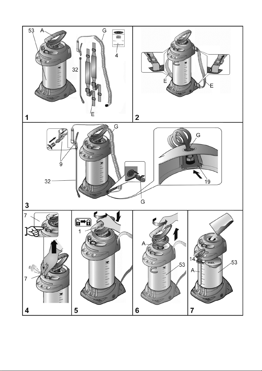
Refer to the illustrations on pages 4-6 for the following instructions.
Assembly
1. Fasten the carrying strap(s) [E] on the tank [53]. (Fig. 2)
2. Screw the hose [G] tightly into the tank outlet port. (Fig. 3).
Note the location of the spigot in order to be able to insert the lock.
3. Insert the lock [19]. (Fig. 3)
►The lock closes and the hose is secured from unscrewing out of the tank.
4. Screw the spray wand [32] onto the trigger valve [H]. (Fig. 3)
Checks
Visual inspection: Are the tank [53], pump [A], hose [G] with trigger valve [H], pressure
gauge [F] and spray wand [32] undamaged? (Figs. 1, 10, 11)
Pay special attention to the connections between the tank – hose and the hose –
trigger valve and to the condition of the pump threading and hose.
No leaks: Pump up the empty device to 30 PSI (2.1 bar).
►The pressure must not decrease more than 7 PSI (.5 bar) within 30 minutes.
Function: Pull the red button on the safety valve [7]. (Fig. 4).
►The pressure must dissipate.
Activate the trigger valve [H] (Fig. 13).
►The trigger valve must open and close.
Sprayer Preparations
Observe the instructions in the section entitled “Safety”.
1. Pull up the red button on the safety valve [7] until all excess pressure is released from
the tank. (Fig. 4).
2. Press the pump handle [1] down and turn it counterclockwise.
3. The pump handle is locked in place. (Fig. 5).
4. Unscrew the pump [A] from the tank [53]. (Fig. 6).
To ensure the pump remains clean during storage, we recommend you attach the
pump to the pump holder [14]. (Fig. 7)
5. Pour the liquid to be sprayed into the tank. (Fig. 7)
6. Screw the pump [A] into the tank [53]. (Fig. 8)
7. Swivel in the pump holder [14]. (Fig. 8)
Pressurizing with manual Pump
1. Press the pump handle [1] down and turn it clockwise.
►The pump handle is unlocked. (Fig. 9).
2. Manually pump until the required pressure is generated. (→Table 2) in the tank [53]
(Fig. 10).
The maximum pressure should not exceed 90 PSI (red line on the pressure gauge
[13], Fig. 10). If the maximum pressure is exceeded, the safety valve will engage
and release the excess pressure.

10
USA
IRL
AUS
GB
NZ
CDN
IND
3. Press the pump handle [1] down and turn it counterclockwise.
►The pump handle is locked in place. (Fig. 5).
Pressurizing with an air compressor / external pressure source
1. Connect the compressed-air hose to the compressed-air filling valve [D]. (Fig. 11).
►Pressurize to the desired pressure - maximum pressure 87 PSI (6 bar).
Ensure that the pressure of your air compressor is regulated to a maximum of 87 PSI
(6 bar).
Spraying
Observe the instructions in the section entitled “Safety”.
Operate the sprayer only while it is vertical or suspended upright and nearly vertical.
Avoid allowing drops of spray to drift onto areas not being treated.
Review the product to be sprayed health and safety warnings.
1. Carry the sprayer in your hand or place it on your back. (Fig. 12)
►To prevent dripping, purge the sprayer by holding the spray wand in the air
before spraying and open the trigger valve until no liquid mixed with air is
released.
2. Begin spraying.
Table 2
Spray Tip Recommendation Guide
Products
Recommended Spray Tip
Cures and Sealers
8003LP, 8004LP or 8005LP
Water Repellant Sealers
8003LP, 8004LP or 8005LP
Form Release Agents
Chembeton & Pro Release
8003LP
All other release agents
80005, 800067 or 8001LP
Liquid Floor Hardeners
8004LP or 8005LP
Tilt-Up Cures and Bondbreakers
8003LP, 8004LP or 8005LP
►
3. If the spraying pressure decreases more than 10 PSI (.7 bar) from the optimum level,
increase the pressure by hand pumping or with compressed air.
If liquid mixed with air emerges from the nozzle, the tank is empty.
After Usage
Observe the instructions in the section entitled “Safety”.
1. Pull up the red button on the safety valve [7] until all excess pressure is released from
the tank. (Fig. 4).
2. Lock the pump handle in place [1]. (Fig. 5).
3. Unscrew the pump [A] from the tank [53]. (Fig. 6).
11
USA
IRL
AUS
GB
NZ
CDN
IND
Collect and dispose of the residual liquid according to all applicable laws,
requirements and regulations. Review the liquid manufacturer’s health, safety and
disposal warnings!
4. Rinse out the sprayer with the appropriate solvent or water.
5. Wipe off all solvent or water residue.
6. To store the sprayer, separate the tank and pump and store in a dry place protected
from sunlight and freezing temperatures.
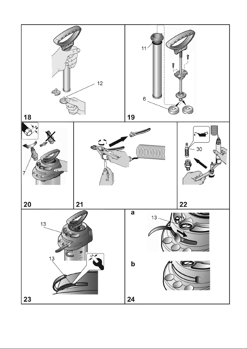
Care and maintenance
Observe the instructions in the section entitled “Safety”.
After using the device 50 times or at least once a year:
• Disassemble the sprayer [A] and grease the piston cup washer [6]. (Fig. 14 -15).
• Clean the spray tip [37-43] with the appropriate cleaning solvent or water. If required use a
needle. (Fig. 16).
• Remove the 200 mesh anti-siphon filter [35] from the end of the wand and the 100 mesh
filter location inside the trigger valve filter house [24] and clean thoroughly with the
appropriate solvent or water. (Fig. 17).
• Grease the seals [6] and [11 and 30]. (Fig. 19 and 22)
• Visually check the sprayer before each use for signs of leakage. Replace all worn parts.
Replace the tank if any holes are observed.
Troubleshooting
Use only NOX-CRETE spare and accessory parts (you will find some in the spare
parts container (page 2 and 3).
Problem
Cause
Remedy
No pressure builds up in
the device
The pump is not screwed on
tightly.
Screw the pump on tightly
O-ring [11] on the pump is
faulty.
Replace the O-ring. (Fig. 19).
Foot valve disk [12] defective.
Replace the foot valve.
(Fig. 18).
Piston washer [6] is defective.
Replace piston washer.
Liquid flows out of the
pump.
Foot valve disk [12] defective.
Clean or replace the foot valve
disk. (Fig. 18).
The sprayer does not
spray even though
pressure is present.
Filters [24 and 35]and / or
spray tip [37-43] blocked.
Pressure regulator [F] is set too
low.
Clean the filters or / and spray
tip. (Fig. 16 +17)
Turn pressure regulator dial
clockwise to increase pressure.

12
USA
IRL
AUS
GB
NZ
CDN
IND
Problem
Cause
Remedy
Safety valves blows off
too early.
Safety valve [7] is defective.
Replace safety valve. (Fig. 20).
The trigger valve does
not close.
Liquid emerges without
the lever being activated.
Seal [30] on the pressure bolt
not greased.
Defective valve pin assembly or
seal [30].
Grease the seal of the pressure
bolt. (Fig. 22).
Replace the valve pin assembly
or seal. (Fig. 22).
Pressure gauge is not
indicating any tank
pressure.
Pressure gauge [16] defective.
Replace pressure gauge. (Fig.
23 & 24)
Warranty
We guarantee that from the time it is first purchased for a period of the legally valid required
warranty period (maximum 3 years) this sprayer will not exhibit any material or processing
errors. If defects are discovered during the warranty period, Nox-Crete, Inc. or the distributor
in your area will repair the sprayer without charging for the labor or material or (at the
discretion of Nox-Crete, Inc.) replace the sprayer itself or its defective parts.
If such defects are discovered, please contact us immediately. We require a copy of the
invoice or cash register receipt for purchase of the device.
The warranty does not include wearing parts (seals, O-rings, diaphragm, etc.) or defects
which have occurred due to improper use or unforeseeable circumstances.
CE Declaration of Conformity
Products of series PERFECT (3615) meet the requirements of Pressure Equipment
Directive 97/23/EC and bear the CE marking.
Table of contents
Other nox-crete Paint Sprayer manuals

Popular Paint Sprayer manuals by other brands


Toro
Toro 41177 Multi-Pro 1250 Operator's manual

Parkside
Parkside PFS 280 A1 Operation manual

Anest Iwata
Anest Iwata WIDER2L-10G2P instruction manual

Campbell Hausfeld
Campbell Hausfeld AL1860 - METAL Operating instructions and replacement parts list

Hozelock
Hozelock 4507 manual

Anest Iwata
Anest Iwata OCX-128 instruction manual


