NPK C6CSD User manual

HYDRAULIC SHEET PILE
DRIVER
OPERATORS MANUAL
MODELS:
C6CSD, C8CSD
C10CSD
“Use Genuine NPK Parts”
© Copyright 2020 NPK Construction Equipment, Inc. www.npkce.com SD000-9605B Hyd Sheet
Pile Driver Operators Manual 4-20
7550 Independence Drive
Walton Hills, OH 44146-5541
Phone (440) 232-7900
Toll-free (800) 225-4379
Fax (440) 232-6294

CONTENTS
- 1 -
SAFETY..................................................................................................................................... 3
FORWARD................................................................................................................................ 5
SHEET PILE DRIVER APPLICATIONS..................................................................................... 5
MAINTENANCE......................................................................................................................... 6
STANDARD PRACTICES................................................................................................6
CARRIER COMPATIBILITY....................................................................................................... 7
SPECIFICATIONS..................................................................................................................... 8
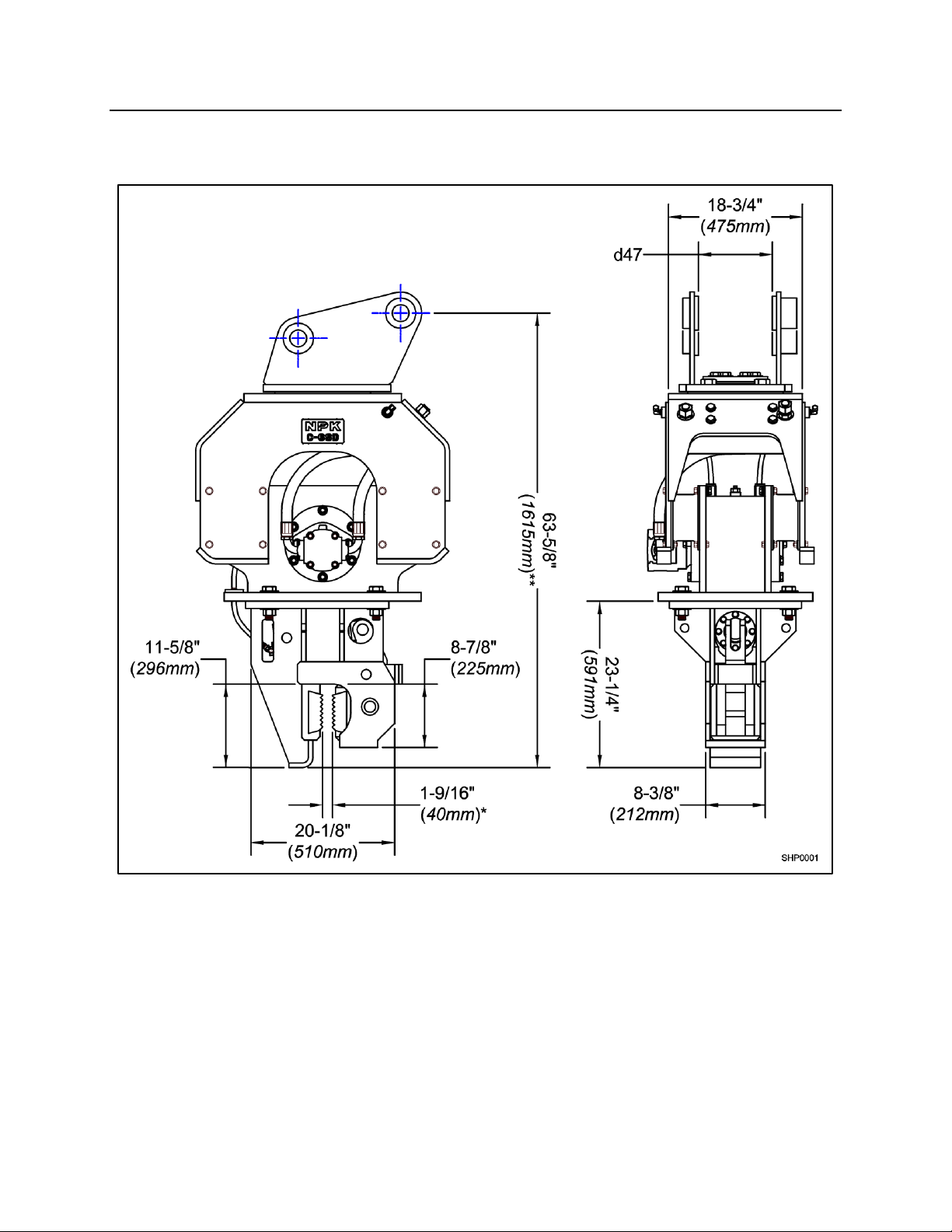
C6CSD............................................................................................................................9
C8CSD..........................................................................................................................10
C10CSD........................................................................................................................11
SHEET PILE DRIVER STRUCTURE........................................................................................12
C6CSD THROUGH C10CSD SHEET PILE DRIVERS...................................................12
SHEET PILE DRIVER SERIAL NUMBER LOCATION..............................................................15
HYDRAULIC INSTALLATION...................................................................................................16
NPK HYDRAULIC INSTALLATION KITS.......................................................................16
HYDRAULIC LINES.......................................................................................................16
SHUT-OFF VALVES......................................................................................................16
RETURN OIL.................................................................................................................17
PREVENTION OF CONTAMINATION...........................................................................18
CHANGING THE FILTER ELEMENT AND HYDRAULIC OIL.........................................18
CONTROL VALVES......................................................................................................19
CONTROL SYSTEM FOR CLAMP CYLINDER..............................................................20
HYDRAULIC QUICK DISCONNECTS...........................................................................21
NPK APPROVED CONNECTION QUICK DISCONNECTS ...........................................22
PRECAUTIONS ............................................................................................................22
MECHANICAL INSTALLATION................................................................................................24
MAINTENANCE AND INSPECTION.........................................................................................25
DAILY MAINTENANCE.................................................................................................25
SEMI-ANNUAL MAINTENANCE ...................................................................................26
REPLACE BEARING LUBRICATION OIL..........................................................26
TWENTY HOUR INSPECTION .....................................................................................27
JAW TOOTH PLATE (CHUCK) INSPECTION ...............................................................28
RUBBER MOUNT INSPECTION...................................................................................28
HOSE CONNECTIONS.................................................................................................29
LUBRICANT TERMS AND DEFINITIONS ................................................................................30
OIL CAPACITY SPECIFICATIONS...........................................................................................32
LOWER FRAME............................................................................................................32
BEFORE OPERATION.............................................................................................................33
DECIDE IF SWIVEL LOCK FEATURE WILL BE USED..................................................33
OPERATION.............................................................................................................................34
PRE-CHECKS...............................................................................................................34
CHECK FASTENERS FOR PROPER TIGHTNESS ..........................................34
JAW TOOTH PLATE (CHUCK) INSPECTION...................................................34
RUBBER MOUNT INSPECTION.......................................................................34
HOSE CONNECTIONS .....................................................................................35
CHECK SHUT-OFF VALVE POSITION.............................................................35
SHEET/PILE DRIVING AND EXTRACTING..................................................................36
SWIVEL FEATURE............................................................................................36
CHUCKING THE SHEET PILE......................................................................................38
LIFT THE SHEET PILE..................................................................................................38
POSITIONING THE SHEET PILE..................................................................................39
PILE DRIVING OPERATION.........................................................................................40
PULLING OPERATION.................................................................................................41

CONTENTS
- 2 -
OPERATIONAL PRECAUTIONS..............................................................................................42
STORAGE OF THE SHEET PILE DRIVER...............................................................................43
WARRANTY REGISTRATION FOR NEW UNITS.....................................................................44
WARRANTY STATEMENTS.....................................................................................................45
NOTES AND RECORDS..........................................................................................................47

NPK
- 3 -
SAFETY
Safety notices in NPK Instruction Manuals follow ISO and ANSI standards for
safety warnings:
DANGER (red) notices indicate an imminently hazardous situation
which, if not avoided, will result in death or serious injury.
WARNING (orange) notices indicate a potentially hazardous situation
which, if not avoided, could result in death or serious injury.
CAUTION (yellow) notices indicate a potentially hazardous situation,
which, if not avoided, may result in minor or moderate injury.
ATTENTION (blue) notices in NPK Instruction Manuals are an NPK
standard to alert the reader to situations which, if not avoided, could
result in equipment damage.
1. Operators and service personnel must read, understand and comply with the NPK
INSTRUCTION MANUAL.
2. Keep personnel and bystanders clear of the SHEET PILE DRIVER while in
operation.
3. Do not operate the SHEET PILE DRIVER without an impact resistant shield
between the SHEET PILE DRIVER and the operator.
4. The SHEET PILE DRIVER must not be operated unless the operator is in full
control of the carrier. Operate the SHEET PILE DRIVER from the operator’s seat
only.
5. Match the SHEET PILE DRIVER size to carrier according to NPK
recommendations. See the CARRIER MACHINE COMPATIBILITY section of this
manual.
6. Service personnel must be cautious handling pins and bushings when exchanging
the bucket for the SHEET PILE DRIVER. The carrier machine operator must move
the stick or boom only when directed by service personnel.
7. If it is necessary to hammer the boom pins in or out, beware of flying metal chips.
Eye protection be worn!
8. Do not operate the SHEET PILE DRIVER if the hydraulic oil temperature exceeds
180° F (80° C), or at higher than specified flow rates.
9. Be especially cautious around hydraulic lines. Hydraulic oil can be extremely HOT!
Avoid skin contact with hydraulic oil! It can cause severe burns!
10. Protect hands and body from hydraulic fluids under pressure. Escaping high
pressure fluid can penetrate the skin, causing serious injury. Avoid the hazard by
relieving the pressure form the hydraulic system before disconnecting any lines.
Search for leaks with a piece of cardboard or other object. If an accident occurs,
seek medical attention immediately! Hydraulic fluid injected into the skin
must be surgically removed immediately or gangrene may result!

NPK
- 4 -
SAFETY
11. Make daily visual inspections of all fasteners, boom pins, hoses, etc.
12. Do not make any alterations to the SHEET PILE DRIVER without authorization from
NPK Engineering.
13. Use only NPK supplied replacement parts. NPK specifically disclaims any
responsibility for bodily injury or SHEET PILE DRIVER damage that results from the
use of parts not sold or approved by NPK.
14. Be careful when you torque fasteners. An overstressed or damaged component
may fail.
15. Use the proper lifting equipment and tools when handling or servicing the SHEET
PILE DRIVER or components.
16. Important safety and operating decals are included with each SHEET PILE DRIVER
and HYDRAULIC INSTALLATION KIT. Keep them clean and visible. NPK will
replace decals free of charge as needed.

NPK
- 5 -
FORWARD
This manual has been written to give the necessary instructions for operating,
maintaining, and servicing the NPK Sheet Pile Driver. Read this manual before start-
up.
For help with any problems encountered, or additional information, contact your NPK
authorized Distributor.
Use replacement parts sold by NPK only. NPK is not responsible for failures resulting
from alterations not approved by NPK or substitution of parts not sold by NPK. Do not
operate the Sheet Pile Driver underwater without instructions from NPK Engineering.
SHEET PILE DRIVER APPLICATIONS
The excavator mounted Sheet Pile Driver is a mobile, self-contained unit that operates
anywhere a boom can reach. This versatile attachment reaches to the top of piling and
sheeting for driving or extracting in the toughest of conditions and in rough terrain areas.
APPLICATIONS INCLUDE:
•DRIVING PILE, SHEET.
•EXTRACTION OF PILING AND SHEETING.

NPK
- 6 -
MAINTENANCE
STANDARD PRACTICES
Maintenance of and repairs to the SHEET PILE DRIVER should be performed by an
experienced service technician, thoroughly familiar with all standard practices and
procedures, and most importantly, all safety precautions. The following is a review of
common standard practices to be followed when working with hydraulic equipment, and
is not meant to be all-inclusive. Rather, this review is presented as a reminder as to
some of the unique characteristics of hydraulic equipment.
•The prevention of foreign contaminant damage is critical when working with hydraulic
equipment. Protect exposed holes and parts to guard against entry of contaminants.
Install metal or plastic plugs/caps where applicable to prevent entry of debris into the
hydraulic system.
•Mark the location and position of mating parts as an aid to re-assembly. Mark
corresponding parts uniquely to reflect their relationship, including proper location,
position, orientation, and/or alignment.
DO:
•During assembly, observe all markings made during disassembly, and all
corresponding features of mating parts to ensure proper location, position, orientation
and alignment.
•During disassembly of a sub-assembly, place removed components on a clean, dry
surface, in proper relative position as an aid in re-assembly.
•Always inspect threaded areas on components. Repair or replace as required.
Never apply uncured thread adhesive to a fastener that has cured adhesive on it.
Clean the fastener and the threaded bore. A tap and die may be helpful for this task.
Be sure to remove loose debris from the threaded bore.
•Use care to avoid scratches, nicks, dents, or other damage to machined surfaces of
mating components.
•When securing a component, always tighten cap screws gradually in an opposing
pattern, applying the specific torque.
•Grease can be used to temporarily hold a part in place while the abutting part is
placed into position.
•Always use common sense and exercise standard safety precautions when working
with all tools and equipment required to maintain, repair or troubleshoot the SHEET
PILE DRIVER.

NPK
- 7 -
CARRIER COMPATIBILITY
These carrier weight ranges are intended as a guideline only. Other factors, such as
stick length, counterweights, undercarriage, etc., must be taken into consideration.
Mounting a Compactor that is too heavy for the carrier machine is inefficient. The result
is an inadequate amount of downforce which can be dangerous and can damage the
carrier. Verify the carrier stability with the Compactor before transport or operation.
Mounting a Compactor that is too small for the carrier machine can damage the unit and
void the Warranty.
Consult NPK, if there is uncertainty whether the compactor model is compatible.
COMPACTOR/DRIVER
RECOMMENDED CARRIER WEIGHT
MODEL
lb.
(kg)
C6CSD
16,000 - 42,000
(7,000 - 19,000)
C8CSD
30,000 - 65,000
(14,000 - 29,500)
C10CSD
60,000 - 100,000
(27,000 - 45,000)
(Specifications subject to change without notice.)

NPK
- 8 -
SPECIFICATIONS
MODEL
CYCLES
OIL FLOW
OIL FLOW
OIL FLOW
PER
(standard)
(low flow option)
(high flow option)
MINUTE
gpm
(lpm)
gpm
(lpm)
gpm
(lpm)
C6CSD
2,200
33
(125)
25.5
(97)
N/A
C8CSD
2,200
43
(160)
CONTACT NPK
N/A
C10CSD
2,200
51
(210)
CONTACT NPK
N/A
MODEL
IMPULSE
OPERATING
RELIEF VALVE
FORCE
PRESSURE₁
PRESSURE SETTING2
lbf
(kgf)
psi
(bar)
psi
(bar)
C6CSD*
16,000
(7,300)
1800-2300
(125-160)
2600
(180)
C8CSD*
24,000
(11,000)
2000-2500
(140-170)
2600
(180)
C10CSD*
34,000
(15,450)
2000-2500
(140-170)
2600
(180)
*The carrier circuit relief valve settings should be a minimum of 200psi (14 bar) above the sheet driver
relief settings.
1. Operating pressures shown are with a standard hydraulic motor. Operating pressures will be different
with optional hydraulic motors.
2. Relief pressure setting shown is for a standard hydraulic motor. For a relief with different motor options,
contact NPK at 1-800-225-4379.
(Specifications subject to change without notice.)
MODEL
CHUCK CYLINDER
CHUCK CYLINDER
OIL FLOW
OP. PRESSURE
gpm
(lpm)
psi
(bar)
C6CSD
3 - 5
(11 - 20)
3045
(210)
C8CSD
3 - 5
(11 - 20)
3045
(210)
C10CSD
3 - 5
(11 - 20)
3045
(210)

NPK
- 9 -
SPECIFICATIONS
C6CSD
DIMENSION d47: variable
* = Maximum opening
** = Subject to change
WORKING WEIGHT: 2150 lbs. (975 kg)

NPK
- 10 -
SPECIFICATIONS
C8CSD
DIMENSION d47: variable
* = Maximum opening
** = Subject to change
WORKING WEIGHT: 2750 lbs. (1250 kg)

NPK
- 11 -
SPECIFICATIONS
C10CSD
DIMENSION d47: variable
* = Maximum opening
** = Subject to change
WORKING WEIGHT: 4130 lbs. (1875 kg)

NPK
- 12 -
SHEET PILE DRIVER STRUCTURE
C6CSD THROUGH C10CSD SHEET PILE DRIVERS
The C6CSD through C10CSD SHEET PILE DRIVERS consist of a top bracket, an
upper frame, a lower frame and a cylinder assembly. The C6CSD, C8CSD and
C10CSD SHEET PILE DRIVERS are available with a fixed or a swivel top bracket.
The C6CSD and C8CSD upper frame is mounted to the lower frame with (4) bolt-on
rubber mounts. C10CSD models use (8) rubber mounts. The rubber mounts reduce
the amount of vibration being transmitted to the excavator.
The lower frame contains an eccentric weight suspended on roller bearings and spun by
a hydraulic motor. The cylinder assembly is bolted to the lower frame. The upper frame
also contains a bolt-on hydraulic manifold.
MODEL C6CSD
SWIVEL
ITEM
DESCRIPTION
BQ
HYDRAULIC MOTOR
c11
CYLINDER ASSEMBLY
DY
RUBBER MOUNT
EG
UPPER FRAME
EI
THRUST COVER
EJ
UPPER THRUST PLATE
EJ1
LOWER THRUST PLATE
EK
THRUST BEARING
FK
SWIVEL HUB (weld-on)
m7
TOP BRACKET
sp2
LOWER FRAME
sp3
CYLINDER CASE

NPK
- 13 -
SHEET PILE DRIVER STRUCTURE
C6CSD THROUGH C10CSD SHEET PILE DRIVERS
MODEL C8CSD
SWIVEL
ITEM
DESCRIPTION
BQ1
HYDRAULIC MOTOR
c11
CYLINDER ASSEMBLY
DY
RUBBER MOUNT
EG
UPPER FRAME
EI
THRUST COVER
EJ
UPPER THRUST PLATE
EJ1
LOWER THRUST PLATE
EK
THRUST BEARING
FK
SWIVEL HUB (weld-on)
m7
TOP BRACKET
sp2
LOWER FRAME
sp3
CYLINDER CASE

NPK
- 14 -
SHEET PILE DRIVER STRUCTURE
C6CSD THROUGH C10CSD SHEET PILE DRIVERS
MODEL C10CSD
SWIVEL
ITEM
DESCRIPTION
BQ
HYDRAULIC MOTOR
c11
CYLINDER ASSEMBLY
DY
RUBBER MOUNT
EG
UPPER FRAME
EI
THRUST COVER
EJ
UPPER THRUST PLATE
EJ1
LOWER THRUST PLATE
EK
THRUST BEARING
FK
SWIVEL HUB (weld-on)
m7
TOP BRACKET
sp2
LOWER FRAME
sp3
CYLINDER CASE

NPK
- 15 -
SHEET PILE DRIVER SERIAL NUMBER
LOCATION
The serial number of your unit is required any time that you are placing a parts order or
requiring technical assistance. Failure to use the serial number when ordering parts,
may result in receiving the incorrect parts, resulting in additional cost and down time.
The serial number will be comprised of the following sequence of numbers and letters:
0N-0000.
The location described below is between the inlet and outlet hydraulic ports on the
upper frame.
The serial number tag (sn2) can be found on the upper frame assembly. Additionally,
the serial number (sn1) is stamped below the serial number tag on the upper frame
assembly.

NPK
- 16 -
HYDRAULIC INSTALLATION
NPK HYDRAULIC INSTALLATION KITS
NPK Hydraulic Installation Kits are available for virtually all compatible backhoe and
excavator models. The kits include all parts and complete instructions for the hydraulic
installation, including valves, electrical or manual controls, hoses and fittings, boom and
stick piping and clamps.
See your NPK dealer for details or call NPK direct at 1-800-225-4379.
HYDRAULIC LINES
Typically, the pressure line is arranged on the left side of the boom and the return line is
on the right side.
SHUT-OFF VALVES
Most NPK Hydraulic Installation Kits use two shut-off valves (k4) on the dipper stick (k1)
of the carrier. These valves control the hydraulic oil going to the pressure side (m3) and
returning (m4) from the Compactor/Driver. (NOTE: Some smaller carriers utilize a
check valve on the return side.)

NPK
- 17 -
HYDRAULIC INSTALLATION
SHUT-OFF VALVES
Pressure test ports (k8) are located in the shut-off valves (and check valves). Each
shut-off valve has an “ON” (k5) and an “OFF” (k6) position.
NOTE: When operating the NPK Compactor/Driver on a carrier with a return line shut-
off valve, be sure the valve is turned to the “ON” position to prevent damage to the
Compactor/Driver’s hydraulic motor.
RETURN OIL
The return line must be routed correctly and sized large enough to handle the oil flow
without creating excessive back pressure. The return oil MUST NOT go through a
control valve. It must be connected directly to the carrier’s hydraulic reservoir via the oil
cooler and return filter (or an NPK filter, if supplied).
To prevent failure of the hydraulic motor shaft seals, motor shaft or motor thrust plates,
the return line back pressure must not exceed 150 psi (10 bar). See the
“TROUBLESHOOTING”, MEASURING BACK PRESSURE section of the
INSTRUCTION MANUAL.
MODEL
MINIMUM LINE SIZE
in.
(mm)
C6CSD
1.00
(25.40)
C8CSD
1.25
(31.75)
C10CSD
1.25
(31.75)

NPK
- 18 -
HYDRAULIC INSTALLATION
PREVENTION OF CONTAMINATION
1. A SHEET PILE DRIVER is harder on oil than using a bucket, so the oil is apt to
deteriorate and breakdown sooner. Neglect of the oil system can not only damage
the SHEET PILE DRIVER, but also cause problems in the carrier which could
result in damaged components. Care should be taken to check for contamination
of the oil and to change it if it is found contaminated. Oil sampling at regular
intervals is highly recommended.
❖When the hydraulic oil shows low viscosity and bubbles, this indicates that the oil
is deteriorated. If the oil is dark brown and gives off an offensive odor, it is
severely deteriorated. Change the oil immediately!
❖When the oil is clouded, or the oil filter often becomes clogged, it indicates that the
oil is contaminated. Change the oil immediately!
❖To change the contaminated hydraulic oil, drain the hydraulic system completely
and clean components. Do not mix new oil with the old!
2. Do not allow any contamination to mix with the oil. Take special care in preventing
contamination from entering the hydraulic system through the hose or tube
connection when changing the SHEET PILE DRIVER with the bucket.
3. Low oil level will cause heat build-up, resulting in deterioration of the oil. Also, it
may cause cavitation due to air mixing with the oil, leading to a damaged
compactor/driver and carrier components. Keep the oil at the proper level at all
times.
4. Do not use the SHEET PILE DRIVER at an operating temperature higher than
180°F (80°C). The proper operating oil temperature range is between 120°F
(50°C) and 180°F (80°C). Since contaminated cooler fins causes reduced
efficiency of the cooler, keep the cooler fins clean at all times. Check the hydraulic
oil cooling system to be sure it is working effectively. The use of a heat gun is the
best way to evaluate if the cooler is working properly.
5. Water in the hydraulic oil will lead to damage of the SHEET PILE DRIVER and
carrier. Drain off water and foreign matter from the hydraulic tank at specified
intervals. When out of service, the SHEET PILE DRIVER should be stored
indoors.
CHANGING THE FILTER ELEMENT AND HYDRAULIC OIL
Change the filter element and hydraulic oil at the intervals described in the operation
manual of the backhoe or excavator, when using a hydraulic implement. Another
method is to set up an oil sampling schedule and change accordingly.

NPK
- 19 -
HYDRAULIC INSTALLATION
CONTROL VALVES
One of two types of control systems are used, depending upon the backhoe or
excavator used:
1. CONTROL SYSTEM USING THE EXCAVATOR AUXILIARY VALVE
This type of installation uses an existing excavator auxiliary valve (k7) to operate the
NPK Sheet Pile Driver (SD). Additional parts, such as mechanical linkage, hydraulic
pilot control valves (k11), etc., are furnished in the NPK HYDRAULIC INSTALLATION
KIT.
2. CONTROL SYSTEM USING THE NPK MULTIVALVE
For excavators not equipped with an auxiliary or spare valve section as part of the
control valve bank (k9), the NPK HYDRAULIC INSTALLATION KIT typically includes
a solenoid operated, priority valve (k10) to operate the NPK Sheet Pile Driver (SD).
The NPK MULTIVALVE is specifically designed for the operation of boom mounted
attachments.
This manual suits for next models
2
Table of contents
Other NPK Construction Equipment manuals
Popular Construction Equipment manuals by other brands

Bend-Pak
Bend-Pak BB 1302-BA Operation and service manual

Weber mt
Weber mt CFR 90 Operating and maintenance manual

ACP
ACP RiderPro Product and installation manual

Tadano Faun
Tadano Faun ATF 80-4 Operating, Service and Maintenance Manual

Draper
Draper CM170 Instructions for use

Komatsu
Komatsu D475A-3 Operation & maintenance manual