Power Fist 660 lb User manual

V 4.0 8622979
User Manual
660lbPower
Wheelbarrow
Please read and understand all instructions before use. Retain this manual for
future reference.

8622979 660 lb Power Wheelbarrow V 4.0
SPECIFICATIONS
Engine Type 196cc Powerfist
Transmission 4 speed (3 Forward and 1 Reverse)
Load Capacity 660 lb (300 kg)
Box Dimensions (L x W x H) 33-7/8 x 24-3/4 x 1-3/8 in.
Weight (Empty) 394.5 lb (179 kg)
INTRODUCTION
The 660 lb Power Wheelbarrow is great for landscaping and construction
applications including hauling dirt, sod, sand, gravel, shrubs, etc. The rubber
tracks minimize ground damage and can easily travel over uneven surfaces. The
4 speed transmission makes it easy to transport loads up to 660 lb (300 kg)
across rough terrain. The dump box is easy to empty and is secured in place by
the latched tipping handle.
SAFETY
WARNING! Read and understand all instructions before using this tool. The
operator must follow basic precautions to reduce the risk of personal injury
and/or damage to the equipment.
Keep this manual for safety warnings, precautions, operating or inspection and
maintenance instructions.
HAZARD DEFINITIONS
Please familiarize yourself with the hazard notices found in this manual. A notice
is an alert that there is a possibility of property damage, injury or death if certain
instructions are not followed.
660lbPower
Wheelbarrow
2 For technical questions call 1-800-665-8685

V 4.0 660 lb Power Wheelbarrow 8622979
DANGER! This notice indicates an immediate and specific hazard that will
result in severe personal injury or deathif the proper precautions
are not taken.
WARNING! This notice indicates a specific hazard or unsafe practice that
could result in severe personal injury or death if the proper
precautions are not taken.
CAUTION! This notice indicates a potentially hazardous situation that may result
in minor or moderate injury if proper practices are not taken.
NOTICE! This notice indicates that a specific hazard or unsafe practice will
result in equipment or property damage, but not personal injury.
WORK AREA
1. Operate in a safe work environment. Keep your work area clean, well lit and
free of distractions.
2. Keep anyone not wearing the appropriate safety equipment away from the
work area.
3. Store unused tools properly in a safe and dry location to prevent rust or
damage. Lock tools away and keep out of the reach of children.
4. Do not install or use in the presence of flammable gases, dust or liquids.
PERSONAL SAFETY
WARNING! Wear personal protective equipment approved by the
Canadian Standards Association (CSA) or American National Standards
Institute (ANSI).
PERSONAL PROTECTIVE EQUIPMENT
1. Always wear impact safety goggles that provide front and side protection
for the eyes. Eye protection equipment should comply with CSA Z94.3-07
or ANSI Z87.1 standards based on the type of work performed.
2. Wear gloves that provide protection based on the work materials or to
reduce the effects of tool vibration.
3. Wear protective clothing designed for the work environment and tool.
4. Non-skid footwear is recommended to maintain footing and balance in the
work environment.
Visit www.princessauto.com for more information 3

8622979 660 lb Power Wheelbarrow V 4.0
5. Wear steel toe footwear or steel toe caps to prevent a foot injury from
falling objects.
6. This tool can cause hearing damage. Wear hearing protection gear with an
appropriate Noise Reduction Rating to withstand the decibel levels.
PERSONAL PRECAUTIONS
Control the tool, personal movement and the work environment to avoid
personal injury or damage to tool.
1. Do not operate any tool when tired or under the influence of drugs, alcohol
or medications.
2. Avoid wearing clothes or jewelry that can become entangled with the
moving parts of a tool. Keep long hair covered or bound.
3. Do not overreach when operating a tool. Proper footing and balance
enables better control in unexpected situations.
4. Securely hold this tool using both hands. Using a tool with only one hand
can result in loss of control.
SPECIFIC SAFETY PRECAUTIONS
WARNING! DO NOT let comfort or familiarity with product (gained from
repeated use) replace strict adherence to the tool safety rules. If you use
this tool unsafely or incorrectly, you can suffer serious personal injury.
1. Use the correct tool for the job. This tool was designed for a specific function.
Do not modify or alter this tool or use it for an unintended purpose.
2. Do not exceed the power wheelbarrow’s load capacity (see Specifications).
3. Do not use the machine if the engine’s switch does not turn it on or off.
Any gasoline powered machine that cannot be controlled with the engine
switch is dangerous and must be replaced.
4. Position the machine in such a way that it cannot move during maintenance,
repairs, cleaning, adjustments, assembly of accessories or storage.
Unexpected movement can cause a crushing injury during these procedures.
5. Do not operate the machine in confined areas where there may be a risk of
crushing the operator between the machine and another object. Use
extreme caution when in reverse or pulling the machine towards you.
4 For technical questions call 1-800-665-8685

V 4.0 660 lb Power Wheelbarrow 8622979
6. Never carry passengers on the power wheelbarrow.
7. Drive at a safe speed and adjust for the surface conditions and the load.
8. Never operate the machine on slopes where angle is over 20°.
a. Do not shift gears while on a slope.
b. Ensure the load is evenly balanced when moving over a slope in
forward or reverse.
9. The power wheelbarrow’s center-of-gravity will change when tipping a load
out. Ensure the machine is on firm, stable ground capable of supporting
the change as the load shifts.
a. Soft or slick surfaces may cause the power wheel barrow to tip or slip
during unloading.
UNPACKING
WARNING! Do not operate the tool if any part is missing. Replace the
missing part before operating. Failure to do so could result in a malfunction
and personal injury.
Remove the parts and accessories from the packaging and inspect for damage.
Make sure that all items in the parts list are included.
Contents:
• Main Frame
• Handlebar Assembly
• Tipping Handle
• Dump Box
• Hardware
Visit www.princessauto.com for more information 5

8622979 660 lb Power Wheelbarrow V 4.0
IDENTIFICATION KEY
A Engine Switch
B Throttle Control
C Right Steering Lever
D Clutch Control Lever
E Left Steering Lever
F Dump Box
G Gear Selection Lever
H Tipping Handle
I Track
J Gearbox
Engine Switch -The engine switch enables and disables the ignition system. The
engine switch must be in the ON position for the engine to run. Turning the
engine switch to the OFF position stops the engine.
Throttle Control - Controls engine speed. Set the power wheelbarrow’s speed to
low (L), middle and high (H) speed.
Right Steering Lever - Operate the lever to turn right.
Clutch Control Lever- Squeeze the control lever to engage the clutch. Release
the lever to disengage clutch.
Left Steering Lever - Operate the lever to turn left.
Gear Selection Lever – Switch between forward and reverse.
Tipping Handle - Pull the tipping handle up to release the dump box's locking
device and raise the dump box. Pull the tipping handle down to its original position.
When the dump box is lowered, the locking mechanism locks the dump box. Lift
the dump without using the tipping handle to confirm it is locked in position.
ASSEMBLY & INSTALLATION
When this manual refers to a part number, it refers to the included Parts List.
1. Mount the tipping handle onto the panel’s right side. Align the holes and
fasten with two M8x35 hex bolts, four washers and two nuts (Fig. 2).
Fig. 1
6 For technical questions call 1-800-665-8685

V 4.0 660 lb Power Wheelbarrow 8622979
2. Align the holes of the handlebar with the mounting bracket and secure
each with a spring washer, flat washer and an M10x20 bolt. Fasten each
handlebar support onto the engine deck with a spring washer, flat washer
and an M8x25 hex bolt (Fig. 3).
3. Position the bottom panel inside the mounting bracket. Align the holes with
the mounting bracket. Insert a long pin through holes and secure each side
with a flat washer and cotter pin (Fig. 4).
OPERATION
Consult the engine manual for the correct procedure to start and stop the
engine.
1. Start the engine. After the engine warms up, adjust the throttle control (B)
to increase the engine speed.
2. Choose a gear with the gear selection lever (G) and slowly squeeze the
clutch control lever (D) to start moving. If the gear does not engage
straight away, slowly release the clutch lever and try again.
3. The power wheelbarrow has steering levers on the handlebars (C and E).
To turn right, squeeze the right steering lever to slow or stop the track on
that side. The power wheelbarrow will then turn in that direction.
The steering sensitivity increases in proportion to the speed of the
machine. Light pressure on the lever is all that is needed to turn an empty
machine. More pressure is required when the machine is loaded.
Fig. 2
Fig. 3
Fig. 4
Visit www.princessauto.com for more information 7

8622979 660 lb Power Wheelbarrow V 4.0
4. When the clutch control lever is released, the machine will stop
automatically.
5. Move the Gear Select Lever (G) to neutral.
a. Switch the engine OFF as an additional safety precaution.
6. Dump the load by pulling the tipping handle (H) up to release the dump
box's locking device. Manually raise the dump box to dump the load.
Lower the dump box and the locking mechanism will automatically lock the
box into place. Confirm the dump box is locked into position by attempting
to lift the dump box without using the tipping handle.
DIFFICULT TERRAIN
The power wheelbarrow may be hard to control when carrying a full load on
difficult terrain. The following steps can reduce the chance of losing control of
the equipment.
1. Reduce the power wheelbarrow’s speed to low on difficult terrain such as
soft or frozen ground, on an incline or on loose gravel or stones. This will
allow more time to react to a potential loss of control.
2. Do not allow rapid acceleration, sudden stops or sharp turns. The load’s
momentum can cause the power wheelbarrow to tip or slide in an
unexpected direction.
3. The power wheelbarrow will tilt when the tracks pass over obstacles or
rough terrain.
4. Adverse weather conditions such as wind, rain, snow and ice can make the
power wheelbarrow more difficult to control. Reduce speed and evaluate
the terrain.
a. Rough terrain can wear down the rubber tracks quickly, impairing
their function and reducing their operational life,
5. Place a wedge against one of the tracks if the machine is stopped on a
steep slope.
CARE & MAINTENANCE
1. Maintain the tool with care. A tool in good condition is efficient, easier to
control and will have fewer problems.
8 For technical questions call 1-800-665-8685

V 4.0 660 lb Power Wheelbarrow 8622979
2. Inspect the tool components periodically. Repair or replace damaged or
worn components. Only use identical replacement parts when servicing.
3. Follow instructions for lubricating and changing accessories.
4. Keep the tool handles clean, dry and free from oil/grease at all times.
5. Maintain the tool’s labels and name plates. These carry important information.
If unreadable or missing, contact Princess Auto Ltd. for replacements.
WARNING! Only qualified service personnel should repair the tool. An
improperly repaired tool may present a hazard to the user and/or others.
PREVENTIVE MAINTENANCE
Turn off the engine and place the gear selection lever into neutral. Wait until the
engine is cool. Remove all debris and other materials that may have
accumulated on the tracks, engine or chassis.
ADJUSTING THE CLUTCH
A worn clutch may require moving the clutch lever farther before the clutch
engages.
1. Set the clutch lever to its original position.
2. Remove slack from the clutch lever cable with the adjustment device and
counter-nut.
ADJUSTING THE STEERING
The steering system may become less responsive with wear and tear to the unit.
Adjust one steering lever, before adjusting the other one.
1. Loosen the locknut and unscrew the adjuster just enough to allow the
cable to move when force is applied. Do not loosen too much as traction
can be lost.
2. Eliminate slack in the cable and tighten the adjuster.
3. Tighten the locknut and test the tension in the steering lever.
TIGHTEN TRACKS
WARNING! An overtight track will impair the brake’s effectiveness. Test and
adjust the brakes after tightening the track. Replace the track if any
adjustment affects the brakes normal function.
Visit www.princessauto.com for more information 9
8622979 660 lb Power Wheelbarrow V 4.0
A loose track can slip off the driving wheel. This can cause a hazardous
situation or damage to the equipment. Check the track’s tightness on a
regular basis.
1. Set the machine on a flat surface of asphalt,
stone or pavement. Compact ground is also
acceptable.
2. Lift the machine and set it on blocks or
supports rated for the weight of the
machine, so that the tracks are
approximately 4 in (100 mm) off the
ground.
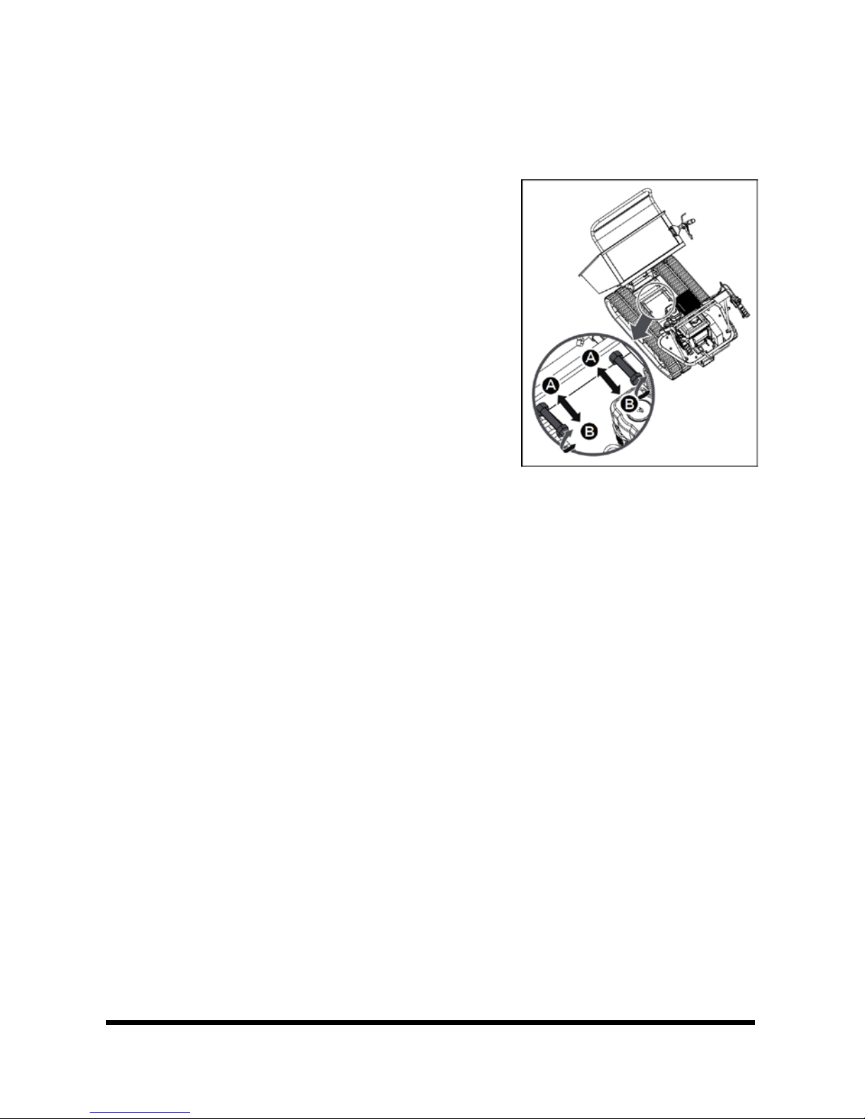
3. Measure the track midline vs. the horizontal
line. The reading must not be more than
10-15 mm. If the distance is greater,
proceed as follows (Fig. 5).
a. Tip the dump box and set it on blocks or supports capable of holding
the weight of the box.
b. Loosen locknut A.
c. Tighten bolt B until the correct tightness is restored to the track.
d. Secure bolt B by retightening locknut A to secure the bolt in place.
e. Return the dump box to its original position.
NOTICE! Replace the track if the guide wheel axle (#71) is fully extended
forward and the track is still too loose.
REPLACING A TRACK
WARNING! Keep hands away from the track and wheels when under power to
avoid a crushing injury.
Check the condition of the tracks periodically. Replace a track that is cracked or
frayed.
1. Set the machine on a flat surface of asphalt, stone or pavement. Compact
ground is also acceptable.
2. Lift the machine and set it on jack stands or supports rated for the weight
of the machine. The tracks should be 4 in. (100 mm) off the ground.
Fig. 5
10 For technical questions call 1-800-665-8685

V 4.0 660 lb Power Wheelbarrow 8622979
3. Loosen locknut A and bolt B (Fig. 5) fully to release tension from the track.
4. Pull the track off the toothed drive wheel at the rear by hand if possible. An
alternative is to use a wood block and crowbar to remove the track.
a. Start the engine and shift the power wheelbarrow into reverse.
b. Place a long wood block against the track and drive wheel. The wood
block will lift the track off the drive wheel as it rotates. Place the
power wheelbarrow into neutral gear as soon as the track has lifted.
c. Pull the track towards the side with the crowbar until the track slides
off the wheel. Remove the wood block.
WARNING! Do this carefully to avoid tipping the machine over. The machine
is heavy and can cause a crushing injury.
d. Shut the engine OFF.
e. Pull the track off the other wheels.
5. Place the new track so the teeth
are on either side of the front
wheel. Position the track so it
aligns with the other wheels.
6. Place the track on the rear drive
wheel by hand if possible. Use a
crowbar to slip the track onto the
teeth of the drive wheel.
7. Start the engine and place the
power wheelbarrow in reverse until the drive wheel’s teeth slip into the
slotted holes of the track.
8. Adjust the track tension as explained in the section Tighten Tracks.
ENGINE MAINTENANCE
Refer to the Engine Manual included in your unit for the information on engine
maintenance. Your engine manual provides detailed information and a
maintenance schedule for performing the tasks.
Fig. 6
Visit www.princessauto.com for more information 11

8622979 660 lb Power Wheelbarrow V 4.0
CLEANING
Never use a pressure washer to clean the power wheelbarrow. Water can
penetrate tight areas of the machine or its transmission case and cause damage
to spindles, gears, bearings or the engine. This can shorten the equipment’s
operational life and reduce serviceability.
Do not use strong detergents or petroleum based cleaners when cleaning
plastic parts. Chemicals can damage plastics.
LUBRICATION
Inspect and lubricate the tool when required. Only use a premium quality
lightweight machine oil to lubricate the tool. Other lubricants may not be
suitable and could damage the tool or cause a malfunction during use.
NOTICE! NEVER use a penetrating oil to lubricate the tool. Penetrating oil may
act as a solvent that can break down the grease and cause the tool to seize up.
STORAGE
If the power wheelbarrow will not be used for a period be used for a period
longer than 30 days, follow the steps below to prepare your unit for storage.
Consult the engine manual for storage steps involving the engine.
1. Use clean cloths to clean off the outside of the machine and to keep the air
vents free of obstructions.
2. Inspect for any loose or damaged parts. Repair or replace damaged parts
and tighten loose screws, nuts or bolts.
3. Store your unit on flat ground in a clean, dry building that has good
ventilation.
DISPOSAL
Recycle a tool damaged beyond repair at the appropriate facility.
Contact your local municipality for a list of disposal facilities or by-laws for
electronic devices, batteries, oil or other toxic liquids.
IMPORTANT! DO NOT pollute the environment by allowing uncontrolled
discharge of waste oil.
12 For technical questions call 1-800-665-8685

V 4.0 660 lb Power Wheelbarrow 8622979
TROUBLESHOOTING
Visit a Princess Auto Ltd. location for a solution if the tool does not function
properly or parts are missing. If unable to do so, have a qualified technician
service the tool.
Consult the engine manual for further troubleshooting steps and solutions.
Problem(s) Possible Cause(s) Suggested Solution(s)
One of the two
tracks is blocked.
Foreign bodies have worked
their way between the track
and the frame.
Remove the foreign body.
Machine does not
move while engine
is running.
1. Gear is not properly
selected.
2. Driving tracks not tight
enough.
1. Ensure gear lever is not
in-between two different
gears.
2. Tighten driving tracks.
Visit www.princessauto.com for more information 13
8622979 660 lb Power Wheelbarrow V 4.0
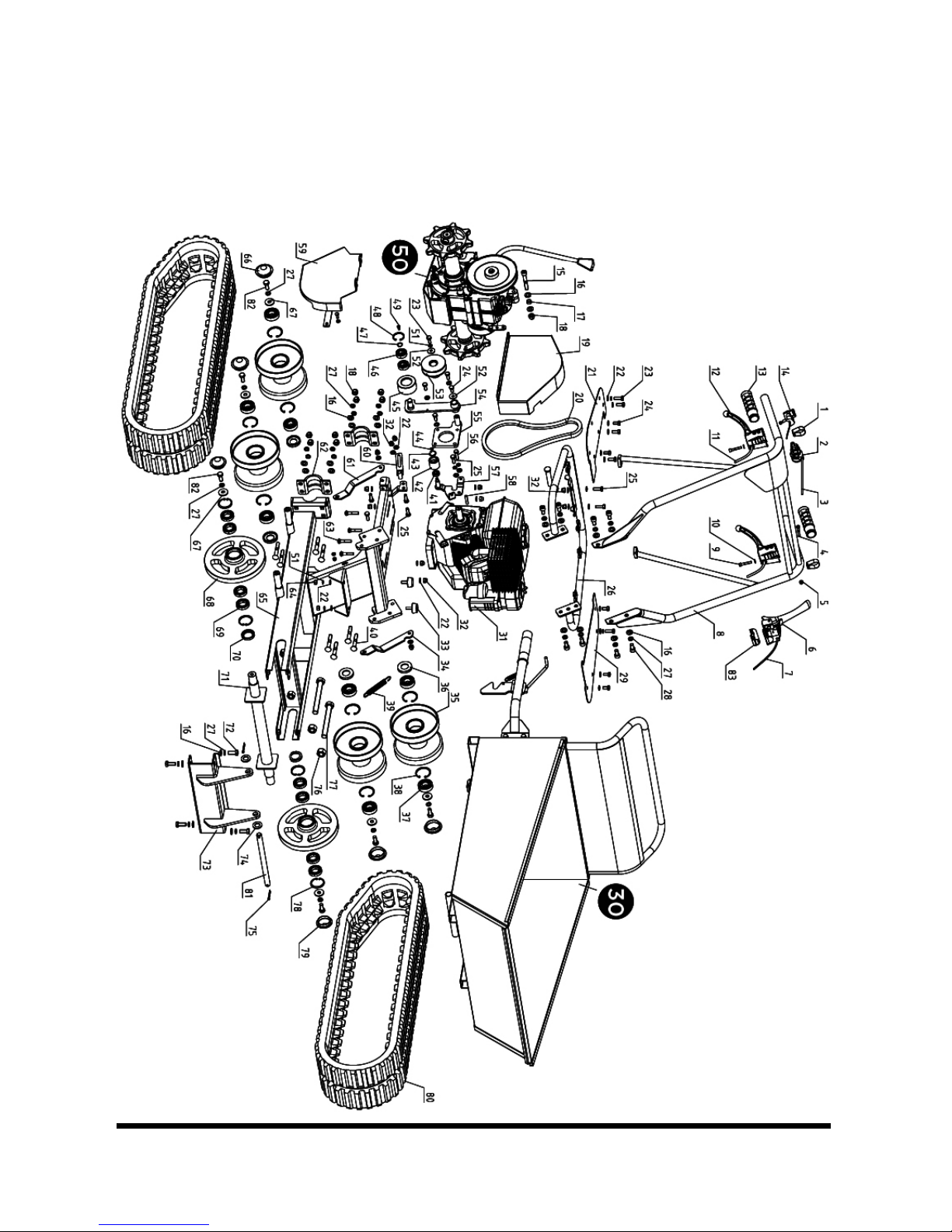
PARTS BREAKDOWN
POWER WHEELBARROW
14 For technical questions call 1-800-665-8685
V 4.0 660 lb Power Wheelbarrow 8622979
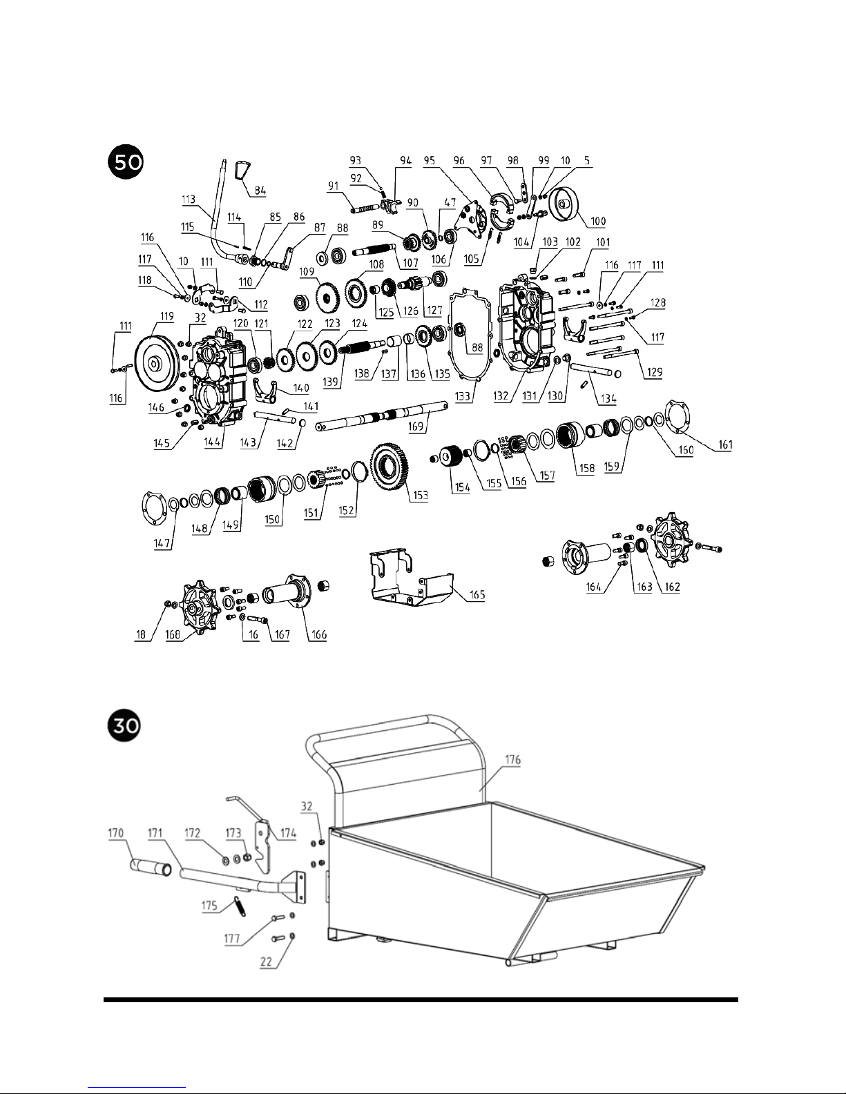
GEAR BOX
DUMP BOX
Visit www.princessauto.com for more information 15

8622979 660 lb Power Wheelbarrow V 4.0
PARTS LIST
PART#
DESCRIPTION QTY
1 Hoop 2
2 Throttle Lever 1
3
Throttle Cable
1
4 Bolt M6x40 1
5
Nut M6
5
6 Clutch Control Lever 1
7 Clutch Control Lever Cable 1
8 Handle Frame Assembly 1
9
Bolt M6x35
2
10 Washer Ø6 5
11
Right/Left Steering Lever
Cable
2
12 Right/Left Steering Lever 2
13 Handle Sleeve 2
14 ON/OFF Switch 1
15 Bolt M10x10 1
16 Washer Ø10 38
17 Bush 1
18 Lock Nut M10 12
19 Small Belt Pulley Cover 1
20 Belt B770 1
21 Soleplate (R) 1
22 Washer Ø8 40
23 Bolt M8x20 7
24 Bolt M8x16 6
25 Bolt M8x25 11
26 Handle Mounting Frame 1
27 Washer Ø10 36
28 Bolt M10x20 8
29 Soleplate (L) 1
30 Dump Box Assembly 1
31 Engine 1
32
Bolt M8
27
33 Rubber Washer 2
34
Support Plate (L)
1
35 Support Wheel 1
36 Gasket 25x47x7 1
37 Bearing 6204-2RS 2
38
Circlip 47
2
39 Spring 1
40
Bolt M10x65
8
41 Bearing 608 1
42 Compression Roller 1
43 Circlip 22 1
44
Circlip 8
1
45 Tensioner Pulley 1
46 Bearing 6202 2
47 Circlip 15 2
48 Circlip 35 1
49 Bolt M5x12 1
50
Gear Box
1
51 Washer Ø8 12
52
Big Washer Ø8
2
53 Small Belt Pulley 1
54 Tensioner Pulley Bracket 1
55 Fixed Bracket 1
56
Bolt M8x30
3
57 Compression Roller
Mounting Plate
1
16 For technical questions call 1-800-665-8685

V 4.0 660 lb Power Wheelbarrow 8622979
58
Key 5x35
1
59 Large Belt Pulley Cover 1
60
Belt Plate
1
61 Support Plate (R) 1
62 Wheel Axle Fixing Plate 2
63 Bolt M8x40 4
64
Nut M8
2
65 Chassis 1
66 Ø47 Axle Head Cover
(Support Wheel)
4
67 Washer Ø10 6
68 Guide Wheel 1
69 Bearing 61905 4
70 Gasket 42x30x7 1
71 Guide Wheel Axle 1
72 Bolt M10x20 4
73 Mounting Bracket 1
74 Washer Ø16 2
75 Cotter Pin ∮4X35 2
76 Nut M16 2
77 Bolt M16x40 2
78 Circlip 42 2
79 Ø47 Axle Head Cover
(Guide Wheel)
2
80 Track 180x60 2
81 Long Pin 1
82 Bolt M10x25 6
83
Clutch Control Lever
Plastic Underlay
1
84 Gearshift Lever Knob 1
85 Orientation Nut 1
86 O-ring 17x1.8 1
87
Lever Mount Bracket
1
88 Seal FB17X47X7 1
89
Duplex Slip Gear
1
90 Gear 1
91 Gearshift Fork Guide Pin 1
92 Spring 1
93
Steel Ball 6
1
94 Gearshift Fork 1
95 Rivet Assembly 1
96 Brake Disk 2
97 Joint Bolt 1
98 Plate 1
99
Brake Pull Plate
1
100 Expansion Brake Cover 1
101
Bolt M8x30
3
102 Gasket 1
103 Vent-Plug 1
104 Stud 1
105
Spring
2
106 Bearing 6302 1
107
Spline ShaftⅠ
1
108 Gear Ⅲ-3 1
109 Gear Ⅲ-4 1
110 O-ring 11.2x1.8 1
111
Bolt M6x16
4
112 Swing Plate 2
113 Gearshift Lever 1
114 Pin 5X30 1
115 Pin 3X30 1
116 Big Washer Ø6 4
117
Spring Gasket Ø6
7
Visit www.princessauto.com for more information 17

8622979 660 lb Power Wheelbarrow V 4.0
118
Bolt M6x20
2
119 Large Belt Pulley 1
120
Bearing 6303
5
121 Gear Ⅱ-5 1
122 Gear Ⅱ-4 1
123 Gear Ⅱ-3 1
124
Gear Ⅱ-2
1
125 Gear Ⅲ-2 Bush 1
126 Gear Ⅲ-2 1
127 Gear Shaft Ⅲ1
128 Expansion Brake Lock Bolt 3
129 Bolt M8x130 6
130
Plug M14x1.5
1
131 Washer Groupware 14 1
132
Gear Box Case (L)
1
133 Gear Box Case Paper
Spacer
1
134 Seal FB17X40X7 2
135 Gear Ⅱ-1 1
136 Bush 2 1
137 Bush 1 1
138 Key C5x20 2
139 Spline ShaftⅡ1
140 Clutch Fork Shaft ( R) 1
141 Lock Bolt M8x25 2
142 Plug 2
143 Clutch Fork Shaft (L) 1
144 Gear Box Case ( R) 1
145 Pin 12x20 2
146 Seal FB16x22x4 2
147 Gasket 1 4
148
Clutch Spring
2
149 Spring Guide Bush 2
150
Spring Gasket
2
151 Steel Ball 5 42
152 Circlip 58 2
153 Output Gear 1
154
Intermediate Joint Bush
1
155 Intermediate Joint Bush
Composite Bushing
2
156 Circlip 26 2
157 Joint Bush 2
158 Clutch Bush 2
159 Spring Gasket 4
160 Circlip 25 2
161 Output Gear Bush Paper
Spacer
2
162 Seal FB42x25x7 2
163 Output Shaft Composite
Bushing
4
164 Bolt M8x20 10
165 Guard Cover 1
166 Output Shaft Housing 2
167 Bolt M10x60 2
168 Drive Wheel 2
169 Output Shaft 2
170 Handle Sleeve 1
171 Tipping Handle 1
172 Gasket 12 2
173 Nut M12 1
174 Locking Device 1
175 Spring 1
176 Box 1
18 For technical questions call 1-800-665-8685

V 4.0 660 lb Power Wheelbarrow 8622979
Visit www.princessauto.com for more information 19

8622979 660 lb Power Wheelbarrow V 4.0
20 For technical questions call 1-800-665-8685
Table of contents
Languages:
Other Power Fist Construction Equipment manuals

Power Fist
Power Fist 8924094 User manual

Power Fist
Power Fist 8625949 User manual

Power Fist
Power Fist 8712937 User manual

Power Fist
Power Fist 8668014 User manual

Power Fist
Power Fist 8901092 User manual

Power Fist
Power Fist 8536625 User manual

Power Fist
Power Fist 8622946 User manual

Power Fist
Power Fist 8536708 User manual

Power Fist
Power Fist 8732315 User manual


