NPower 4575000 User manual

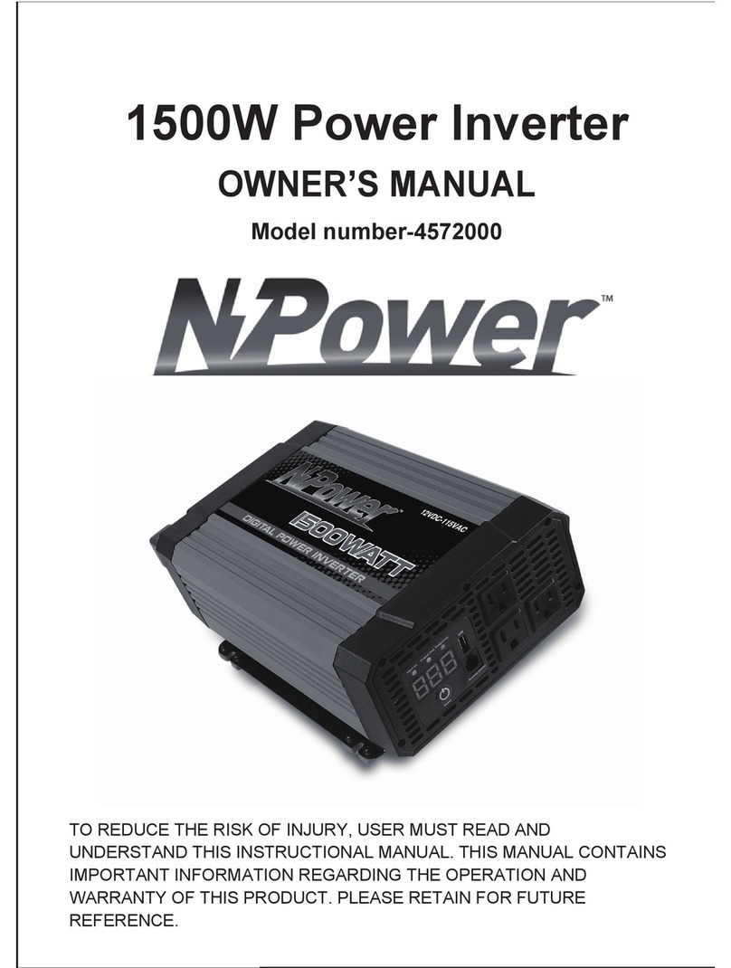
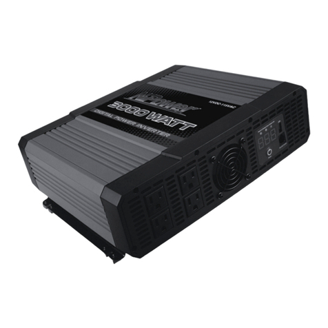
5000W Power Inverter
OWNER’S MANUAL
Model number-4575000
TO REDUCE THE RISK OF INJURY, USER MUST READ AND UNDERSTAND
THIS INSTRUCTIONAL MANUAL. THIS MANUAL CONTAINS IMPORTANT
INFORMATION REGARDING THE OPERATION AND WARRANTY OF THIS
PRODUCT. PLEASE RETAIN FOR FUTURE REFERENCE.

TABLE OF CONTENTS
1. Introduction ........................................................................................... 1
2. Important Safety Information................................................................ 1
3. Protective Features................................................................................ 4
4. Features................................................................................................. 6
5. Installation ............................................................................................ 8
6. Operating Instructions......................................................................... 11
7. Troubleshooting...................................................................................13
8. Specifications ......................................................................................16
9. Warranty ..............................................................................................17

1
1. Introduction
Thank you for purchasing the NPower Digital Power Inverter, a high
performance solution for using household power while on the road.
Connected to the 12 V output in your vehicle, the inverter efficiently and
reliably supplies 115 V/60 Hz AC power with 4000 W continuous output
power for a wide variety of loads, such as all kinds of jacklights, air
conditioners, audio/video systems and tools with power consumption
under 5000 W. It is ideal for operating household appliances on your car,
truck, RV and boat.
The inverter has the safety features such asover input voltageshutdown,
low input voltage shut off,low input voltage alarm, low voltage turn-off
resume, over heating shut off, overload shut off short circuit
protection. The digital display will
errors. The unit is not designed to be
directlyreadout output power and
waterproof.
2. Important Safety Information
For safe and optimum performance, the inverter must be installed and
used properly. Carefully read and follow the guidelines in this guide and
give special attention to the CAUTIONand WARNING statements.

CAUTION: Instructions provide information that could
damage your inverter or equipment connected to it!
WARNING: Instructions provide information on conditions
that could result in personal injury or loss of life!
Warning!Shock hazard!Keep away from children!
Warning!
The inverter produces the same potentially lethal AC power as normal
household outlets. It is suggested that you treat it as a normal AC outlet.
Warning!
The case to the unit may become very warm under high power operation.
Be surethat there is at least 2” (5cm) of unblocked air spacearound the
entire surface of the inverterat alltimes. During use,do not place
materials that could be damaged by heatnear the unit.
Warning!
Do not operate the unit nearflammable fumes or gases, such as in the
cabin of a gasoline powerboat, or near propane tanks.
Warning!
Do not operate the unit in an enclosed area that contains automotive type
lead-acid batteries. This type of battery emits explosive hydrogen gasthat
can be ignitedbysparks.
2

Warning!
Always make all AC connections before making DC connections or the
components built into the inverter can become energized producing an
electrical shock hazard. Never work on the AC wiring without first
physically disconnecting the DC connections.
Warning!
If connected with loads of over 2000 W, two setsof same size wirings
must be connected to the same batteryor the connected batterykit. And it
may damage the inverter if using oneset of wiring only or connecting two
sets of wirings to different batteries separately!
Caution!
Do not connect the unit to live AC power circuits or there may be damage
to theinverter. Do not connect any AC device which has its neutral
conductor connected to ground which connect to the unit.
Caution!
Some chargers for small nickel-cadmium batteriescan be damaged if
connected to the unit. Do not use the unit on the following items:
Small battery-operated appliances such as flashlights, razors
and nightlights that can be plugged directly into an AC outlet to
recharge.
Certain battery chargers for battery packs used in hand power
tools. These chargers will have a warning label indicating that
dangerous voltagesare present at the battery terminals.
3

Caution!
Connect the unit tobatterieswith a normal output of 12 V DC only. A 6 V
battery’s voltage is too low, and a 24 V battery’s voltage is too high and
will damage the unit.
Additional Safety Guidelines!
•Do not insert anyforeign objectsinto the unit outlets, vents or fan
openings.
•Do not expose the unit to rain, water or any other liquid.
•Do not connect the unit to any utility power distribution systems
or branch circuits.
•Do not use the inverter in temperatures over 104°F(40°C) or
under 32°F (0°C).
Failure to follow these safety guidelines will result in
personal injury and/or the damage to the unit. It may also
void the warranty.
3. Protective Features
Over-input Voltage Shut Off
When the 12 V DC power supply voltage exceeds 15.5 ± 0.5 V, the
inverter will automatically shut down, and the digital display showing
“OUP”.
4

5
Low-input Voltage Shutdown
When the 12 V DC power supply voltage drops below 10.5 ± 0.3 V, the
inverter will automatically shut down, and the digital display showing
“LUP”.
Low-input Voltage Alarm
When the 12 V DC power supply voltage drops below 11 ± 0.3 V, an
audible alarm will sound, and the digital display showing “LUP”.
Over-heating Shut Off
When the internal temperature exceeds the regulated temperature due to
the increaseof ambient temperature, the inverter will automaticallyshut
down,and the digital display showing “LCP”.
When the internal temperature drops below the surrounding air
temperature, the inverter willautomaticallyreturn to normal operation.
Overload Shut Off
When the starting power exceeds the rated power, the inverter will
automatically shut down, and the digital display showing “OLP”.
inverter can’t automatically
restore normal operation: reset to normal
switch.
operation by using manual
Short-circuit Protection
This inverter is equipped with multiple internal fuses.
circuit state, the unit will switch to protective mode, and the digital display
showing “OPP”.
When in over current protection mode, the
When it is in short

4. Features
Figure 1: Digital Power Inverter Front Panel
1. Red LED—Indicates that the consumption of the loads is under 1000
W, and the digigal display showing output power loads in watts.
2. Yellow LED—Indicates that the consumption of the loads is over
1000 W, and the digigal display showing output power loads in
kilowatts.
voltage.
3. Green LED— Indicates the digital display is showing DC input
4. USB Port—Powers and charges USB-enabled devices.
5. Remote Switch Port—Use to connectthe remote ON/OFF switch
via a communication cable.(remote control switch is not included.)
6

6. Power Switch Button— Turn the inverter ON or OFF.
7. Digital Display—Shows input voltage (in volts), output power (in
kilowattsand watts), and error code information. The allowed power
tolerance is 15% (with loads of over 300 W), and the allowed voltage
tolerance is+/- 0.2 V (no load).
8. Cooling Fan and Ventilation Openings— The high-speed cooling
fan protects the inverter from over-heating. Ventilation openings
should bekept clean!
9. 2 GFCI-Protected Outlets—Each GFCI has two AC outlets and is
connected with 20A circuit protector.
10.Two 20A Circuit Protectors
Figure 2: Digital Power Inverter Rear Panel
11. Negative (-) DC terminal—Connects to negative battery cable.
12. Positive (+) DC terminal— Connects to positive battery cable.
13. Chassis Ground Lug
14. Ventilation Openings
15. AC Konckout
7

5. Installation
The unit must be operated in an area that meets thefollowing
requirements in order to operate safely and provide optimum
performance:
Description
Dry
Don’t allow water or other liquids to drop or splash on
the unit.
Cool
Ambient air temperature should be between 32°F and
(0°C- 40°C) (the cooler the better within this
range if the ambient temperature is high, the output
power may not reach 4000W before the over
temperature protection occur.)
401 F
o
Ventilated
Leave at least 2” (5 cm) of clearance around the unit
for airflow. Ensure that the ventilation openings are
not obstructed.
Safe
Do not operate the unit in the same compartment as
batteries or in any compartment storing flammable
liquids like gasoline.
Clean Do not operate the unit in an area that is prone to dirt,
8

dust or debris. Especially important if it is in working
condition.
Your Digital Power Inverter supplies max continuous 5000W (5 min)
power with 10000 W of surge power. When you turn on an appliance or a
tool that operates using a motor or tubes, it requires an initial surge of
power to start up. This surge of power is referred to as the “starting load”
or “peak load”. Once started, the tool or appl iance requires less power to
continue operating. This is referred to as the “continuous load” in terms
of power requirements. You will need to determine how much power your
tool or appliance requires to start up and its continued running power
requirements.
The inverter should be connected to your vehicle’s 12Vpower with the
DC cables. We recommend that the equipment or appliance switch be in
the “OFF” position prior to plugging into the AC receptacle of the inverter.
Warning!
Shock hazard!Keep away from children!
Please be sure to remove metal jewelry, such asrings, bracelets and
watchesetc. to avoid accidents!
9

Connecting the inverter:
1) Place the inverter on a flat surface, such ason the vehicle floor.
2) Please make sure that the inverter is shut down.
3) Attach the ringtype connector marked with red to the positive (+)
DC terminal on the power inverter, and attach the ring connector
marked with black to the negative (-) DC terminal.
Caution!
Reversing the polarity will cause damage to the inverter,
which may also void the warranty.
4) Tighten the nut on each DC terminal by hand until it is snug. Do
not over-tighten.
5) Connect the AC equipment.
6) When the power inverter is not in use, disconnect the DC cable
clips fromthe batterytoprevent gradual discharge of battery.
Note: This product does not include DC battery cables. DC
battery cables are sold separately.
Caution!
A loose connection will cause the voltage to drop and may cause the
cables to overheat, resulting in equipment damage or fire.
10

6. Operating Instructions
1) When properlyconnected to a 12 V outletor battery, turn on the
inverter, and the digital readoutwillswitch on and the unit will
deliver AC power to the outlet(s).
2) Plug the AC product(s) you wish to operate into the AC outlet(s)
3) Switch them on, one at a time (Please do not turn on allatthe
same time).
Caution!
If there are one more AC products connecting to the
inverter, turn on the larger power product first.
4) The unit will operate from input voltages ranging from 11.0 V to
15.0 V DC.
As the batteryis used,its voltage beginstofall. When the inverter senses
that the voltage atits DC input has dropped to the range of 10.7 - 11.3 V
DC, an audible alarm sounds, digitaldisplay reads “LUP”. This allows
time for computers or other sensitive devices to be shut down. If the
audible alarm is ignored, the inverter will automatically shut down when
the voltage dropped to the range of 10.2 - 10.8 V DC. When readout
shows “LUP”, it is indicating a fault happening to the unit. This protects
the battery from being over-discharged. Turn off any devices that the
inverter is powering.
When input voltagerises to 11.3 – 11.9 V DC, inverter restores to
normal.
11

Caution!
Most vehicle batteriesare designed to provide short period of very
high current for starting the engine. They are not designed for a constant
“deep discharge”.Constantly operating the unit from a vehicle battery
until the low voltageshut off will affectthe life of the battery. If you are
operating electrical productsfor extended periods of time, you should
consider connecting the unitto a separate deep discharge battery.
Should a defective battery charging system cause the battery voltage
to rise to the range of 15.0 - 16.0 V DC, the inverter automatically shuts
down;readout shows “OUP”
Caution!
Although the inverter incorporates protection against
over-voltage, it may still be damaged if the input voltage
exceeds 16 V.
If an AC product rated higher than 5100 W (or which draws excessive
surge power) is connected, the inverter willshut down, the displaying
readout shows “OLP”.The unit willshut down automatically if the
inverter exceeds a safe operating temperature due to insufficient
ventilation or a high-temperature environment; and the readout will
display “OCP”.The cooling fan is designed by the thermo-controlled
technology.
12

Caution!
Operating time willvary depending on the charge level of the battery, its
capacity and the power level drawn by the particular AC load. With
4000 W load, the operating time is depending on the vehicle battery
capacity. When using a vehicle battery as a power source, it is strongly
recommended to start the vehicle every hour to recharge the battery
before its capacitydrops too low. The inverter can operate while the
engine is running, but the normal voltage drop that occurs during starting
of the engine may trigger the inverter’s lowvoltage shutdown feature.
Caution!
Because the power inverter draws less than 0.5 A when turning on with
no AC product connected, it has minimal impact on battery operating
times.
7. Troubleshooting
PROBLEM CAUSE SOLUTION
Battery is defective Replace battery
Blown fuse Go to a specialist to
check it and help to
replace the fuse
No power, no
indicator
Loosecable
connections
Check the connection to
the battery. Tighten as
required
13

14
AC products connected
are rated at more than
5000W; overload
shutdown has occurred.
Reduceload, use a
product with power rating
less than 5000 W.
Unit is shutdown
with display
showing ”OLP”
AC products are rated
less than 5000 W, but
high starting surge has
caused overload
shutdown.
Use a product with
starting surge power
within the inverter’s
capability (≤10000 W).
Unit is shutdown
with display
showing “LUP”
The voltage input is too
low(alarmsounds). Charge the battery.
Unit is shutdown
with display
showing “OCP”
Inverter is overheated
due to poor ventilation
and has shut down.
Unplug inverter from DC
socket and cool for
15 minutes. Remove
objects covering unit.
Move the invertertoa
cooler place. Reduceload
if continuous operation is
required. Restart.
Inverter runs
small loads but
not large ones.
Lowvoltage battery
.
Charge the battery
.
Water entered
unit. Water entered the unit
.
Disconnect the inverter
and wipe immediately
with adrycloth, or
Unit is shutdown
with display
showing “OPP”
Inverter is short circuit
and has shut down.
Reset to normal
operation by using
manual switch

15
permanentdamage can
occur with liquid ingress.
Alarmsounds.
Low voltage shutdown
or thermal shutdown has
occurred.
Shorten cablesor use
heavier cables. Recharge
battery. Allow unit to
cool. Improve air
circulation around unit.
Locate unit to a cooler
environment. Reduce
load if continuous
operation is required.
Standard
“average-reading” AC
voltmeter used to
measureoutput voltage,
resulting in an apparent
reading 5 to 15 V too
low.
Inverter’s “modified sine
wave” output requires
“true RMS” voltmeter for
accurate measurements.
Measured
inverter output
voltage is too
low.
Batteryvoltage is too
low Recharge battery.
AC product’s power
consumption is higher
than rated.
Use a larger battery to
make up for increased
power requirement.
Batteryis old or
defective Replacebattery.
Batteryrun time
is less than
expected.
Battery is not being Some chargers are not

16
properly charged. able to fully recharge a
battery. Make sure you
use a powerful charger.
Power dissipation in DC
cables.
Use shorter/heavier DC
cables.
8. Specifications
Specificationsare subject to changewithout notice.
AC Output
Continuous AC output power
Max. continuous AC output
power( 5 minutes)
4000 W
5000 W
AC output surge power 10000 W
AC output voltage range 105 V - 125 V AC
Output frequency (nominal) 60 ± 1 Hz
Output waveform Modified sine wave
USB Output
DC output 5 V 500mA
DC Input
Rated DC input voltage 12.0 - 12.4 V DC
Lowbattery alarm 11 ± 0.3 V DC, Audible
Lowbattery shutdown 10.5 ± 0.3 V DC
Lowbattery shutdown resume 11. 6 ± 0.3 V DC

17
High battery shutdown 15.5 ± 0.5 V DC
Fuse 25A fuse ×24
Physical specifications
Dimensions 16.5 x 11.6 x 5.9"
(42 x 29.5 x 15 cm)
Weight 25.96 lb (11.80 kg)
9. Warranty
One Year Limited Warranty Program
NPower warrants this product for one yearlimited against any defects in
materials or workmanship. The defective products will be replaced and
repaired at no charge in either of one year.
This warranty lasts for 12 months fromthe date of purchase at the point
of sale to you. This warrantydoes not apply where the product has been
misused, improperly installed, physically damaged or altered, either
internallyor externally, or damaged fromimproper use.
NPower will repair or replacethe defective product free of charge. Proof
of purchase may be required. Warranty term is not extended if NPower
repairs or replaces a product. NPower owns all parts removed from
repaired products.

18
To qualifyfor the warranty, make sure the product has not been
disassembled or modified without the prior authorization. If you require
warranty service with your product, please return it to the place of
purchase along with a copy of your dated proof of purchase or call
customer service at 800-222-5381 for details.
Table of contents
Other NPower Inverter manuals
Popular Inverter manuals by other brands

Ginlong
Ginlong Solis Installation and operation manual

Stober
Stober POSIDYN SDS 5000 Operation manual

Fischer Panda
Fischer Panda Panda 12 mini PMS Digital installation manual

INVT
INVT XG15KTR Operation manual

Generac Power Systems
Generac Power Systems GUARDIAN SERIES 005870-1 overview

Sensata
Sensata 12/800N owner's manual