Accorroni HR 3.0 User manual

1
FIRST START-UP
MANDATORY FOR
WARRANTY ACTIVATION
REV_05/06/2022
INSTALLATION MANUALHUB RADIATOR PACK CF
High efciency patented integrated hybrid system
in direct exchange heat pump
coolant / water with back-up boiler
to produce domestic hot water, heating
o air conditioning for small and medium users
HUB RADIATOR PACK CF

2
Informazioni tecniche
Technical information
SECTION A - GENERAL INFORMATION
Contains all the information relating to the description of air-water heat pumps and their technical characteristics.
SECTION B - TECHNICAL NEWS FOR THE INSTALLER
It collects all the information and requirements that the installer must observe for the optimal implementation of the system.
SECTION C - USER INSTRUCTIONS FOR USE AND MAINTENANCE
This is the section reserved for the user and contains all the information necessary for proper operation and for periodic checks.
Important notes for consultation
1 For the purposes of a correct and safe use of the appliance, the installer, the user and the maintenance technician, for their respective
skills, are required to observe the indications in this manual.
2 The word ATTENTION is followed by information which, due to their importance, must be scrupulously observed and whose failure to
comply can cause damage to the appliance and / or jeopardize its safety of use.
3 Paragraphs highlighted in bold contain important information, warnings or advice that you should carefully consider.
4 The technical data, aesthetic characteristics, components and accessories shown in this manual are not binding.
The A2B Accorroni E.G. S.r.l. reserves the right to make any changes deemed necessary for the improvement of your product.
- References to laws, regulations or technical rules mentioned in this manual are intended for information purposes only and are to be
considered valid on the date of printing of the same, shown on the last page. The entry into force of new provisions or changes to those
in force will not constitute a reason for any obligation of the A2B Accorroni E.G. S.r.l. towards third parties.
- The A2B Accorroni E.G. S.r.l. is responsible for the compliance of its product with the laws, directives and construction standards in
force at time of marketing. Knowledge and compliance with the laws and regulations relating to design of the systems, installation,
operation and maintenance are the sole responsibility, for the respective competences, of the designer,
of the installer and user.
Factory made hybrid system
HUB RADIATOR PACK CF
INDEX
1. MAIN FEATURES.................................................................................................................................................................. 4
1.1 Appliance classication ......................................................................................................................................................... 4
1.2 Certications - CE marking ................................................................................................................................................... 4
1.3 Construction features ............................................................................................................................................................ 4
1.4 Packaging contents .............................................................................................................................................................. 4
1.5 Standard equipment and accessories supplied on request. ................................................................................................ 4
1.6 Field of use ........................................................................................................................................................................... 4
1.7 Safety rules ........................................................................................................................................................................... 4
2. U.E. CONNECTIONS / I.U ................................................................................................................................................... 5
2.1 General provisions ................................................................................................................................................................ 5
2.2 Electrical connections U.E .................................................................................................................................................... 5
2.3 R410A refrigerant piping installation...................................................................................................................................... 5
2.4 Installazione entro i 5 metri ................................................................................................................................................... 6
3. OUTDOOR UNIT INSTALLATION........................................................................................................................................ 7
3.1 General indications ............................................................................................................................................................... 7
3.2 Distances of respect ............................................................................................................................................................. 8
3.3 Roof installation .................................................................................................................................................................... 8
3.4 Elimination of air with the vacuum pump .............................................................................................................................. 8
3.5 Evacuation ............................................................................................................................................................................ 9
3.6 Opening of the valves and refrigerant release relative to the outdoor unit .......................................................................... 9
3.7 Pump Down .......................................................................................................................................................................... 7
3.8 Recovery procedure ............................................................................................................................................................. 9
3.9 Acoustic requirements........................................................................................................................................................... 9
4. NDOOR UNIT INSTALLATION.............................................................................................................................................. 10
4.1 Selection of the installation site for the hybrid system .......................................................................................................... 10
4.2 Assembly procedure ............................................................................................................................................................. 11
4.3 Smoke intake / exhaust system ............................................................................................................................................ 12
4.4 Conguration of the B23 type ue gas intake / exhaust ducts.............................................................................................. 13
4.5 Air intake / ue gas discharge through coaxial ducts with a diameter of 100/60 meters...................................................... 13
4.6 Chimney sweep function....................................................................................................................................................... 14
4.7 Connection to the gas network.............................................................................................................................................. 14
4.8 TSP parameters that can be set from the interface and from the Remote Control.............................................................. 14
4.9 Adaptation to the use of other gases and burner adjustment............................................................................................... 16
4.10 Transformations from METHANE to LPG............................................................................................................................. 16
4.11 Transformations from LPG to METHANE ............................................................................................................................ 16
4.12 Check and adjust the gas valve ........................................................................................................................................... 16
4.13 Testing the boiler ................................................................................................................................................................... 17
4.14 Preliminary check .................................................................................................................................................................. 17
4.15 Maintenance .......................................................................................................................................................................... 17
4.16 Combustion analysis ............................................................................................................................................................. 18
4.17 Decommissioning, disassembly and disposal ...................................................................................................................... 18

3
5. TECHNICAL SPECIFICATIONS INDOOR UNIT / OUTDOOR UNIT HUB RADIATOR PACK CF 3.0 - 7.8....................... 19
5.1 Performance characteristics of outdoor units Booster HUB RADIATOR PACK CF 3.0 - 7.8 .............................................. 19
5.2 Technical data table for domestic hot water withdrawal HUB RADIATOR PACK CF .......................................................... 19
5.3 HUB RADIATOR PACK CF boiler technical data table ........................................................................................................ 20
5.4 Boiler operating data table HUB RADIATOR PACK CF ....................................................................................................... 21
5.5 Booster HUB RADIATOR PACK CF outdoor unit technical data table ................................................................................ 21
5.6 Dimensions of outdoor and indoor unit HUB RADIATOR PACK CF wall-mounted ............................................................. 22
5.7 Indoor unit dimensions HUB RADIATOR PACK CF recessed ............................................................................................. 22
5.8 Hydraulic diagram of the boiler HUB RADIATOR PACK CF ................................................................................................ 22
5.9 Accessories HUB RADIATOR PACK CF .............................................................................................................................. 23
6. CIRCULATOR HUB RADIATOR PACK CF .......................................................................................................................... 25
7. MODALITÀ DI FUNZIONAMENTO HUB RADIATOR PACK CF ......................................................................................... 25
7.1 Heat pump only operation ..................................................................................................................................................... 25
7.2 Hybrid operation, heat pump with integration boiler ............................................................................................................. 25
7.3 Boiler only operation (EMERGENCY) .................................................................................................................................. 25
8. DIGITAL CONTROL UNIT..................................................................................................................................................... 26
8.1 Display .................................................................................................................................................................................. 26
8.2 Display icons ......................................................................................................................................................................... 26
8.3 Function of the keys .............................................................................................................................................................. 26
8.4 Access to parameters ........................................................................................................................................................... 27
8.5 View and change the set point .............................................................................................................................................. 27
8.6 Main alarms............................................................................................................................................................................ 28
8.7 Table of faults causes remedies............................................................................................................................................. 28
9. PARAMETER TABLES.......................................................................................................................................................... 30
9.1 Sub-menu selection .............................................................................................................................................................. 30
9.2 Conguration parameters ..................................................................................................................................................... 30
9.3 Digital control unit wiring diagram ......................................................................................................................................... 34
10. WARNINGS .......................................................................................................................................................................... 35
9.1 Qualication of the installer ................................................................................................................................................... 35
9.2 Preliminary information ........................................................................................................................................................ 35
9.3 Transport and handling ......................................................................................................................................................... 35
9.4 Using the instructions ........................................................................................................................................................... 35
9.5 General system checks ........................................................................................................................................................ 35
11. START-UP.............................................................................................................................................................................. 35
11.1 Initial start-up checks ............................................................................................................................................................ 35
11.2 Put in action .......................................................................................................................................................................... 35
12. REPAIR - COMPONENT REPLACEMENT.......................................................................................................................... 35
12.1 Refrigerant circuit .................................................................................................................................................................. 35
12.2 System drying and vacuum ................................................................................................................................................... 36
12.3 Circuit cleaning ...................................................................................................................................................................... 36
12.4 Refrigerant charge ................................................................................................................................................................ 36
12.5 Check for overheating .......................................................................................................................................................... 36
13. EXTERNAL PROBE KIT....................................................................................................................................................... 36
13.1 Wall mounting of the external probe ..................................................................................................................................... 36
14. HYBRID SYSTEM CLIMATE MANAGEMENT..................................................................................................................... 37
14.1 Example of operation with external climatic probe hybrid system HUB RADIATOR PACK C ............................................ 37
14.2 Operating parameter settings procedure ............................................................................................................................. 37
14.3 Climate management procedure .......................................................................................................................................... 38
14.4 Integration management procedure ..................................................................................................................................... 38
15. ELECTRICAL CONNECTION DIAGRAMS........................................................................................................................... 39
15.1 HUB RADIATOR PACK C wiring diagram 3.0 ...................................................................................................................... 39
15.2 HUB RADIATOR PACK C wiring diagram 7.8 ...................................................................................................................... 40
16. HYDRAULIC DIAGRAMS...................................................................................................................................................... 41
16.1 Example of heating and DHW production system with patented HUB RADIATOR PACK C system .................................. 41
16.2 Application example HUB RADIATOR PACK C 3.0 / 20 ...................................................................................................... 41
17. MAINTENANCE..................................................................................................................................................................... 42
17.1 Cleaning the exchangers ...................................................................................................................................................... 42
17.2 Annual check ........................................................................................................................................................................ 42
18. GENERALITY........................................................................................................................................................................ 42
18.1 Using the instructions............................................................................................................................................................. 42
18.2 Use improper recommendations .......................................................................................................................................... 42
19. FIRST START-UP REQUEST............................................................................................................................................... 43
19.1 Attachments A - B ................................................................................................................................................................. 45
20. FIRST START-UP BOARD.................................................................................................................................................... 46
21. MODULE 87........................................................................................................................................................................... 49

4
1.MAIN FEATURES
1.1 CLASSIFICATION OF EQUIPMENT
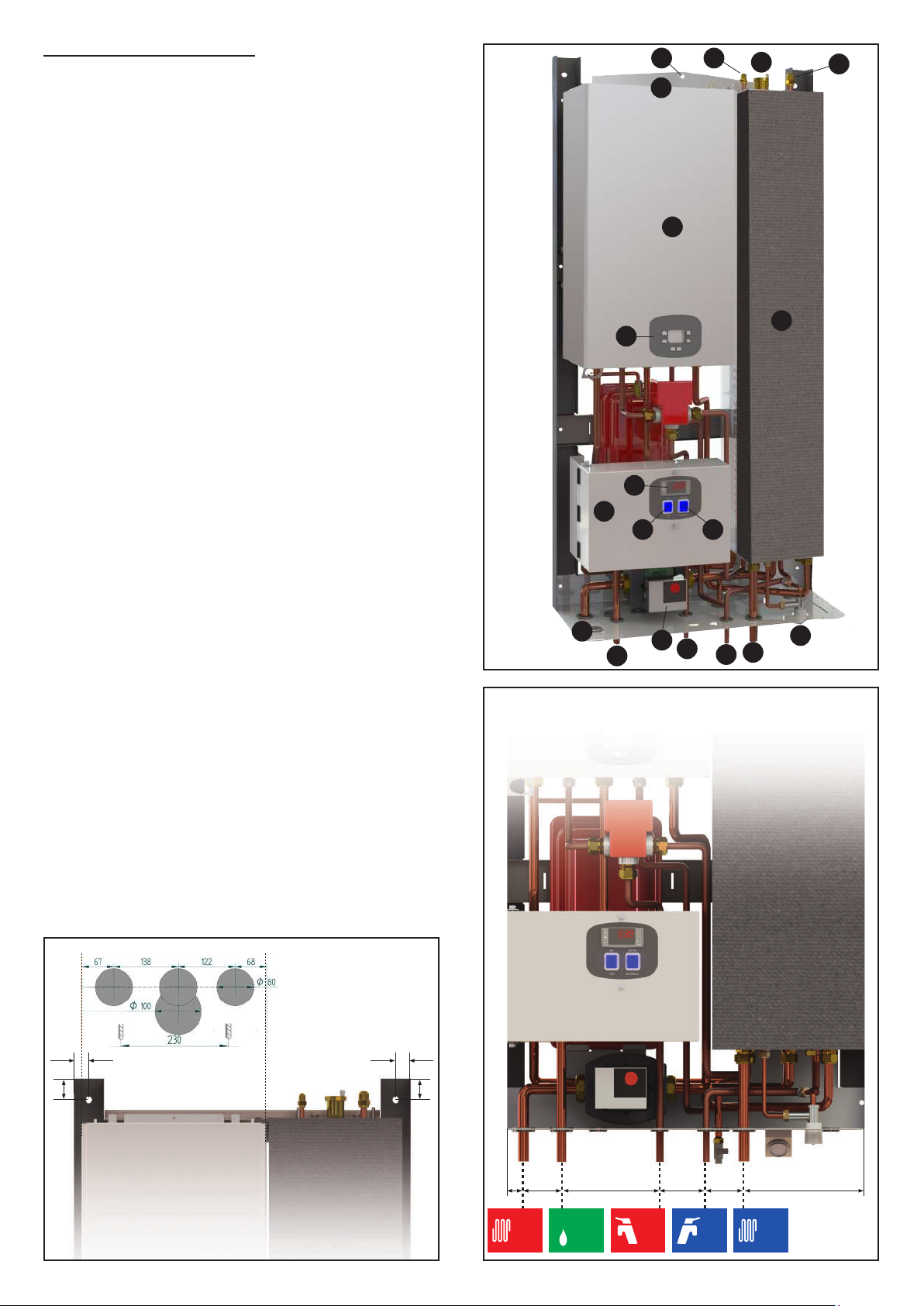
The fundamental elements that make up the HUB RADIATOR
PACK CF system are:
1) Electronically controlled external moto-evaporator dened
as: “Split air-water heat pump”, fed by R410A refrigerant uid with
ON - OFF compressor model Booster HR 7.8 (HUB RADIATOR
PACK CF 7.8) or HR 3.0 (HUB RADIATOR PACK CF 3.0).
2) Indoor unit consisting of a modulating condensing boiler from
2.9 to 24.9 kW which works as a support to the heat pump and
a 48-liter closed vessel accumulator of technical water inside
which all the copper exchangers are positioned both for the
production of DHW and for the heat exchange with the external
motor-evaporator.
1.2 CERTIFICATIONS - CE MARKING
The patented HUB RADIATOR PACK CF system complies with
directives 97/23 / EC and 98/37 / EEC.
They also comply with the provisions of the following directives:
73/23 / EEC, 89/336 / EEC, as amended by directive 93/68 /
EEC.
The indoor unit of the HUB RADIATOR PACK CF hybrid system
has been designed to be installed only and exclusively inside
buildings or on a special external niche that is thermally insulated
and protected from atmospheric agents.If this indication is not
respected, any type of warranty is void.
1.3 CONSTRUCTION FEATURES
All the machines are equipped with a microprocessor for
controlling and adjusting the operation and safety of the units.
Thanks to the patented direct exchange condensers, the products
of the HUB RADIATOR PACK CF series are able to reach high
standards of energy efciency and SCOP.Altre caratteristiche
costruttive:
- the cabinet covering the outdoor unit is made for everyone
the models in sheet metal pre-painted with epoxy powder.
The compressor compartment is completely isolated from the
compartment refrigerant air exchanger; this allows you to
protect the better the electromechanical components;
- the compressor is of the high efciency rotary type, working
with R 410A refrigerant, mounted on supports anti-vibration
rubber bands, driven by a single-phase electric motor for all
models;
- the air / refrigerant gas exchanger
it is made with copper pipes and blocked aluminum ns by
mechanical expansion of the pipes, with high heat exchange
surface;
- the fan unit it consists of a helical fan driven directly by
single-phase asynchronous motor with internal thermal
protection. The fan is equipped with safety protection grid;
- the quick heat exchanger DHW is made of copper
directly immersed in the technical water of the indoor unit
with the FIRST IN - FIRST OUT method, so as to eliminate
the problem of legionella within the accumulation.
- the refrigeration circuit and the links between individuals
components are made of copper tube specic for refrigeration.
The body of lamination, the reverse cycle valve the separator
of liquid;
- the electrical command and control panel is directly
positioned inside the cover cabinet.
- the microprocessor control system with keyboard is
located on the control plate accessible directly on the front of
the cover cabinet, and can be remotely via the appropriate
command and control panel remote, available as an
accessory, to be installed a wall or recessed.
- the indoor unit is supplied complete with all the appropriate
internal copper exchangers, R410A refrigerant gas
connections, DHW connections, air vent jolly valve, safety
valve, lling tap, pressure gauge, electronic circulator, 9-liter
expansion tank, temperature probes, I unload.
1.4 CONTENT OF THE PACKAGING
The device is shipped on wooden pallets, with extruded expanded
polystyrene protections and wrapped in a layer of plastic fabric
with air bubbles.
The identication data of the device are shown both on the label
on the packaging and on the technical data plate applied inside
the cover cabinet. Do not remove the technical data plate for
any reason, as the references it contains are necessary for any
maintenance interventions.
Inside the packaging there is also an envelope containing
this manual and the warranty certicate, which must be
delivered to the owner of the device so that he can keep
them carefully for any future use or for consultation.
1.5 STANDARD EQUIPMENT AND ACCESSORIES SUPPLIED
ON REQUEST
The wide range of standard equipment and accessories available
on request allow optimal exploitation of all the functions of the
machines and system to which they are served.
1.6 FIELD OF USE
The appliances designed and manufactured for heating water
in hydronic air conditioning systems and to produce DHW must
be used only for this purpose, in relation to their technical
specications and performance.
The quality and dimensions of the materials used guarantee a
good life span and are suitable for the operation of the devices
both as a whole and in their individual components, subject
to an installation carried out in a workmanlike manner and
under conditions of mechanical stress. chemical and thermal
corresponding to a suitable use.
ATTENTION! All uses not expressly indicated in this manual
are considered improper and are not permitted; in particular,
the use of the equipment in industrial processes and / or
installation in environments with a corrosive or explosive
atmosphere is not envisaged.
The manufacturer declines any liability for damage to
persons, animals or property resulting from non-compliance
with the instructions in this manual, from modications or
tampering with the product, from installation, adjustment,
maintenance errors and from improper use.
Failure to comply with what is indicated in this manual also
results in forfeiture of the warranty conditions.
1.7 SAFETY RULES
ATTENTION! Installation and maintenance must be carried
out exclusively by specialized and specially authorized
personnel.
The connection to the power supply must be performed in
accordance with current national plant standards.
During installation and maintenance operations, it is always
necessary to operate in conditions of maximum safety,
follow the instructions given in this manual and any warning
labels applied to the product.
Respect the installation and operating limits indicated in
this manual, never modify the internal electrical wiring and
refrigeration pipes, do not modify or disable the safety and
regulation devices.
Before any inspection, maintenance, or anything else
involving access to the internal parts of the appliance,
disconnect the general power supply.
In case of need or clarication for installation and maintenance,
contact a Technical Assistance Center authorized by A2B
ACCORRONI E.G.

5
Connection cable
QE power supply
indoor unit
Section
2.5 mm2 x 3
4.0 mm2 x 3
Models
3.0
7.8
Connection cable
QE power supply
indoor unit
Section
2.5 mm2 x 3
4.0 mm2 x 3
Switch
thermal magneto
Section
16 A curv. D
20 A curv. D
Cable
C-1-2
Section
1,50 mm2 x 3
4.0 mm2 x 3
Cable
Pb3
Section
0,75 mm2 x 4
0,75 mm2 x 4
Table 1 - HUB RADIATOR PACK CF cable specications
2. CONNECTIONS U.E. / U.I.
2.1 GENERAL PROVISIONS
1) The HUB RADIATOR MINI system is designed to work
exclusively with the indoor unit positioned inside
of the building to be heated and the booster outside.
2) During the installation phase it must be carefully checked
that the distance and the difference in height between the 2
units comply with data reported in this manual (Table 4).
3) Before installation, check that the wall is where you
are chosen to position the internal accumulation to be able to
withstand the weight of the accumulation itself and of the water
contained in it.
4) In case of replacement of an existing generator carry out the
cleaning the system and adding a special anti-algae additive.
5) When you choose to install the system HUB RADIATOR MINI,
there is to be taken into consideration the electrical absorption
of the outdoor unit. Then arrange all the necessary works to
adapt the electrical system (meter, cable section, switches
circuit breakers, etc.) to ensure correct operation and a
constant voltage between 220V and 240V in correspondence
with the power cables of the outdoor unit. With voltage below
220V it is mandatory to install one voltage stabilizer able to
guarantee, the voltages allowed above, otherwise all types will
be void warranty.
2.2 ELECTRICAL CONNECTIONS U.E.
Connect the cable to the electrical panel:
1) The connection cable of the indoor and outdoor unit must be of
type H07RN-F.
2) Lift the electrical box panel and remove the screws, then
remove the cover.
3) Connect the cables according to the markings. Connect the
cable to the outdoor unit:
4) Remove the cover of the outdoor unit.
5) Connect the terminal cables according to the numbers on the
unit terminal block, respecting the sections shown in table 1
6) Secure the cables so that they do not come into contact with
parts electric or metal.
2.3 INSTALLING THE PIPES FOR THE REFRIGERANT R410A
The main cause of refrigerant gas leaks is due to a defect in the
are. Carry out the folders correctly, respecting the following
indications:
Table 2 - Diameter of R410A refrigerant connections
___________________________________________________
Model Ø LIQUID Ø GAS
___________________________________________________
3.0 1/4” 3/8”
___________________________________________________
7.8 1/4” 5/8”
___________________________________________________
A) Cut the pipes and the cable (Fig. 1)
- Use pipes with suitable measures for the installed unit (Table 2).
- Measure the distance between the indoor and outdoor unit.
- Cut the pipes to a length slightly greater than
distance measured.
- Cut the 1.5 m electric cable. longer than the length of the tube
Taglio tubazioni Fig. 1
B) Removal of the burr (Fig. 2)
- Completely remove all burrs from the section cross section of
the tube.
- The processing must be performed with the end of the tube
down so that burrs do not fall into the tube.
Burr removal Fig. 2
C) Flaring (Fig. 3)
Remove the nuts xed on the indoor and outdoor unit, insert them
on the pipe and perform the aring and removal of the burrs, as
previously indicated.
Folding Fig. 3
D) Fixing the refrigeration pipes (Fig. 4)
Align the pipes by lubricating the external surface of the pipes in
correspondence with the are. Sufciently tighten the nut using
two wrenches.
Fixing Fig. 4
Precautions
Excessive torque can break the nut or crack the folder. to avoid such
dynamics, use a suitable torque wrench respecting the tightening
torque shown in table 3.
Table 3 - Tightening torque
___________________________________________________
Diameter Tightening torque (N/m)
___________________________________________________
Ø 3/8 42
___________________________________________________
Ø 5/8 65
___________________________________________________
Ø 1/4 18
___________________________________________________
This manual suits for next models
2
Table of contents
Other Accorroni Inverter manuals
Popular Inverter manuals by other brands

BARRON
BARRON EXITRONIX Tucson Micro Series installation instructions

Baumer
Baumer HUBNER TDP 0,2 Series Mounting and operating instructions

electroil
electroil ITTPD11W-RS-BC Operation and Maintenance Handbook

Silicon Solar
Silicon Solar TPS555-1230 instruction manual

Mission Critical
Mission Critical Xantrex Freedom SW-RVC owner's guide

HP
HP 3312A Operating and service manual