LG LG S1C-G3 Series User manual

Monocrystalline Solar Module
LGXXXS1C(W, K)-G3

1
Revisions Table
Date Version Amendments Tech note
2012.08.01 1.0 (1st edition) Establish
2012.11.16 2.0 (2nd edition) Legality check

Safety
The instructions related to safety and use indicated in
the this installation manual are intended for the
prevention of unexpected danger, damage, or failure.
Non-compliance with the instructions may cause
product damage, product failure, and/or serious bodily
injury or death.
①Do not contact electrically active parts of the panel,
such as terminals, without appropriate safety gear.
Contact may result in lethal spark or electric shock.
②Do not use or install if the module is broken or torn.
Failure to comply may result in electric shock.
①Perform all work in dry conditions and use only dry
tools. Do not handle wet panels without appropriate
protection equipment. Failure to comply may result in
accident or death.
②Damaged modules must be treated with safety
protection equipment. Failure to comply may result in
serious bodily injury or death.
③Do not approach the damaged or broken module
unless you are an authorized or qualified expert. Failure
to comply may result in serious bodily injury or death.
①Use proper equipment, connectors, wires and
buttresses for the installation of the module. Failure to
comply may result in product damage, product failure or
bodily injury.
②Installation during rain, heavy wind or snowy day may
result in bodily injury or death.
③Holes in the frame or glass of the module may
decrease the strength of the frame or break the glass.
④Do not touch the glass surface or frame of the solar
module after installation of the module. It may result in
injury or death.
⑤Heavy objects must be kept off of the solar module.
Do not stand on or step on the module. Do not drop
the module. Failure to comply may result in product
damage, product failure or bodily injury.
⑥Do not scratch the coating surface of the frame.
Scratches may decrease the total solar output due to
corrosion of the frame.
⑦Do not artificially concentrate sunlight on the solar
module surface. Failure to comply may result in product
damage or failure.
⑧Do not apply a shock to the junction box of the module
or pull the cable. Do not remove the labels attached to
the module. Failure to comply may result in damage of
the product.
⑨If the installing modules on curved surface, (e. g. arch
type), as shown in the below picture, do not forcefully
modify the module in the installation when connecting it
with the structure. Only install the module in the place
where the structure for the panels has been properly
set up.An improper structure may cause deformation
of the panels. Panels may also be damaged by
unapproved installation methods such as the use of a
crane.
2
Failure to follow any and all of the instructions
contained in this installation manual lead to serious
personal injury, death, property damage, or failure of
the Solar Module to perform to specifications.

Before & After Installation
Before Installation
Please carefully read this manual before installation.
•Contact with electrically active parts of the panels,
such as terminals, may result in burns, sparks and lethal
shock whether the panel is connected or disconnected.
•Panels produce voltage even when not connected to
an electrical circuit or load.
•Solar module installation and maintenance must be
performed by qualified and authorized installer.
•All installation instructions should be read and
understood before performing any installation.
•Do not twist, pull, or scratch the cable attached to the
solar module.
•Do not touch the solar module with bare hands. Failure
to comply may result in a serious burn or injury.
•Do not drop the solar module or place weight on a
solar module.
•Do not disassemble the solar module.
•After installation or repair, check that the solar module
are operating properly.
•In the event a solar module or parts are being replaced
the newly replaced module and parts must have the
same model name and parts as the original solar
module.
•Secure all necessary permits and licenses prior to
installing the solar modules.
•Only qualified and authorized individuals are permitted
to treat electrical parts, when there is a breakage, failure
or damage of the product.
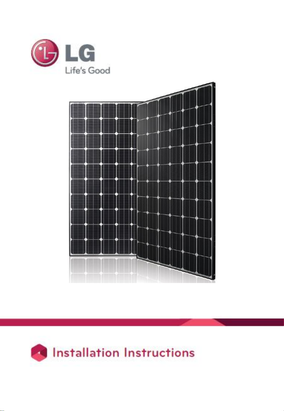
•Do not use or install broken modules; Failure to
comply may result in fire, electric shock, and injury.
•Do not install the module horizontally. Failure to
comply may result in excess dirt or white efflorescence
(glass disease).
•Panels are not intended for use indoors or on moving
vehicles of any kind.
•Reflection from external environments such as snow,
water or other surfaces may increase the power
generated by the panel.
•Industry standard rated specifications are made at
conditions of 1000W/m2irradiance and 25°C (77ºF)
solar cell temperature. Colder temperatures may
substantially increase voltage and power.
•Keep the solar module and system away from children
at all times.
•Keep the module packed in the carton until the time of
installation.
•Keep flammable gasses away from the installation site.
•Do not work alone. Work as part of a team of two or
more people.
•Safety harness use is strongly recommended for
installation.
•Partial shadowing may substantially reduce panel and
system output.
•Care must be taken to avoid low tilt angles which may
cause dirt to buildup on the glass against the frame
edge.
•Dirt build-up on the surface of the panel may cause
active solar cells to be shaded and electrical
performance to be impaired.
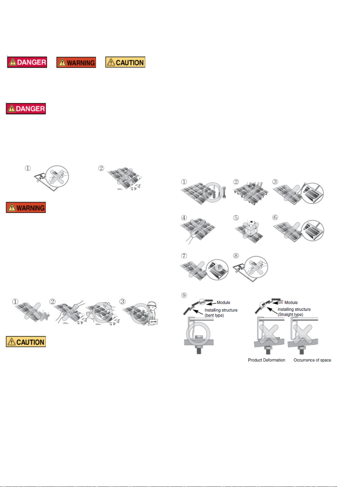
•Always keep the back surface of the panel free from
any foreign objects or structural elements which could
come into contact with the panel.
After Installation
•Plug in the connector tightly and ensure that the wiring
properly works.
•Conduct periodic inspection of the panels for damage
to front glass, back sheet, frame, junction box, or
external electrical connections.
•Check electrical connections for loose connections and
corrosion.
•Removal of dirt from the front glass can increase
output.
•Water, ethanol or a conventional glass cleanser with a
micro-fiber cloth can be used for regular washing or
rinsing of the front glass to remove dust, dirt or other
deposits.
•Aggressive and abrasive cleansers or chemicals such
as alkali chemicals including ammonia based solution
should not be used to clean the module.
•Always wear rubber gloves for electrical insulation
while maintaining, washing or cleaning panels.
•Deposits of foreign material on the frame surface can
be cleaned by using a wet sponge or cloth and dried in
air or by using a clean chamois.
•Perform the wiring work by connecting the connector
and wires to the stand away from the roof or ground.
3

Electrical Installation
Danger
•Avoid all electrical hazards when installing, wiring,
operating and maintaining all panels.
•Do not connect panels that have different electrical
properties or physical configurations in the same
system.
•Match the polarities of cables and terminals when
making the connections; failure to do so may result in
damage to the panel.
•The rating of the over-current device shall not exceed
the maximum series fuse rating marked on the name
plate.
•The panel contains factory installed bypass diodes
located inside the junction box.
•When installing the system, it is recommended to
install a lightning rod to protect the system.
•The junction box should not be opened. Opening the
junction box will void the warranty.
•Panels with a suspected electrical problem should be
returned to LG Electronics for inspection and possible
repair or replacement per the limited warranty provided
by LG Electronics
Electrical Connections
•Shock hazard may occur near the solar modules
electrical connections.
•Modules may be connected in series and/or parallel to
achieve the desired electrical output as long as it is
within the guidelines on the product specification sheet.
•Please use only the same type of modules in a
combined source circuit.
•Do not disconnect the module when it is operating.
Shock hazard may occur near the solar modules
connection means.
Diodes
•All LG modules are equipped with factory installed
bypass diodes. The factory-installed diodes provide
proper circuit protection for the systems within the
specified system voltage.
Series Connection
•The solar modules may be wired in series to produce
the desired voltage output.
•The current of each module connected in series should
be the same.
•The maximum number of series connected
modules can be determined by max system voltage,
the 125% safety factor not explained in
specifications, and the module Voc which can be
checked in “Product Specifications” in this
document.
Do not exceed 80% of maximum system voltage.
•Maximum Module configuration (recommend): refer
to the „Product Specification‟ in this manual.
Parallel Connection
•The solar modules may be combined in parallel to
produce the desired current output.
•When modules are combined in parallel, the total
current is equal to the sum of currents from each
module.
•The voltage of each module connected in parallel
should be the same.
•When connecting plural strings of modules in parallel
every series string or solar module must be fused prior
to combining with other strings.
•Abide with all applicable federal, state, and local codes
for additional fusing requirements and limitations on the
maximum number of solar modules in parallel.
•Maximum parallel strings without proper measures, e.
g. fuse 15 A and/or blocking diode: 1 string.
•Parallel configuration is not limited if proper measures
are taken to block the reverse current flow, e.g. fuses for
the protection of the module and cables from over-
current and/or blocking diodes for prevention of
unbalanced string voltage.
•A multiplying factor is required for increased output of
the PV modules. Under normal conditions, a PV module
is likely to experience conditions that produce more
current and/or voltage than reported at standard test
conditions. Accordingly, the values of Isc and Voc
marked on this PV module should be multiplied by a
factor of 125% when determining component voltage
ratings, conductor ampacities, fuse sizes, and size of
controls to the PV output.
•Follow all national, state and local codes and
standards applicable to overcurrent protection.
4
Diode specification and configuration

Electrical Installation
General Wiring
•LG Electronics recommends that all wiring be double
insulated with a minimum rating of 90°C (194°F).
•All wiring should use a flexible copper (Cu) conductor.
•The minimum size should be determined by the
applicable codes.
•LG Electronics recommends a size no smaller than
4mm2.
Earth Grounding
•The solar modules from LG Electronics meet the
conditions of safety class II. Therefore grounding is not
mandatory. However grounding is recommended. Also,
equipotential bonding must be realized. All work must
be conducted in conformance with all Federal, State,
and local codes and standards.
•Grounding works should be performed by an
authorized installer for the safety and maintenance of
the system in accordance with all national, state and
local electrical codes and regulations and standards.
•Specific information on the solar module dimensions
and location of grounding holes is provided in “Product
Specifications”.
•One M4 stainless steel bolt, one nut, one spring
washer, two flat washers, one cup washer, one star
washer and 12 AWG Cu wires are recommended per
mounting hole.
•Where common grounding hardware (nut, bolts,
washers) is used to attach a listed grounding device,
the attachment must be made in conformance with the
grounding device manufacturer‟s instructions.
•There is an earth hole on the edge of the module
frame. Using this hole, an earth conductor and the
solar module frame may be recommended to be
connected and earthed as the below drawing.
•All screws and nuts shall be tightened to a torque of
4~5 Nm.
•A module with exposed conductive parts is considered
to be in compliance with UL 1703 only when is
electrically grounded in accordance with the instructions
presented below and the requirements of the National
Electrical Code.
The installation instructions shall include:
1. Details for wiring shall comply the NEC Article 690.
2. Details for the grounding method of the frame of
arrays shall comply with the NEC Article 250.
3. CNL model instruction manuals shall also include a
statement that installation shall be in accordance
with CSA C22.1, Safety Standard for Electrical
Installations, Canadian Electrical Code, Part 1.
5

Mechanical Installation
Module Mounting
•The LG Electronics‟ (LGE) Limited Warranty for solar
modules is contingent upon modules being mounted in
accordance with the requirements described in this
section.
•The solar modules are in Application Class A and have
the Safety Class II. Therefore, they can be operated in
systems with 120 V DC and higher. General access is
not restricted.
•Any module without a frame (laminate) shall not be
considered to comply with the requirements of UL 1703
unless the module with hardware that has been tested
and evaluated with the module under this standard or by
a field inspection certifying that the installed module
complies with the requirements of UL 1703.
Site Consideration
LGE solar modules should be mounted in a location that
meets the following requirements.
Operating Temperature
•Maximum Operating Temperature: +90°C (194°F)
•Minimum Operating Temperature: -40°C (-40°F)
Design Strength
•LGE solar modules are certified to basic loads
50lb/ft2 (about 2400 Pa).
Excluded Operating Environments
•The solar modules from LG Electronics can not be
operated in a location where they could come in direct
or indirect contact with salt water or ammonia.
Mounting Methods
General Information
•Select the appropriate orientation to maximize sunlight
exposure.
•Module should not be mounted or stored in a way that
the front/top glass faces downward in order to prevent
water from entering the junction box, which could cause
a safety hazard.
•Clearance between the solar module frames and
structures such as roofs or ground is required to prevent
wiring damage and to allow air to circulate behind the
solar module. The recommended standoff height is a
minimum of 100mm.
•When installed on a roof, the solar module must be
mounted over a fire-resistant roof covering rated for the
application. The fire resistance of the solar module is
class C after ANSI/UL790.
•The solar module is only IEC listed for use when its
factory frame is fully intact.
•Removal or alteration must be done by an authorized
and qualified individual.
•Creating additional mounting holes may damage the
solar module and reduce the strength of the frame.
•We recommend a 6mm gap between module frames
to avoid tension from thermal expansion.
•The fire rating of this module is valid only when
mounted in the manner specified in the mechanical
mounting instructions.
•The module is considered to be in compliance with
UL1703 only when the module in mounted in the
manner specified by the mounting instructions below.
•The solar module may be mounted by using the
following methods: (*Torque:8~12Nm )
Mounting by using frame bolts holes
•Secure the solar module to the structure by using the
factory mounting holes.
•Four M6 stainless steel bolts, four nuts, four spring
washers, and eight flat washers are recommended per
solar module.
•The module may be fastened to a support by using
both the outer and inner bolt holes of the frame.
•Each module should be securely fastened at a
minimum 4 points on two opposite sides.
•Specific information on the solar module dimensions
and location of mounting holes is provided in „Product
Specifications‟.
•Tighten the bolt securely by using the combination
shown above. Place the spring washer between the Flat
washer and Nut.
Mounting by using clamps
•The module may be fastened to a support by using
clamps on both the long edge and the short edge of the
modules.
•Specific information on the solar module dimensions
and location of clamping is provided in „Product
Specifications‟.
Module frame
Bolt
Flat washer
Flat washer
Spring washer
Nut
Support
6

Mechanical Installation
Use four clamps on the short frame and
two clamps at the center of long frame.
Use four clamps on the short frame.
This installation is allowed in the following cases:
1. Slope roof: If module is installed parallel to the rooftop.
2. Flat roof: If installed with an additional stand such as
wind shield or deflector.
Use four clamps on the long frame.
Use four mounting holes on two opposite sides.
Mounting Type
Clamping Type
(Long Side)
Clamping Type
(Short Side)
LGXXXS1C(W,K)-G3
Clamping Range
(230mm)
270mm 270mm
7
Clamping Range:
From module Edge
to 120mm
Clamping Range:
From module Edge
to 270mm
Center ±100mm
Center ±100mm
This method is not tested by IEC / UL.

Product Specifications
- Electrical and Mechanical Properties
(Rated electrical characteristics are within 10 percent)
Standard Test Condition(STC) : Irradiation 1,000W/m2, Cell temp. 25℃, 1.5AM
Certifi
cates
Electrical Properties
Mechanical Properties
Other
Module Series
Model Name
IEC61215 Ed.2, IEC 61730,
Safety Class II, CE, ISO9001
Pmax at STC
Power Tolerance
Voc at STC
Isc at STC
Vmpp at STC
Impp at STC
NOCT
Temperature
Coefficient of Pmax
Efficiency Reduction
From 1000 to 200 W/m2
Max. System voltage
Max. No. of modules in series
Connector
Length
Width
Height
Weight
Max. Series fuse
W
%
V
A
V
A
0C
%/K
%
V
mm
mm
mm
kg
A
LGXXXS1X-G3
LG240S1C-G3
Yes
240
3%
37.96
8.42
30.37
7.91
46.0+2
-0.420
<4.5
600
12
MC4
1640
1000
35
16.8
15
LG245S1C-G3
Yes
245
3%
38.11
8.52
30.57
8.02
46.0+2
-0.420
<4.5
600
12
MC4
1640
1000
35
16.8
15
LG250S1C-G3
Yes
250
3%
38.26
8.62
30.77
8.13
46.0+2
-0.420
<4.5
600
12
MC4
1640
1000
35
16.8
15
LG255S1C-G3
Yes
255
3%
38.41
8.72
30.97
8.24
46.0+2
-0.420
<4.5
600
12
MC4
1640
1000
35
16.8
15
LG260S1C-G3
Yes
260
3%
38.56
8.82
31.17
8.35
46.0+2
-0.420
<4.5
600
12
MC4
1640
1000
35
16.8
15
LG265S1C-G3
Yes
265
3%
38.71
8.92
31.37
8.46
46.0+2
-0.420
<4.5
600
12
MC4
1640
1000
35
16.8
15
LG240S1K-G3
Yes
240
3%
37.96
8.42
30.37
7.91
46.0+2
-0.420
<4.5
600
12
MC4
1640
1000
35
16.8
15
LG245S1K-G3
Yes
245
3%
38.11
8.52
30.57
8.02
46.0+2
-0.420
<4.5
600
12
MC4
1640
1000
35
16.8
15
LG250S1K-G3
Yes
250
3%
38.26
8.62
30.77
8.13
46.0+2
-0.420
<4.5
600
12
MC4
1640
1000
35
16.8
15
LG255S1K-G3
Yes
255
3%
38.41
8.72
30.97
8.24
46.0+2
-0.420
<4.5
600
12
MC4
1640
1000
35
16.8
15
LG260S1K-G3
Yes
260
3%
38.56
8.82
31.17
8.35
46.0+2
-0.420
<4.5
600
12
MC4
1640
1000
35
16.8
15
8
- Dimensions of Modules
LGXXXS1C(W,K)-G3
Long side frame Short side frame
Cross-sectional drawings
Unit: mm / in.

Disclaimer of Liability / Disposal
Disclaimer of Liability
•By beginning the installation process the installer
represents the he/she has read and completely
understands this Installation Manual.He/She further
represents if he/she had any questions regarding this
installation manual he/she would have contacted LG
with any questions or concerns.
•By installing an LG Solar module, I discharge, and
covenant not to sue LG, its affiliated companies,
successors, or assigns, its administrators, directors,
agents, officers, volunteer and employees, other
participants in any activity connected to installation,
operation, or service of LG Solar Modules, and if
applicable, from all liabilities, claims, demands, losses,
or damages on my account caused or alleged to be
caused in whole or in part by the negligence of the LG
its affiliated companies, successors, or assigns, its
administrators, directors, agents, officers, volunteer and
employees.
Disposal
•Please contact us, if you have any queries related to
the disposal or recycling of solar modules from LG
Electronics.
Transporting and Storage
•Do not loosen the banding, when the module is
transported by truck, ship and etc. In case of loose
banding, the module will be shaken, which may cause
damage.
•Do not stack more than three pallets. Severe stacking
can cause stress to the module and may cause product
damage.
9

LG Electronics U.S.A Inc.
1000 Sylvan Ave, Englewood Cliffs, NJ 07632
http://www.lgsolarusa.com
This document is subject to change without notice.
LG, LG logo and Life's Good are trademarks of LG Electronics, Inc. worldwide. Trademarks and
intellectual properties of LG Electronics, Inc. are protected by international copyright laws.
Document : II-G3-UL-V2-EN-201211
10
This manual suits for next models
13
Table of contents
Other LG Inverter manuals

LG
LG SIMs 2.0 User manual

LG
LG LG N3K-V6 Series User manual

LG
LG LG A1C-V5 Series User manual

LG
LG N2T-A5 Series User manual

LG
LG RESU10H Prime User manual

LG
LG N1T-V Series User manual

LG
LG ACAH020HETB Installation instructions

LG
LG LGXXXN2W-L5 User manual

LG
LG SLH-G1 Series User manual

LG
LG ESS Home 10 User manual
Popular Inverter manuals by other brands

Champion Global Power Equipment
Champion Global Power Equipment 200964 Operator's manual

NewMar
NewMar 48-1U-2000RM user manual

Lunt Solar Systems
Lunt Solar Systems LS80THa quick start guide

Xantrex
Xantrex PROWATT SW SW 1000 owner's guide

Midea
Midea MSMABU-09HRDN8-QRD0GW Service manual

Tronic
Tronic 86620 operating instructions