NSK iClave Plus User manual

Rev. 1
Date: June 2015
plus
Water Steam Sterilizer –Class B
OPERATION MANUAL

The iClave Plus complies fully with EN13060, and the built-in parameters have properly set by the manufac-
turer in order to warranty effective sterilization if proper loading conditions are followed.
Please, read carefully this manual before using the machine; an improper utilization of the sterilizer should
carry on defective sterilization with unattended consequences.
In case of doubt or questions, please call the agent.
Thanks for the confidence given.
All rights reserved
No portion of this publication can be printed, transmitted, rewritten, stored in a data recovery system,
translated in any foreign or computer language, in any form or through any devices, without written
consent by NSK.
Information in this manual is subject to change without any warning or prior notice by NSK and does not represent a
commitment for the vendor.
is a trademark of NSK
.
info@nsk.fr
www.nsk.fr
DENTAL X S.p.A.
Via Marzotto 11
36031 Dueville (VI) Italy
Tel. +39 0444 367400
Fax +39 0444 367436
http://www.dentalx.it

1
TABLE OF CONTENTS
1. GENERAL......................................................................................................................................2
1.1 INTRODUCTION ..................................................................................................................................2
1.2 CONFORMITY TO EUROPEAN DIRECTIVES.....................................................................................2
1.3 PACKAGE DIMENSIONS AND WEIGHT.............................................................................................3
1.4 UNPACKAGING ...................................................................................................................................3
2. FAMILIARIZATION........................................................................................................................4
2.1 OVERALL DIMENSIONS......................................................................................................................4
2.2 USABLE SPACE IN THE CHAMBER...................................................................................................4
2.3 SAFETY FEATURES............................................................................................................................5
2.4 PRECAUTIONS....................................................................................................................................6
2.5 FRONT AND REAR VIEW....................................................................................................................7
2.6 STANDARD ACCESSORIES ...............................................................................................................8
2.7 TECHNICAL SPECIFICATIONS...........................................................................................................8
2.7.1 Environment operating conditions .......................................................................................8
3. INSTALLATION.............................................................................................................................9
3.1 BASIC REQUIREMENTS .....................................................................................................................9
3.2 GETTING STARTED ..........................................................................................................................10
3.3 NOTES ABOUT ALTITUDE COMPENSATION..................................................................................11
4. OPERATING INSTRUCTIONS....................................................................................................12
4.1 FRONT PANEL COMMAND/SIGNALING...........................................................................................12
4.2 USB MEMORY CONNECTION...........................................................................................................14
4.3 RUNNING A STERILIZAZION CYCLE...............................................................................................15
4.3.1 Available sterilization cycles ..............................................................................................15
4.3.2 Starting a sterilization cycle ...............................................................................................16
4.4 STOPPING THE CYCLE ....................................................................................................................17
4.5 TOPPING UP AND DRAINING THE WASTE WATER TANK ............................................................18
4.5.1 Topping up the main tank ..................................................................................................18
4.5.2 Draining the waste water tank............................................................................................18
5. PROGRAMMING .........................................................................................................................19
SETUP MENU.............................................................................................................................................19
6. MAINTENANCE...........................................................................................................................21
6.1 AUTOMATIC PERIODIC CLEANING CYCLE ....................................................................................21
6.2 CLEANING THE INSTRUMENTS BEFORE THE STERILIZATION ...................................................21
6.3 CLEANING/REPLACING THE WATER INLET FILTER.....................................................................22
6.4 REGULAR STERILITY TESTS...........................................................................................................22
6.4.1 Porous load test (B&D)......................................................................................................22
6.4.2 Vacuum Test......................................................................................................................22
7. TROUBLESHOOTING.................................................................................................................23
7.1 INITIAL AUTO-TEST ..........................................................................................................................23
7.1.1 Water quality check ...........................................................................................................23
8. ALARMS ......................................................................................................................................24
8.1 GENERAL...........................................................................................................................................24
8.2 WARNING MESSAGES .....................................................................................................................24
8.3 PRE-WARNING ALARMS..................................................................................................................25
8.4 ABORTED CYCLE ALARMS..............................................................................................................25
8.5 CLASS B ADDITIONAL ALARMS.......................................................................................................26
9. CONNECTIONS...........................................................................................................................27
9.1 CONNECTION TO AN EXTERNAL PRINTER....................................................................................27
9.2 CONNECTION TO A COMPUTER.....................................................................................................28
APPENDIX : SERVICE BOOK

2
1. GENERAL
1.1 INTRODUCTION
Object of this manual is to supply instructions for the operators in order to allow:
correct installation
proper maintenance of the sterilizer
The machine must be installed and operated according to the procedures described in this manual.
The user is responsible for what concerns the fulfilment in the legal subject concerning installation and opera-
tion of the sterilizer.
If the machine is not correctly installed and operated or the appropriate maintenance is not carried out, the
manufacturer cannot be considered responsible for any possible breaks and malfunctions.
Please, check for the packing integrity and no evident damages or missing parts (see delivery note).
IN CASE OF DAMAGES OR MISSING PARTS, PLEASE IMMEDIATELY INFORM AND IN DETAIL
THE FORWARDER, NSK AND ITS AREA AGENT.
1.2 CONFORMITY TO EUROPEAN DIRECTIVES
The sterilizer manufactured by Dental X for NSK complies with the electromagnetic compatibility standards in
conformity with the Medical Device Directive 93/42/CEE and with the norm EN 13060.
This equipment has been developed and manufactured using high quality material that can be recycled and
reused.
This symbol means that electrical and electronic equipment, at the end of their lifetime,
must be disposed separately from the household waste. Dispose this unit by carrying it to
the local collection/disposal centre. Sanctions are applied in case the regulations concern-
ing waste disposal are not met.
Help us to preserve the environment in which we live!

3
1.3 PACKAGE
DIMENSIONS
AND WEIGHT
Total weight: 58 Kg
Store the package for possible future shipment.
1.4 UNPACKAGING

4
2. FAMILIARIZATION
2.1 OVERALL DIMENSIONS
2.2 USABLE SPACE IN THE CHAMBER
Diameter: 240 mm
Depth: 384 mm
Capacity: 17,5 l
Useful dimensions per tray: 315 x 214 mm (x 2),
315 x 168 mm (x 2)
Useful tray volume: 10 l
Net weight: 47 Kg
Full load weight: 58 Kg

5
2.3 SAFETY FEATURES
The sterilizer features several devices that assure the full safety for the operators.
Door with dual lock control
An electromechanical device allows the door to be opened only if the following conditions are met:
- unit power supplied and turned on
- no current alarms
- internal pressure not dangerous for the operator
For further safety, to unblock the door at the end of cycle or in case of alarm it is necessary to press the
Start/Stop button.
Attention: If the equipment is turned off with the door open, do not apply force on
the handle to try closing the door. To close it, the equipment must be on.
Protection against overpressure –safety and decompression valves
Safety valve - it takes over when the pressure inside the chamber exceeds the value of 2,55 bar. To
verify the efficiency of the valve, when the unit is cold and switched off, unscrew the black cap of the
valve, when a “click” is heard pull it gently : you have to feel that the cap is free to move. The valve can
not be adjusted or serviced for safety reasons. Follow the maintenance program described in the ap-
pendix SERVICE BOOK to assure the safety of the unit.
Decompression valve –it takes over when the pressure inside the chamber exceed the value of 2,4 bar;
an acoustic signal warns the operator and the display shows the message ALARM 10.
Overheating protection
The temperature inside the chamber is programmed so as not to exceed the limit of 142 °C; in case of fault,
a further protection takes over to prevent the temperature from rising over 150 °C.
Blackout protection
In case of power blackout during the sterilization cycle, the pressure inside the chamber is completely re-
leased to the drain valve. On power supply restore, the display will show the message BLACK OUT.
Automatic switch off
Elapsed 30 minutes from the end of the cycle without opening the door or activating a front panel button, the
unit will automatically switch off.
This function is not operating if no sterilization cycle has been carried out and completed.

6
2.4 PRECAUTIONS
The international norms concerning safety and sterilization process defines the following figures:
OPERATOR: the person operating the unit to achieve the expected result.
RESPONSIBLE AUTHORITY: person or group responsible for the use and maintenance of the unit, he
or she also has to make sure that:
- all personnel who operate or maintain the equipment are trained in its operation and in its safe use.
- there is regular training of all personnel concerned with the operation and maintenance of the
equipment, including emergency procedures for any toxic, flammable, explosive or pathogenic ma-
terial released into the environment.
- Records of attendance at training are maintained, and evidence of understanding demonstrated.
The purpose of this manual is to provide suitable use instructions for both figures: however it does not
give instructions concerning the STERILIZATION PROCEDURE and the cautions to be followed to pre-
vent contamination of instruments and/or personnel using the unit that is a assignment of the
RESPONSIBLE AUTHORITY of the practice.
We wish to point out the following risks:
The sterilization is a process that works by means of water steam under pressure and high temper-
atures; when the load is removed from the sterilization chamber always use tools and wear person-
al protections suitable for handling hot instruments.
On opening the sterilizer, especially in case the cycle has been aborted, a small quantity of hot wa-
ter steam or condensate can be released in the environment; be careful when opening the door.
If the condensation cycle is not brought to an end, the load, the trays and the tray support as well as
the chamber inner space are ALWAYS to be considered as potentially contaminating elements, as
long as a subsequent sterilization cycle has not been successfully completed.
The water (waste) contained in the recovery tank is to be regarded as biologically contaminating,
therefore when this tank is emptied, suitable precautions should be taken. The disposal of recovery
water needs to be done in accordance with the national or local regulation. Check the integrity of
the draining pipe before its use.
To prevent cross contaminations during the loading and unloading steps, open the door with clean
hands or wear uncontaminated gloves to avoid contaminating the door handle, do not use gloves
worn during the instruments decontamination step for this operation; when the sterilized instruments
are removed from the chamber, always use uncontaminated gloves.
In case of contact with hot water, steam or contaminated materials rinse with fresh water and seek
for medical help.
SYMBOLS
On the panels of the unit and in this manual, potential hazards and the parts that can be dangerous at high
temperatures, are marked with this symbol:
WARNING: instruments and chamber are very hot
Contamination risk
CAUTION, risk of danger
Documentation needs to be consulted
Read carefully this user manual because wrong use may expose the user to health risks.
This symbol indicates the presence of additional important notes about the use.
The water steam sterilizer is designed to be used for the sterilization of reusable medical instruments that can
be steam sterilized in a range of temperatures between 121°C and 135°C; any attempt of sterilizing instru-
ments that are not fit for undergoing this process can result in hazard for the operator: it can also lead to po-
tentially serious faults and damage the sterilizer’s safety mechanisms.
The unit is not to be used to sterilize liquids and flammable materials.
The unit is designed for indoor use only.
Do not use in presence of anesthetic or flammable gas.
To avoid an excessive level of humidity, properly air the room where the unit is installed.

7
2.5 FRONT AND REAR VIEW
Water outflow filter
Chamber water inlet
Door
Door handle
Control panel
Main (fresh) water tank feeding point
Bacterial filter
Door gasket
Quick connector for fresh water tank drain
Quick connector for waste water tank drain
Water inlet filter
Temperature sensor
Air line filter
Safety valve connection
Safety valve
Automatic draining of
used water tank (option):
max flow 20 ml/minute,
water T < 70°C
Heat exchanger
Power supply switch
Power supply
Printer interface
(option)
AC Fuses
Vent hole for waste
water tank
PC interface
USB port
ID plate
8
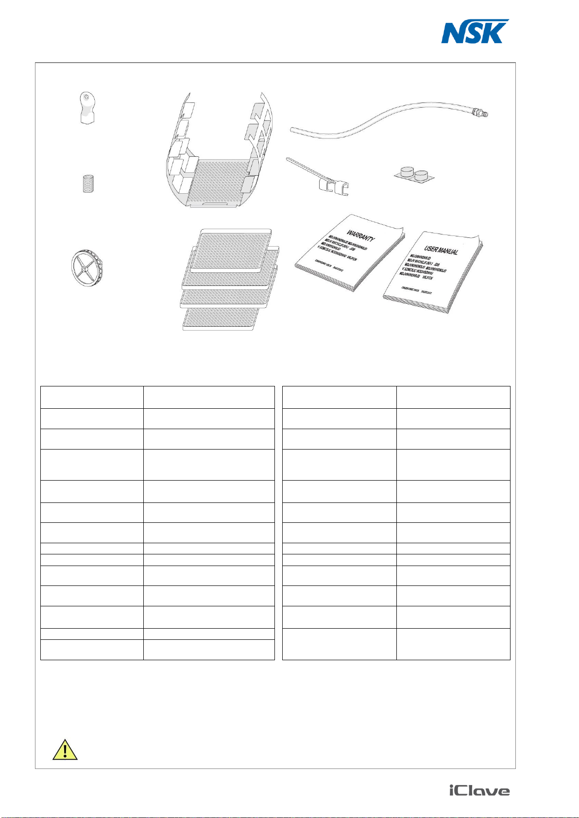
2.6 STANDARD ACCESSORIES
To make the warranty active it is necessary that a copy of the supplied Unit Passport is sent, through
the agent, to the manufacturer; for want of this the warranty will decline.
2.7 TECHNICAL SPECIFICATIONS
2.7.1 Environment operating conditions
The sterilizer is designed to operate in environments with temperature between 3 °C and 40 °C, relative hu-
midity <95%, atmospheric pressure from 750 mBar to 1050 mBar and altitude between 0 and +2000m.
Chamber dimensions
Ø = 240 mm
Depth = 384 mm
Auto-switching-off
elapsed 30’ from the end of a
cycle and without any action
Chamber capacity
17,5 l
Dual water tank
4 liters each (waste and
fresh water tanks)
Maximum load
4 kg (solid)
1,5 kg (porous)
Bacterial filter
0.3 µm al 99.97 %
Warming-up time
20’ from room temperature
10’ with pre-heated chamber
Clock battery
(may be replaced only by au-
thorized service)
Varta CR2032
Sterilization time
from 3’ to 90’ depending on the
selected cycle
Transmitted heat
in environment
0,22 J/h at 23°C
Drying time
from 6’ to 14’ depending on the
selected cycle
Sound emission
52 dB/A at 1 m
External dimensions
443 x 590 x 428 mm
(L x D x H)
Working cycle
continuous
Net weight
47 Kg
Pollution grade
2
Power supply voltage
230 Vac
Transient overvoltage
II
Frequency
50 / 60 Hz
Water conductivity
monitoring
yes
Max consumption
1920 W
Maximum volume available
on the trays
10 l
Average consumption
1000 W
Maximum chamber
temperature
135°C (-0/+2°C)
Standby consumption
10 W
Safety valve
working pressure
2,55 bar
AC Fuses
2 x 12,5A T (type 6.3 x 32 CT ) -
IEC 127
NEVER USE IN PRESENCE OF FLAMMABILE OR ANAESTHETIC GAS.
Tray rack (P/N 105078)
Operating Manual
Warranty paper
Cleaning tabs
Bacterial filter
(P/N 021008)
(+ 1 pcs extra)
Water filter
(P/N 105320)
(+ 2 pcs extra)
Filter spanner
(P/N 105228)
2+2 Trays
(P/N 105076 - 105077)
Tray holder
(PN/ 105619)
Drain tube
(P/N 119001)
9
3. INSTALLATION
3.1 BASIC REQUIREMENTS
1. Check that the mains voltage of your electrical installation
matches the value indicated on the equipment plate, the
electrical socket is capable to supply at least 14A and is
provided with an efficient earth connection. In case the in-
stallation makes inaccessible the power supply switch, pro-
vide for a proper electrical breaker.
The manufacturer will not be responsible
for damages to people or things caused
by an unsuitable electrical installation or
missing of the ground connection.
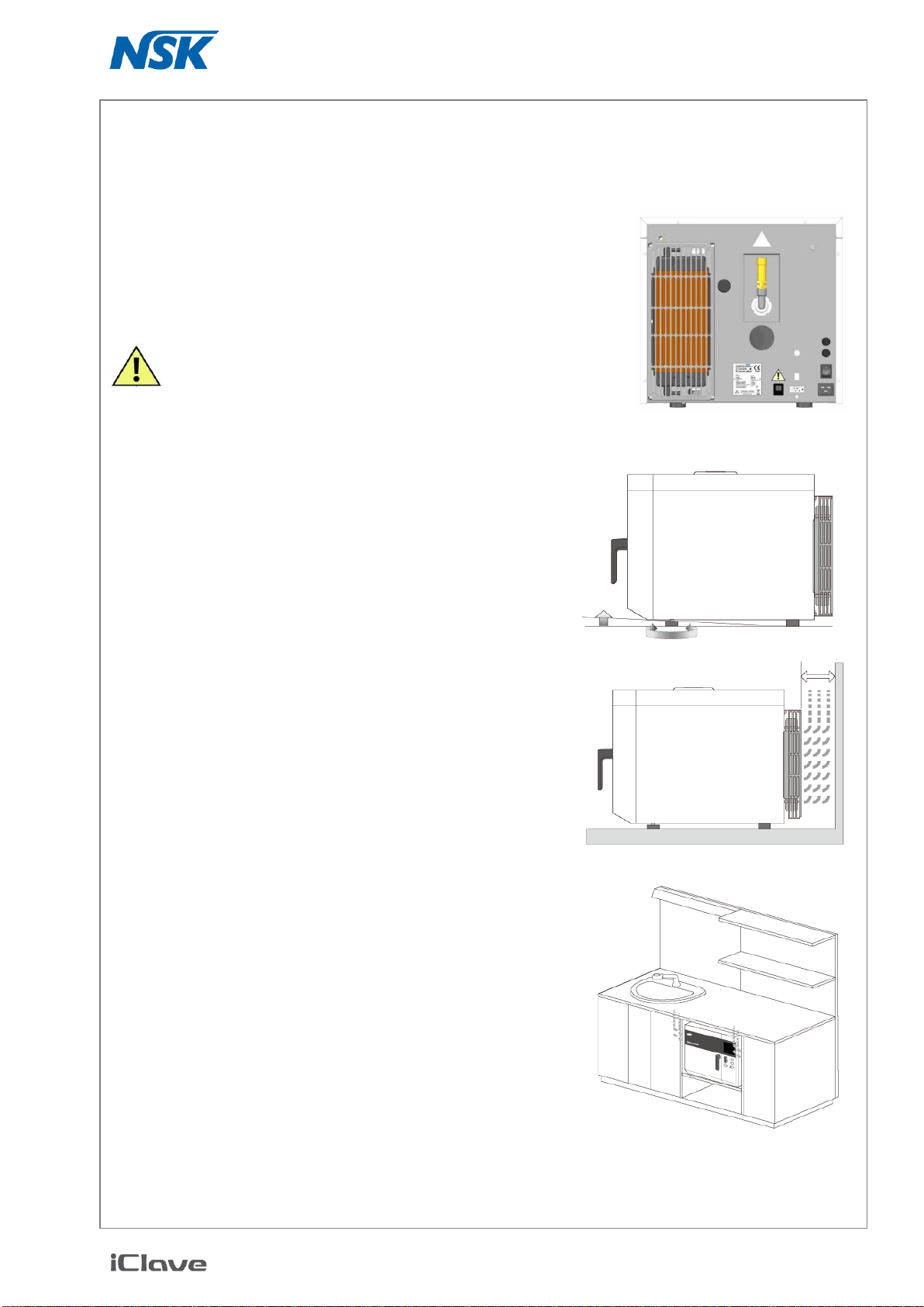
2. The equipment must be installed on a flat surface; adjust the
front feet to have a slight slope and so make the outflow of
water easier during the drain phase.
WARNING: do not place the unit on surfaces which
could cause fire or fume if hot items fall from the
equipment.
3. For the correct operation, it is mandatory to leave a free
space of at least 4 cm on the rear side of the equipment.
4. Do not install the equipment near heat sources, in humid or
not well aired environment; in a sterilization room is required
a minimum of 10 air changes per hour, a recirculating air
ventilation system (i.e. fan) can not be used in place of.
5. On the rear panel it is located the safety valve, if it operates
for overpressure, hot steam may be released: locate the
equipment in such a way to eliminate the risk of burning for
the operator (ex. near a wall).
If the sterilizer is installed in a cabinet, provide adequate space
(>10 cm) for aeration.
Missing cooling can cause failure or slow vacuum phases
4 cm
10
3.2 GETTING STARTED
These operations should be carried out only by qualified personnel, wrong settings could affect the
quality of the sterilization.
Check the electrical requirements and connect the power supply cable to the mains socket.
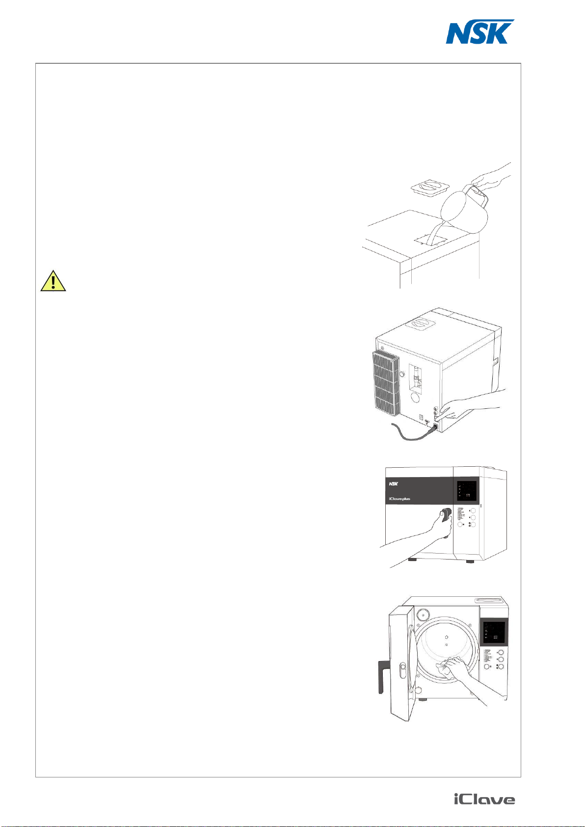
1. The equipment is delivered with empty tank and is therefore
necessary to add demineralized water. Be careful that the water
level does not exceed the white float (lever sensor) in the upper
part of the tank.
The use of low quality demineralized water could create
scale deposits on the instruments, inside the chamber and
on the trays. Carefully read the label of the demineralized
water container. Do not use tap water even if treated with
filters or sweeteners.
Do not use water for batteries, other liquids or
additives which can cause irreversible damage
to the equipment and be a risk for the operator.
2. Turn on the equipment with the main switch on the back panel.
This switch can be left ON since the electrical consumption in
stand-by is limited.
3. Remove the basket and the trays from the chamber and close
the door.
When the unit is off, the door is blocked; if the block per-
sists, turn off and then on again the unit.
4. Hold on the key UP and push the key Power; the display
shows the message <SET ALT 100 MT> with the set altitude
value (100 m).
Use the keys UP and DOWN to adjust the value as neces-
sary according to the actual site altitude (see next page).
Then push the key START to confirm the displayed value
and start the automatic initialization procedure with the entry of
water in the hydraulic circuit and chamber.
5. At the end of the initialization procedure the display shows
END INSTALL; open the door and dry the chamber with a
clean cloth.
In case of procedure steps not correctly followed, the display will
show one of the following warning messages:
DOOR OPEN: door not closed
ADD H2O: lack of water
NEED INSTALL: the initialization procedure not carried out
In this last case, repeat the procedure.
With procedure already been performed, pushing a button
the display will show OFF and the door stays blocked. To
unblock it, push the key Power.
The sterilizer is ready for use. Arrange basket and trays in the
chamber and select the sterilization cycle.
See Chapter 4«OPERATING INSTRUCTIONS».

11
3.3 NOTES ABOUT ALTITUDE COMPENSATION
For a proper operation of the pressure control devices, an altitude compensation feature has been intro-
duced.
During the installation procedure it is necessary to set the altitude value (referred to sea level) for the site
where the unit operates. This procedure must be carried out every time the unit is moved to a site with differ-
ent altitude from the one previously set.
During the factory test the equipment is set at a default value of 100m and can be left unchanged for real alti-
tude values between 0 and 200m, since a ±100m error does not affect the equipment operation.
To be sure of the sterilization process, it is important that the altitude tolerance from the current value does
not exceed 200m; otherwise, the vacuum devices should be additional loaded, and false or premature AL8 or
AL5 alarm should be signalled.
CONVERSION NOTE: to obtain meters multiply feet by 0.3048.
These operations should be carried out by qualified personnel. Wrong settings can affect the quality
of the sterilization.
12
4. OPERATING INSTRUCTIONS
4.1 FRONT PANEL COMMAND/SIGNALING
The front panel is equipped with control keys, signalling Led’s and displays. A slight push on a key
will activate the command.
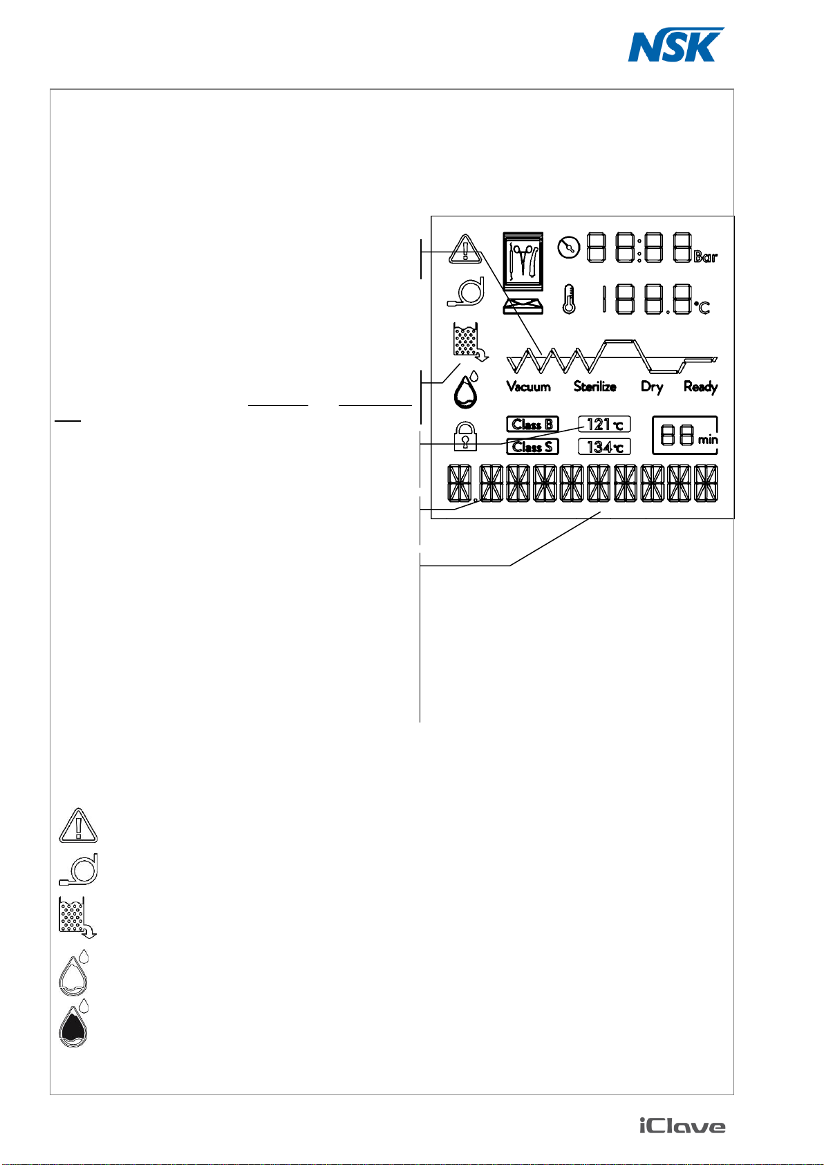
Symbols in the display:
When illuminated there is an alarm, the display shows "ALARM" followed by a number.
It lights up when you select the cycle T. TEST.
It lights up when the waste tank is full and require to be emptied.
Flashes when the fresh water tank is full of, stays on when there is enough water for the cycle.
Flashes when the fresh water tank is empty, It needs to be filled before you can make another cycle.
Phase in progress signalling
Led turned on or flashing during the phases of the cycle.
LCD displays
Visualize (from the top) the value of the parameters Time
(when the unit is OFF), Temperature (measure unit: °C)
and Pressure (measure unit: bar);
Current program signalling
Icons turned on for the selected temperature, time, S or B
type and kind of load
Reservoirs water level signalling
Turned on for water level in the main tank and waste water
tank at minimum or maximum value respectively.
Descriptive display
Displays information about the selected cycle, alarms, etc.
Backlight colour
The colour of the backlight depends on the phase and on
the condition:
RED alarm or manual stop
WHITE ready to operate
GREEN cycle completed
YELLOW cycle running
PURPLE setup and adjustment
13
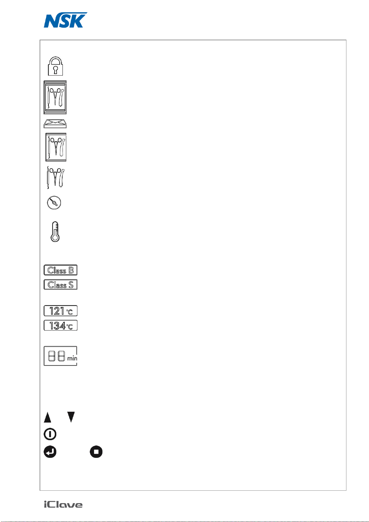
Door locked. When turned off, you can open the door.
Double wrapping, it lights up when you select the cycles 1, 2, 5, 6 or 7.
Packs, it lights up when you select the cycles 2 or 7.
Single wrapping, it lights up when you select the cycle 4.
Unwrapped instruments, it lights up when you select the cycle 3.
Pressure gauge. When it is on, the numbers to the right indicate the value of the pressure in the
chamber expressed in Bar.
Thermometer. When it is on, the numbers to the right indicate the value of the temperature in the
chamber expressed in Celsius degrees.
Cycle class indicators, B or S.
Temperature cycle indicators, 121°C for cycles 2 and 7; 134°C for cycles 1, 3, 4, 5 and 6.
Indicates the sterilization time depending on the selected cycle. Only during sterilization is acti-
vated the countdown to the remaining time at the end of this phase.
Keyboard:
UP, DOWN: select the program, the menu or the function.
POWER: turns on or off the unit, during the navigation in the menu it is used to exit/go back.
START / STOP: starts and stops the cycle, during the navigation in the menu is used to con-
firm the selection.

14
4.2 USB MEMORY CONNECTION
The USB plug is designed to release a cycle report for each cycle done.
This report is a .txt file saved on the USB memory stick connected on the plug located on the right side of the
display.
Insert or remove the stick ONLY when the unit is not running a cycle, there is a protection of the data
but there is a risk to lose some information.
The unit creates a file for each cycle, the name of the file is the same of the sequential number of the cycle,
on the file are written the main information for the traceability and the most important values of time, tempera-
ture and pressure.
The internal memory stores inside the unit the information of the previous 20 cycles (the maximum number
depends on the file dimension), so if the USB memory is missing of is defected it is possible to recovery
these data.
The USB stick must be selected in a high quality range for the safety of the data and it is needed to create a
fata backup.
The size of the data is limited to few Kbyte so a small capacity is needed, a big amount of data stored in the
USB stick decreases the speed of access, so it is suggested to delete the files from the memory stick when a
backup copy is done.
Every time that the USB stick is inserted in the unit, it compares the files contained with the files stored in the
internal memory, the missing files will be copied; it can take some seconds, in the meantime the function of
keyboard is locked - do not turn off the unit in this phase. The last 20 cycles stored in the unit are written
again in the memory, remember it when the backup is done.
If an external printer is used, the paper report may be the same of the USB or it may be a simplified report
with bar code in case of labels printer; in any case the USB file released is a complete report.
Because the file is not produced by a computer, in the file information is missing the creation date, this fea-
ture indicates that the file is really release by the unit and not manually created by PC
NSK is not responsible for data lost for missing care on the database or defective data support
15
4.3 RUNNING A STERILIZAZION CYCLE
1. Turn on the equipment by means of the switch located on the rear panel.
The display shows date, time and OFF; pushing UP, DOWN or START for short time) the brightness
of the display increases for few seconds
2. Push the key Power and wait for a few seconds the initial auto-test completion; during this time the pa-
rameter set-points and the type of the components currently tested will appear in a sequence on the dis-
play. Over the auto-test, the display will show the value of the current pressure and chamber temperature
(if lower than 35 °C the display will show the message “low”). The microprocessor enables the pre-heat-
ing step in order to rise the chamber temperature up to 100 °C.
The pre-heating phase is designed to keep warm the chamber so the cycles are faster, this function
increases the power consume in stand by condition; if the unit is not continuously used and the high
speed is not required, it is possible to set the unit in ECO MODE that keeps the chamber cold when
not needed. This system has not effect on the performance of the cycle. Look at SETUP pages.
During this phase the temperature reading on the display is inaccurate, because no steam being
there.
3. Arrange the material to be sterilized on the trays, load the chamber and close the door.
4. Check the indication of the water level, if missing fill up the main tank with demineralized water up to the
max level.
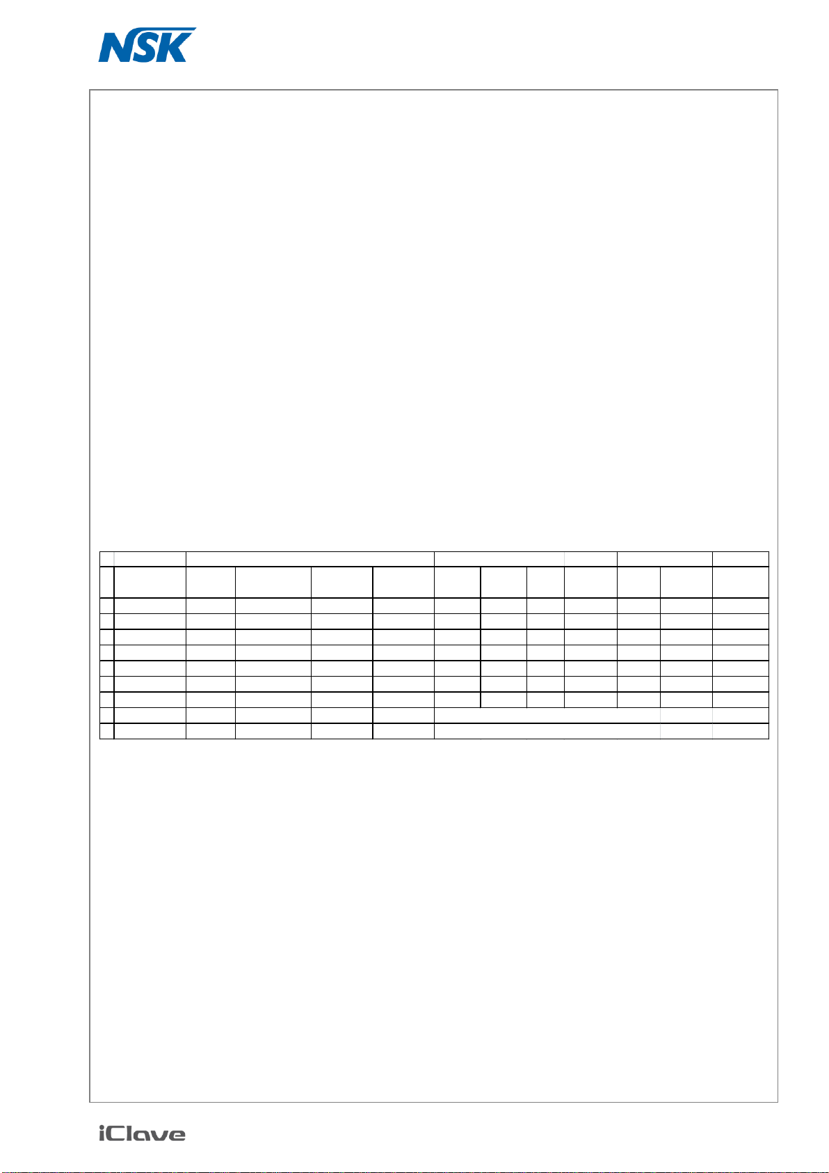
4.3.1 Available sterilization cycles
(*) In case of needs related to local regulations, the sterilization time of all the cycles may be increased on request by author-
ized technical service
(*) The cycle not needed may be eliminated from the selection on request by authorized technical service
(*) Liquids excluded
To select the programs push UP or DOWN.
The display will show the parameters selected and the type of admitted load
PROGRAM
LOAD TYPE
MAX LOAD
CYCLE TYPE
N.
NAME
VACUUM
PHASES
TEMPERATURE
(°C)
STERILIZ.
TIME (min.)
DRYING
TIME (min.)
HOLLOW
A
HOLLOW
B
SOLID
WRAPPED
SOLID
(Kg)
PROROUS
(Kg)
1
UNIVERSAL
3
134
5
10
Yes
Yes
Yes
Yes
4
1,5
B
2
DELICATE
3
121
20
12
Yes
Yes
Yes
Yes
4
1,5
B
3
FLASH
2
134
4
5
Yes
Yes
Yes
No
4
No
S
4
SMALL LOAD
3
134
4
5
Yes
Yes
Yes
Yes
0,5
No
B
5
PRION
3
134
18
10
Yes
Yes
Yes
Yes
4
1,5
B
6
CRITICAL 134°
4
134
5
14
Yes
Yes
Yes
Yes
4
1,5
B
7
CRITICAL 121°
4
121
20
16
Yes
Yes
Yes
Yes
4
1,5
B
8
SPECIAL
2, 3 OR 4
105 TO 135
3 TO 90
5 TO 14
DEPENDS ON THE VALUES SELECTED
T
TEST
3
134
3,5
10
ONLY FOR TESTING PROCEDURES
PARAMETERS

16
4.3.2 Starting a sterilization cycle
Press the key START/STOP to start the selected cycle.
The programs 3and 8do not warrant the Class B sterilization; to start these types of cycle, hold down
the key START longer than 3 seconds
It is possible to program a delated starting of the cycle: hold on the START button longer than 8 sec-
onds, the display will show HOUR DELAY, using UP and DOWN select the time delay in hours than
push START; the unit will turn off indicating the residual time before to start; the chamber will cool. It is
possible to delete this action turning on the unit with POWER
For unwrapped solid instruments we recommend to use the cycle 3In this way the sterilization time will be
faster, and power consumption reduced.
The door is locked and stays locked throughout the cycle duration.
The sterilizer starts and runs the cycle phases automatically. The various steps of the cycle are microproces-
sor controlled and sequentially shown on the display; in this way the operator can monitor the progress of the
sterilization phases and the times.
Vacuum phase (water entry in the chamber and pre-vacuum pulses)
During this phase the microprocessor enables the vacuum pump and enters a water dose in the
chamber. The icon Vacuum is flashing. This phase will be repeated more times and should require 10
to 20 minutes depending on the chamber conditions and load type to be processed. This phase may
be slightly noisy.
Sterilize
Reached the preset parameter values, icon Vacuum turns off and Led Sterilize turns on. The display
time starts the countdown marking the time remaining to the end of the sterilization phase.
The sterilization phase is followed by the decompression phase, the pressure decreases to 0. Again,
the display shows the countdown of the decompression phase. Based on our experiences, the decom-
pression time has been slightly extended in order to minimize the thermal shock consequent to the sta-
tus change of the steam.
Drying
Over the decompression phase, Sterilize icon starts to flash to signal the completion of the steriliza-
tion process. At the same time Dry turns on, signalling the start of the drying phase. Throughout this
phase, the chamber heaters keep the chamber warm according to a microprocessor-controlled logic,
the vacuum pump comes again into operation to eliminate the residual moisture. The display shows
the countdown of this phase. Follows the forced ventilation phase through the bacterial filter –the dis-
play shows also the countdown of this phase.
End of the cycle
As soon as the drying is over, Dry turns off and Ready and Sterilize turn on. A 10-second alert signal
is generated to draw the attention by the operator. The chamber heaters are set at reduced power
(pre-heating, only if ECO MODE is not selected) until the door is open. The TIME display shows the to-
tal time of the cycle, the displays TEMP. and PRESS show respectively the current temperature and
pressure of the chamber.
At the end of cycle 3 or 8 only the Led READY will light and not STERILIZE to signal that
the cycle selected by the operator does not warrant a Class B sterilization;the display will
show the cycle counter.

17
To unlock the door before opening it, press the key Start/Stop.
The cycle is over and the load can be taken out .
ATTENTION: instrument and chambers are hot
If a label printer is used, at the end of the cycle the display will ask to select the number of labels need-
ed, select the value with UP and DOWN, than opening the door the printer will release the labels.
Opening the door, the displays will show again the current time, chamber temperature and pressure,
and the sterilizer is ready for a new cycle.
If an external serial printer is connected, a report will be issued during the cycle phases with the more
significant data; the report can be filed as proof of the sterilization process performed.
The operator can arrange other load on the trays and start a new sterilization cycle. with the advantage
of shorter heating-up time as the chamber is already warm, or press key Power to put the unit in
stand-by status (OFF on the display).
If the door is not opened or a key pressed within 30 minutes, the unit switches to stand-by
(OFF) automatically.
WARNING:
Should any failure or error occur during the cycle, Led Alarm turns on, the display Time will show the
type of alarm (see chapter ALARM) and the door remains locked. To unlock the door, press key
Start/Stop.
ATTENTION: instrument and chambers are very hot.
Contamination risk.
4.4 STOPPING THE CYCLE
To stop the sterilization cycle, press key Start/Stop.
The display Time shows the message “MANUAL STOP”.
Before opening the door, make sure that the display Pressure is showing the value 0. A safety device locks
the handle when the chamber under pressure. To unlock the door press key Start/Stop.
Remove the load and check for the presence of water into the chamber. In case of wrapped instruments, we
suggest to replace with new bags.
Before loading the chamber again, dry it carefully and wait 10 minutes to allow the water to evaporate and be
drained completely.
18
4.5 TOPPING UP AND DRAINING THE WASTE WATER TANK
The sterilizer is fitted with two 4-liters tanks; main tank for the fresh demineralized water and recovery tank for
the waste water .
The hydraulic system does not reuse the condensate obtained during the sterilization process; this conden-
sate is collected in the waste water tank which must be periodically drained (except when used in combina-
tion with the water supply system Purity). This mode of operation involves the progressive emptying of the
main tank and the filling of the waste water tank.
4.5.1 Topping up the main tank
The average water consumption per sterilization cycle is 520 cc, hence 6 cycles can be performed with a full
tank (depends of the cycle selection)
The icon of the fresh water reservoir (main tank) blinks when it is full, when the maximum level is reached,
seven acoustic signals are released when the maximum is reached the first time (it will happen again only af-
ter one cycle or if the unit is switched off), then the icon will blink again with the empty symbol when there is
not enough water to run another cycle (the current cycle will be anyway completed).
Provide the topping up of the main tank, taking care not to exceed the maximum reference level marked by
the white float (level sensor) in the upper part of the tank. The blinking of the full drop icon and an acoustic
warning signals that the tank is full.
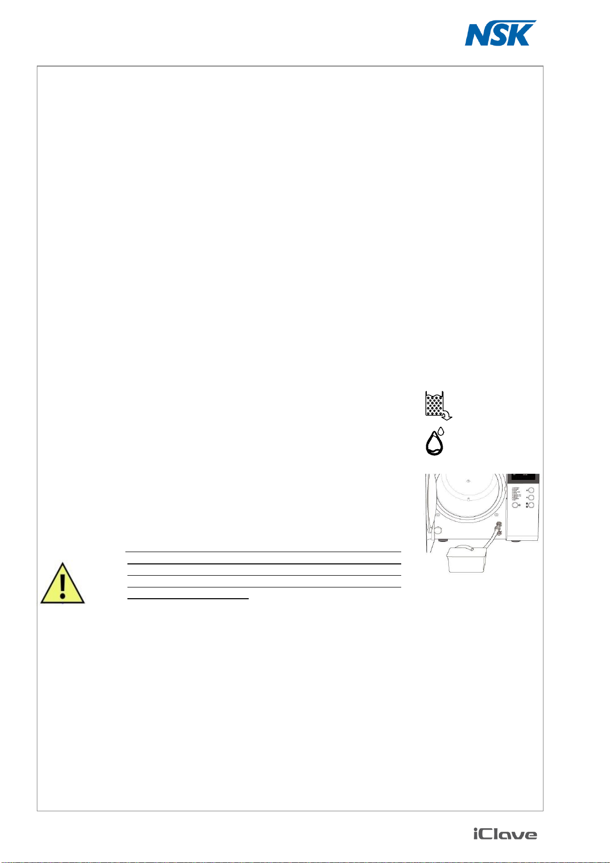
4.5.2 Draining the waste water tank
The lighting of the waste water reservoir icon rela-
tive to the waste water tank warns that the maxi-
mum level has been reached. In this case :
Get a bucket or a tank of at least 4 l capacity,
Fix the supply drain tube into the upper fast fitting (black),
Wait for a complete draining,
Unfit the tube pushing the button on the connector and drawing the tube.
CAUTION! The water contained in the waste water tank is to be regard-
ed as biologically contaminating, therefore when this tank is
emptied, suitable precautions should be taken. The disposal
of recovery water needs to be done in accordance with the
national or local regulation.
Table of contents


