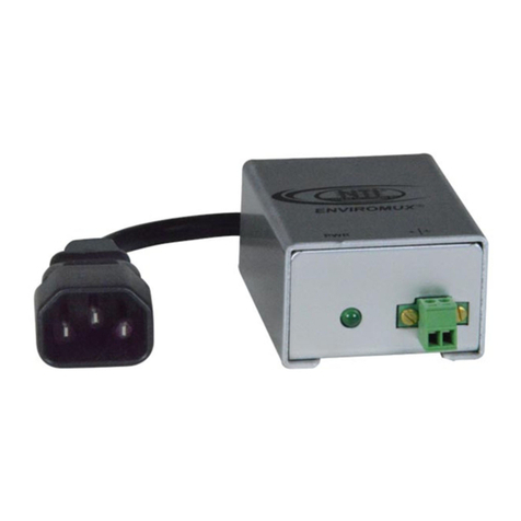
NTI ENVIROMUX-FENCE1 User manual


3
MounttheVIB200directlytothefabricofthechainlinkorwiremesh,on
theinteriorsideoftheprotectedareaasshownintheillustrated
examples,ataheightof4‐5feetand1footfromapost.
Themountinghardware
consistsofanaluminum
platewithtwoscrews,
usedtoclampthesensor
enclosuretothefence
fabric.
Looselysecurethe
mountingbrackettothe
VIB200,withonescrew
onlyintheuppercorner
of the VIB200
Feedthebracketthru
thefencefabric
diagonally,downandto
theright,capturing2‐3
wires,dependingonlink
size.
4
Securetheothercorner
oftheVIB200tothe
bracketusingthe
remainingscrew,
centeringtheVIB200in
thelinksandtightenso
thattheVIB200makes
goodcontactwiththe
chainlinks.DONOT
OVERTIGHTEN.
Thereisnoneedto
tightensomuchthatthe
bracketispulledfullyto
thecaseandbentor
thatthecaseofthe
VIB200casebeginsto
twistanddeform.This
willpreventawater
tightsealwiththelid.

5
KEYCOMPONENTS:
A BC
ProgrammingPort:FactoryOnly
**DoNotRemoveCover**
RedLED:AlarmOutput
AmberLED:QualifiedEvent
GreenLED:ActivityontheFence
JP1
JP1A:On=LEDEnable,Off=LED
Disable
JP1BANDC:SensitivitySettings
Terminal:4Positions:‐12V
Common,AlarmOutput,+12V
PowerandPowerFailureOutput
6
LEDs:
EachVIB200hasthreeLEDs–Green,AmberandRed.TheseLEDsindicate
theresponseofthesensortoimpactsorcutstothefence.
GreenLED‐TheGreenLEDwillindicatethattheVIB200hasreceiveda
signalfromtheimpactandwillprocessthatsignaltoqualifyitasavalid
event.IftheGreenLEDdoesnotflashduringavalidattackuponthe
fence,thesensitivityoftheVIB200mustbeincreased,orthedistance
betweenthesensorsreduced.Also,ifthereisasteadywindorthe
fenceisvibratingasifthereisasteadywindthentheGreenLEDwillnot
illuminateunlesstheimpactexceedsthevibrationduetowind.Note:
DisconnectpoweraftereachtesttoresetLEDfunction,seebelow
TESTING.
YellowLED–TheYellowLEDwillindicatethattheVIB200hasqualifieda
signalasavalidevent.IftheGreenLEDflashes,buttheYellowdoesnot
flashduringavalidattackuponthefence,thesensitivityoftheVIB200
mustbeincreased,orthedistancebetweenthesensorsreduced.
RedLED–TheRedLEDwillindicatethattheVIB200hascounted
enougheventstoqualifyasanalarmandhasproducedanalarmoutput.
SELECTINGTHESENSORSENSITIVITYFORYOURFENCE:
EachVIB200Sensorhasfoursensitivitysettings‐HighSensitivitywith
WindMode,LowSensitivitywithWindMode,HighSensitivityandLow
Sensitivity.Abuiltinmicroprocessorcountsandtimesthepulses
generatedbyanimpacttothefence.Thedifferentsensitivitiesallowyou
toselectanalarmoutputspecifictoyourfencethatmatchesupwiththe
quantityofpulsesanddurationofpulsesofavalidattack.
Inordertoselectthedesiredsensitivityforyourfence,therearetwo
removableJumpers,JP1‐BandJP1‐C.TheJumpersallowyoutoselect
fromthefourpre‐programmedalarmsensitivities.

7
JP1‐BOn,JP1‐COn=HighSensitivitywithWindMode
JP1‐BOn,JP1‐COff=LowSensitivitywithWindMode
JP1‐BOff,JP1‐COn=HighSensitivity
JP1‐BOff,JP1‐COff=LowSensitivity
RemovepowertotheVIB200SensorpriortochangingJumpers.Once
Jumpersareputbackinthedesiredpositionreconnectpower.
Choosingthesensorsensitivitydependsuponthequalityofthefence‐
looseortight,heavyorlightlinkgauge,oldornew,theheightofthe
fence‐short5ft.toregular6‐8ft.totall>8ft.andthesurrounding
environment‐remoteorpublic,protectedorwindy.Selectingthe
sensitivityisabalancebetweengeneratinganalarmoutputuponavalid
attacktothefenceandfilteringoutnuisanceevents.Onanewtightfence
ofregularheight,thesensorwillworkwellwithalowsensitivitysetting.
Onalooseorolderfence,theVIB200willworkbestwithahighsensitivity
setting.Highsensitivitysettingscanbeselectedforremoteareaswithno
publicaccessbutlowsensitivitysettingsarebetterforfencesadjacentto
publicareas.
Inadditiontotworegularsensitivitysettings,HighandLow,theVIB200
hastwosensitivitysettingswith“WindMode”.InWindModetheVIB200
measuresvibrationonthefenceduetowindoraconstantvibration
sourceandmeasuresanimpactduetoclimbingorcuttingagainstthis
constantvibration.InWindModethesensitivityoftheVIB200sensorwill
decreasewithanincreaseinwind.Forthisreasonthetwosensitivity
settingswithWindModearelesssensitivethanthetwosettingswithout
WindMode.Ifthefencethatisbeingprotectedisinaclearareawith
windthenselectoneofthesensitivitysettingswithWindMode.Ifthe
fenceisinanareawithlittlewindorprotectedbyotherbuildingsthen
chooseoneoftheregularsettings.
8
TESTING:
WiththeVIB200mountedtothefenceandthecoverremoved,selectthe
sensitivitywithJumpersJP1‐BandJP1‐Cpertheguidelinesabove.Hook
upa9Vbatterytothesensor.Testtheabilityofthesensortodetect
impactsandclimbsatthedesiredrange(30to50feet).Movethesensor
tovariouspartsofthefenceandtest.TheLEDswillalertyoutothe
responseofthesensor.OneoftheuniqueaspectsoftheFlairVIB200is
thateachindividualsensorcanbetunedtoaparticularfencesection.
Oftenthequalityofthefencecanvaryfromonesectiontothenext.
DecreaseorincreasethesensitivityofthesensorbychangingJumpers
JP1‐BandJP1‐Ctogenerateanalarmuponthedegreeofimpact/attack
tothefenceyouwanttoidentify.Agoodruleofthumbistoselecta
sensitivitythatgeneratesanalarmatthe3rdor4thstepinaclimb.Atthis
sensitivitythesensorshouldnotgenerateanalarmatasingleimpactto
thefence.
Whentestingwithabattery,youmustdisconnectthebatteryfromthe
sensoraftereachtestinorderforthesensorcounterandtimertoreset.
Thecounterswillalsoresetoncethesensorproducesanalarmoutput
andtheREDLEDflashes.Don’tforgettodisconnectthebatterywhen
changingthesensitivitysettingalso.
Onceyouhaveselectedanappropriatesensitivityandsensorspacing,
mountallofthesensorstothefenceandwiretopowerandalarm
control.Atanytime,thesensitivityofoneormoreoftheVIB200sensors
maybechangedtotunethemtoaparticularsectionoffenceordesired
response.

9
WIRING:
TheAlarmisanopencollectoroutput‐normallyopen.ThePower
Troubleisanopencollectoroutput–normallyclosed.TheAlarmOutput
willprovideanelectricalshorttogroundwhenactivated.ThePower
TroubleOutputwillopenwhenactivated.RefertoyourAlarmControl
Panel’sInstructionManualforinstructionsonhowtowireopen
collectoroutputstothezoneinputsofthepanel.
Diagram1:OutputElectricalConfiguration
Wrapwirearound
terminalforbest
connection.
JumpersJP1‐Aisused
toturnOn/OffLEDs.
JP1‐BandJP1‐Care
usedtoselect
sensitivity.
Keepwhitefivepin
coveronserialportto
protectpins.
10
WIRING(Continued):
TheVIB200maybewiredwithoneloopforalarmandoneloopforpower
troubletobemonitoredbytwozonesoncontrolpanelorthealarmand
powertroublemaybecombinedononeloop.
AlwaysconnecttheEnd‐of‐LineResistorsinthelastVIB200alongthe
zonerun.Note:OnlongrunsyoumayneedtoadjustthevalueoftheEOL
Resistortocompensateforanyvoltagedropalongtheloop.CallFlairto
workoutbestresistorvalue.
Diagram2:WiringDiagramforcombinedalarmandpowertroubleloop

This manual suits for next models
1
Table of contents
Other NTI Security Sensor manuals