NTI KEEMUX-P2-LC Operation manual

KEEMUX-P2-LC (2-Port PS/2 KVM Switch)
INSTALLATION / USER GUIDE
MAN019 Rev Date 7/18/2001
NTINTI NETWORK
TECHNOLOGIES
INCORPORATED
Tel:330-562-7070
Fax:330-562-1999
1275 Danner Dr
Aurora, OH 44202
VGA
Multi-Scan
Monitor
PS/2
PS/2 Keyboard
PS/2 Mouse
PS/2
NTINTI
NETWORK
TECHNOLOGIES
INCORPORATED
KEEMUX-P2-LCKEEMUX-P2-LC
CPU
SELECT
1 2
USER
CPU2
CPU1
330-562-7070
www.nti1.com

1
TABLE OF CONTENTS
INTRODUCTION.....................................................................................................................................................................1
MATERIALS.............................................................................................................................................................................1
INSTALLATION.......................................................................................................................................................................2
USING THE NTI SWITCH ......................................................................................................................................................3
CPU SELECT BUTTON.....................................................................................................................................................................3
KEYBOARD CONTROL.....................................................................................................................................................................3
COMMAND MODE..............................................................................................................................................................................3
SCAN MODE........................................................................................................................................................................................4
NORMAL MODE..................................................................................................................................................................................4
RESET SWITCH.....................................................................................................................................................................4
KEYBOARD FEATURES........................................................................................................................................................4
TECHNICAL SPECIFICATIONS............................................................................................................................................5
TROUBLESHOOTING............................................................................................................................................................5
WARRANTY INFORMATION.................................................................................................................................................6
COPYRIGHT...........................................................................................................................................................................6
INTRODUCTION
The KEEMUX-P2 LC KVM switch allows one user to access two PS/2 computers with only one keyboard, monitor, and mouse.
Internal microprocessor driven circuitry allows both computers to boot simultaneously and error-free.
MATERIALS
Materials Supplied with this kit:
NTI KEEMUX-P2-LC KVM Switch
Materials Not Supplied, BUT REQUIRED:
A set of 2 cables for each PS/2 computer being connected to the switch must be used:
1. VEXT-xx-MM for monitor interface
2. (1) VVKINT-xx-MM for keyboard and mouse interface.
OR
VKMEXT-xx-MM for keyboard, mouse, and monitor interface
Legend: xx is the length of the cable in feet.
MM indicates male-to-male connector.
Cables can be purchased from Network Technologies Inc.

2
INSTALLATION
1. Turn OFF power to both computers that will be connected to the KEEMUX-P2-LC switch before connecting or disconnecting
any cables
WARNING! DAMAGE MAY OCCUR TO THE COMPUTER IF POWER IS NOT DISCONNECTED BEFORE CONNECTING OR
DISCONNECTING CABLES.
2. Connect a PS/2 keyboard to the "USER" purple female 6 pin miniDIN keyboard port on the side of the KEEMUX-P2-LC
switch.
3. Connect a PS/2 Mouse to the “USER" green female 6 pin miniDIN mouse port on the side of the KEEMUX-P2-LC switch.
4. Connect a VGA multi-scan monitor to the"USER" female 15HD monitor port on the side of switch. Be sure to tighten the two
screws on the monitor cable connector to the KEEMUX-P2-LC switch securely.
5. Using a VVKINT-xx-MM or the 6pin miniDIN cable ends of a VKMEXT-xx-MM, connect keyboard and mouse ports of a PS/2
computer to the CPU1 purple female 6 pin miniDIN keyboard and green female 6 pin miniDIN mouse ports on the side of the
KEEMUX-P2-LC switch.
6. Using a VEXT-xx-MM or the 15HD cable ends of a VKMEXT-xx-MM, connect the video port of a PS/2 computer to the CPU 1
female 15HD monitor port on the side of the KEEMUX-P2-LC switch. Be sure to tighten the two screws on the cable
connector to the KEEMUX-P2-LC switch securely.
7. Repeat steps 5 & 6 for connecting a second PS/2 computer to the CPU 2 video, keyboard, and mouse ports on the opposite
side of the KEEMUX-P2-LC switch. See Fig. 1.
Fig. 1
Symbols Legend
Monitor Keyboard Mouse
VGA
Multi-Scan
Monitor
PS/2 Keyboard
VEXT-xx-MM VVKINT-xx-MM
PS/2
PS/2 Mouse
NTINTI
NETWORK
TECHNOLOGIES
INCORPORATED
KEEMUX-P2-LCKEEMUX-P2-LC
CPU
SELECT
1 2
USER
CPU2
CPU1
330-562-7070
www.nti1.com
Screws to hold
connector
on tight
Purple
Green
Purple Green

3
POWER-UP SEQUENCEPOWER-DOWN SEQUENCE
1. The KEEMUX-P2-LC is powered by the computers it is connected to. 1. Power-down computers.
2. Turn ON power to monitor. 2. Power-down monitor.
3. Turn ON power to either or both computer(s).
USING THE NTI SWITCH
The NTI KEEMUX-P2-LC KVM switch can be operated by the CPU SELECT button on the side of the switch or by keyboard
control.
CPU SELECT BUTTON
1. Pressing the CPU SELECT button on the side of the KEEMUX-P2-LC switch will toggle between CPU 1 and CPU 2 which
connects the selected computer to the user's keyboard, monitor, and mouse.
2. Holding down the CPU SELECT button for more than 2 seconds will cause the switch to cycle through all modes of
operation: COMMAND, SCAN, and NORMAL (see below for Command, Scan, and Normal Mode sections). Release the
button when the desired mode has been selected.
KEYBOARD CONTROL
1. To toggle between ports 1 and 2: Press
With each use of this sequence CPU LEDs 1 and 2 will alternately cycle ON and OFF, with the illuminated LED indicating which
port is active after the sequence.
NOTE: This sequence will not work from within Command Mode.
2. In order to control the other features of the switch with the keyboard, Command Mode must be enabled. To enter/exit
Command Mode from the keyboard:
Press
When the Command Mode is ON, all 3 status lights on the keyboard will illuminate and both LEDs on the KEEMUX-P2-LC will go
OFF to indicate Command Mode is enabled and the following functions are available: (NOTE: The user must exit Command
Mode in order to type to a computer.) Mouse movement will be frozen while in Command Mode.
COMMAND MODE
Function: Keystroke:
Toggle Scan Mode
ON and OFF
Sets scan time-out
period for each port.
Exit Command Mode
`
+
Ctrl ~(ACCENT
KEY)
`
CHORDED SEQUENCE- PRESS CONSECUTIVELY
AND KEEP KEYS PRESSED UNTIL ALL ARE PRESSED.
+
-PRESS CONSECUTIVELY
KEY SYMBOLS LEGEND:
T--(xxx from 002 to 255. ie. t002 would set the time-out
period for 2 seconds. Note: all three digits must be
used including the leading zeros, ie. 2 seconds= "002".)
-
(0-2)
x (0-9)
x (0-9)
x
S(When toggled to ON, Scan Mode is indicated by both CPU LEDs on
the KEEMUX-P2-LC alternately cycling ON and OFF, until the user
exits Command Mode, at which time the LED for only the active CPU
will flash ON and OFF as described below.)
Esc `
+
Ctrl ~(ACCENT
KEY)
`
OR
Ctrl Ctrl
-
4
A flashing CPU LED
means
that CPU is being scanned
and is active.
CPU
SELECT
1 2
View of side of switch with LEDs
and CPU SELECT switch
SCAN MODE
Scan Mode is indicated by a flashing CPU port LED. In Scan Mode the switch scans back and forth between ports
making the CPU connected to the port with the flashing LED active. That port will remain active while in use until
the port becomes idle for the user selected time out period (default time is 5 seconds) before switching to the other
CPU port. See Command Mode section on page 3 for configuring the scan time out period.
NOTE: The keyboard and mouse must remain idle for the full scan time out period before the KEEMUX-P2-LC switch
selects the other port.
NORMAL MODE
The KEEMUX-P2-LC is in Normal Mode when only the LED for the active CPU is illuminated solid (not flashing as in Scan Mode).
When in Normal Mode, the user is controlling only the computer to which the user is connected through the KEEMUX-P2-LC
switch. In Normal Mode the KEEMUX-P2-LC will only switch between CPUs 1 and 2 when the user uses either keyboard control
or button control to do so.
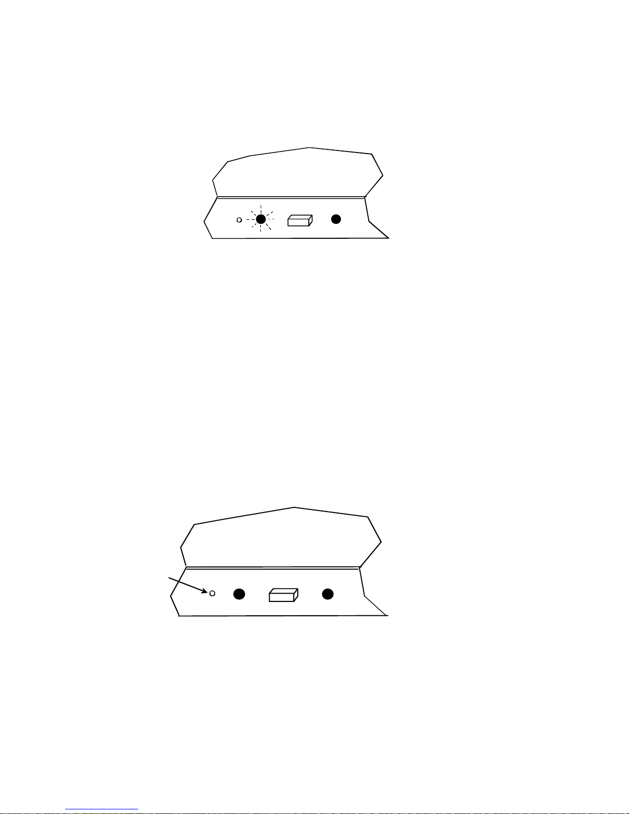
RESET SWITCH
A reset switch is located inside a small opening in the KEEMUX-P2-LC switch housing just to the left of the CPU 1 LED (see Fig.
3). This switch is provided to enable a user to reset the KEEMUX-P2-LC switch in the event the keyboard, mouse, or monitor
stops working properly. The KEEMUX-P2-LC switch can be reset by inserting any object small enough to fit in the opening
(paperclip, pencil tip, etc.) and requires only momentary pressure to reset. Follow the steps outlined under the
TROUBLESHOOTING section on page 5 before using the reset switch.
KEYBOARD FEATURES
The keyboard configuration of each computer is saved in the NTI KEEMUX-P2-LC KVM switch. For example, if the computer
attached to Port 2 had CAPS LOCK and NUM LOCK selected the last time that computer was accessed, then they will
automatically be set when that computer is accessed again.
Fig. 2
Fig. 3
CPU
SELECT
1 2
View of side of switch with LEDs
and CPU SELECT switch
Reset
Switch

5
TECHNICAL SPECIFICATIONS
PS2 Keyboard or Mouse VGA Video
Pin # Signal PIN# Signal Pin # Signal
1KYBD DATA 1RED 9NC
2MOUSE DATA 2GREEN 10 GND
3GND3BLUE 11 ID0
4+5 4ID2 12 ID1
5KYBD CLOCK 5TST 13 HS
6MOUSE CLOCK 6RED GND 14 VS
7GREEN GND 15 NC ID3
8BLUE GND
TROUBLESHOOTING
1. Verify all cables are securely connected and that the installation procedure was carefully followed.
2. Verify that the power-up sequence was observed.
3. If a computer seems to be locked up, press the CPU SELECT button a couple of times.
4. If a computer is still locked up, unplug the USER keyboard and mouse cables (not the CPU keyboard and mouse) from the
KEEMUX-P2-LC switch and reconnect them.
5. If the problem still exists, press the reset switch (see Fig. 4) momentarily with any small object able to fit in the opening in the
case (pencil, paperclip, etc.).
If the NTI KEEMUX-P2-LC KVM switch still seems to not work properly, help may be found in the Frequently Ask Questions
(FAQ’s) section of our website at http://www.nti1.com or call us directly at (800) 742-8324 (800-RGB-TECH) or (330) 562-7070
and we will be happy to assist in any way we can.
Fig. 4
Mating face of a 6 pin miniDIN female
PS/2 KEYBOARD OR MOUSE
21
4 3
65
Mating face of a 15HD female
VGA VIDEO
42
3
5 1
10 9 8 6
7
15 14 13 12 11
CPU
SELECT
1 2
View of side of switch with LEDs
and CPU SELECT switch
Reset
Switch

6
WARRANTY INFORMATION
The warranty period on this product (parts and labor) is one (1) year from the date of purchase. Please contact Network
Technologies Inc at (800) 742-8324 (800-RGB-TECH) in the US and Canada or (330) 562-7070 (worldwide) for information
regarding repairs and/or returns. A return authorization number is required for all repairs/returns.
COPYRIGHT
Copyright © 2001 by Network Technologies Inc. All rights reserved. No part of this publication may be reproduced, stored in a
retrieval system, or transmitted, in any form or by any means, electronic, mechanical, photocopying, recording, or otherwise,
without the prior written consent of Network Technologies Inc, 1275 Danner Drive, Aurora, OH 44202
CHANGES
The material in this guide is for information only and is subject to change without notice. Network Technologies Inc reserves the
right to make changes in the product design without reservation and without notification to its users.
SERIAL NO.:
DATE:
INSPECTED BY:
oKEEMUX-P2-LC
Table of contents
Other NTI Switch manuals

NTI
NTI ST-nXm-USBV-U Operation manual

NTI
NTI UNIMUX-HD4K-x User manual

NTI
NTI SE-DVI-2A User manual

NTI
NTI ST-xU User manual

NTI
NTI PRIMUX-RDSW User manual

NTI
NTI SM-4X4-4K18GB-LC User manual

NTI
NTI VOPEX-3V-SE-2 Operation manual

NTI
NTI UNIMUX-nXm-UHD User manual

NTI
NTI ST-nXm-U-HD User manual

NTI
NTI UNIMUX-2X8-U User manual

NTI
NTI UNIMUX Series User manual

NTI
NTI RACKMUX-V15-4UNV User manual

NTI
NTI SERIMUX-S-x User manual

NTI
NTI KEEMUX-Sx-O User manual

NTI
NTI 1394-HUB-5-x FW106 Operation manual

NTI
NTI USBV-x User manual
-xhd User manual")
NTI
NTI unimux-dvi(a)-xhd User manual

NTI
NTI SERIMUX-SECURE-x User manual

NTI
NTI RACKMUX-V15-N-PRIMUX User manual

NTI
NTI SPLITMUX Series User manual


