NTI UNIMUX-HD4K-x User manual

MAN305 Rev Date 6/1/2018
UNIMUX-HD4K-x
4K Video USB KVM Switch
Installation and Operation Manual
UNIMUX-HD4K-32 (Front and Rear View)
UNIMUX Series

i
TRADEMARK
UNIMUX is a trademark of Network Technologies Inc in the U.S. and other countries
COPYRIGHT
Copyright © 2000, 2018 by Network Technologies Inc. All rights reserved. No part of this publication may be reproduced, stored
in a retrieval system, or transmitted, in any form or by any means, electronic, mechanical, photocopying, recording, or otherwise,
without the prior written consent of Network Technologies Inc, 1275 Danner Drive, Aurora, Ohio 44202.
CHANGES
The material in this guide is for information only and is subject to change without notice. Network Technologies Inc reserves the
right to make changes in the product design without reservation and without notification to its users.
.
Typographic Conventions
The table below offers examples of text format and its meaning when that format is used in place of the standard font (Helvetica)
used throughout this manual.
Typeface meaning Font Configuration Example
On-screen computer output Courier New-(not bold) C:>
What you type on the computer Courier New-bold C:>edit text.bat

ii
TABLE OF CONTENTS
INTRODUCTION.............................................................................................................................................................1
Features....................................................................................................................................................................1
MATERIALS....................................................................................................................................................................1
FEATURES AND FUNCTIONS.......................................................................................................................................2
RACKMOUNTING INSTRUCTIONS...............................................................................................................................3
To Mount to a Rack .....................................................................................................................................................3
INSTALLATION...............................................................................................................................................................4
RS232 Connection.......................................................................................................................................................6
Power-Up Sequence....................................................................................................................................................7
Limitations....................................................................................................................................................................7
USING THE UNIMUX SWITCH ......................................................................................................................................8
Front Panel Control......................................................................................................................................................8
Keyboard Control.........................................................................................................................................................8
USER ACCESS FUNCTIONS.........................................................................................................................................9
Command Mode..........................................................................................................................................................9
Navigation.................................................................................................................................................................9
Settings Menu.........................................................................................................................................................10
Broadcast Mode......................................................................................................................................................11
Scan Mode..............................................................................................................................................................12
Normal Mode ..........................................................................................................................................................13
Administrator Settings.............................................................................................................................................14
Port Name List........................................................................................................................................................15
RS232 CONTROL.........................................................................................................................................................16
RS232 Connections and Configuration.....................................................................................................................16
Remote Connection................................................................................................................................................16
Baud Rate...............................................................................................................................................................16
Command Protocol.................................................................................................................................................16
NTI Switch Control Program For Windows 9X, NT, 2000, XP, Vista,7, 8 and 10 ....................................................17
SerTest- RS232 Interface Test Program...................................................................................................................18
Main Options...........................................................................................................................................................18
KEYBOARD FEATURES..............................................................................................................................................22
Keyboard-To-Computer Translation..........................................................................................................................22
Translation Capabilities ..........................................................................................................................................22
TROUBLESHOOTING..................................................................................................................................................23
INDEX............................................................................................................................................................................23
WARRANTY INFORMATION........................................................................................................................................23
TABLE OF FIGURES
Figure 1- Secure rackmount ears to switch.....................................................................................................................3
Figure 2- Secure switch to a rack....................................................................................................................................3
Figure 3- Connect a VGA multi-scan monitor .................................................................................................................4
Figure 4- Connect the device(s)......................................................................................................................................4
Figure 5- Connect the AC line cord.................................................................................................................................5
Figure 6- Connect each CPU..........................................................................................................................................5
Figure 7- Connect Terminal for RS232 Control...............................................................................................................6
Figure 8- Compatible device combinations.....................................................................................................................7
Figure 9- Port List (Main Menu) ......................................................................................................................................9
Figure 10- Help Menu....................................................................................................................................................10
Figure 11- Settings Menu..............................................................................................................................................10
Figure 12- Stop USB Device Reminder warning...........................................................................................................11
Figure 13- Settings Menu..............................................................................................................................................11
Figure 14- Broadcast List..............................................................................................................................................12
Figure 15- Settings Menu..............................................................................................................................................12

iii
Figure 16- Scan List......................................................................................................................................................13
Figure 17- Administrator Settings..................................................................................................................................14
Figure 18- Port Name List.............................................................................................................................................15
Figure 19- RS232 Communication Illustrated...............................................................................................................16
Figure 20- Keyboard Layouts........................................................................................................................................22

NTI UNIMUX SERIES 4K VIDEO USB KVM SWITCH
1
INTRODUCTION
The UNIMUX-HD4K-x 4K Video USB KVM switches allow a single user to control of 4, 8, 16, 24, or 32 computers with an HDMI
monitor and USB keyboard and mouse. These switches feature an on-screen display (OSD) and a fully transparent USB switch.
(This means that when a USB device is connected to a transparent USB port, it is the same as if the device was being plugged
directly into the computer's USB port.) Connections use standard HDMI and USB cables.
HDMI 1.4 resolutions up to 4k @ 30Hz are supported.
The transparent switch is capable of supporting any two low-, full-, or high-speed USB 2.0 devices, including but not limited to
touchscreens, card readers, printers, scanners, and thumb drives.
Note: Devices vulnerable to data corruption upon surprise removal, such as thumb drives, have to be stopped by the user before
switching hosts (i.e., by Windows safely remove hardware or Mac eject device). A warning to this effect, requiring user
confirmation, is displayed on the OSD when attempting to switch hosts or enter scan mode. This warning appears by default,
though it is possible to disable it in the switch settings.
Internal microprocessor circuitry allows all USB CPUs to be booted simultaneously without keyboard error. Port selection is
accomplished by front panel push buttons or commands typed on the keyboard. Port lights and status LEDs continuously update
on the front panel. Video formats up to 2560x1440 can be displayed from all platforms.
Features
HDMI 1.4, DVI compatible (with optional HDMI to DVI cable).
Resolutions to 2560x1440 (computer), 3840x2160 (UHD), and 4096x2160 (4K) @ 30Hz / 4:4:4 RGB (resolutions limited
to 1920x1200 when mounted in a RACKMUX drawer).
HDCP 1.4.
Supports low- or full-speed USB keyboard and mouse.
On screen display for controlling switch and modifying settings, uses attached mouse and keyboard.
Synchronized 2-port transparent USB 2.0 switch.
Passes embedded audio.
MATERIALS
Materials supplied with this kit:
NTI UNIMUX-HD4K-x (4,8,16,24 or 32 ports) USB 4K Video KVM Switch
Line cord, country specific
Rack mount kit
1- DB9 Female-to-RJ45 Female adapter
1- 5 foot RJ45-to-RJ45 CAT5 patch cable
4- Rubber feet
Materials Not supplied but REQUIRED:
HD-xx-MM cable for each 4K monitor being connected to the switch and for each PC being connected- available in 3, 6,10,
15,20,30,50,75 and 100 foot lengths
where:
xx is the length of the cable in feet
MM indicates male-to-male connector
USB 2.0 A-B cable for each USB device being connected to the switch. Many are available from NTI in 0.5 meter and 3,6,10
and 15 foot lengths. Go to https://www.vpi.us/c/2-0-usb-cables-159.
Cables can be purchased from Network Technologies Inc by calling (800) 742-8324 (800-RGB-TECH) in the US and Canada or
(330) 562-7070 (worldwide).
NTI UNIMUX SERIES 4K VIDEO USB KVM SWITCH
2
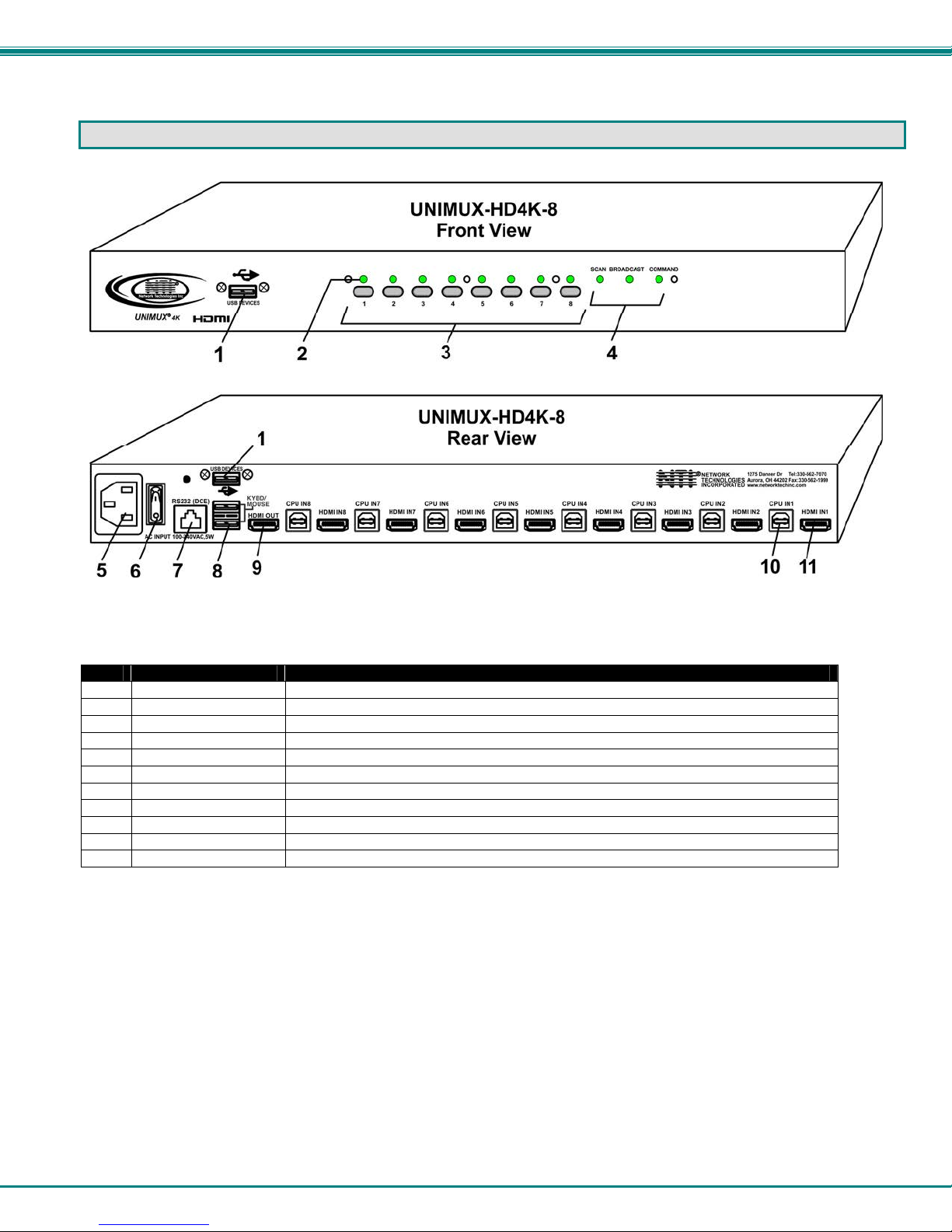
FEATURES AND FUNCTIONS
Item Type Description
1 USB Type A Female Transparent USB port for connecting low-, full-, or high-speed USB 2.0 devices
2 LEDs For visual indication of connection between the user and a specific CPU.
3 Switches Push to manually switch to a specific CPU or change the switch operating mode
4 LEDs For visual indication of switch operating mode
5 IEC Connector For attachment of country-specific power cord
6 Power Switch To control the ON/OFF function of the switch
7 RJ45 Female RS232 (DCE) connection for attachment of RS232 control cable
8 USB Type A Female For connection of user USB device(s)
9 HDMI Female For connection of user monitor cable
10 USB Type B Female For connection of USB device cable from CPUs
11 HDMI Female For connection of video cable from CPUs
NTI UNIMUX SERIES 4K VIDEO USB KVM SWITCH
3
RACKMOUNTING INSTRUCTIONS
This NTI switch was designed to be mounted to a rack or to sit on a desktop. It includes rackmount ears to make attachment to a
rack easy, and rubber feet to be applied to the bottom of the case if it will instead sit on a flat surface. If this will sit on a flat
surface, simply apply the rubber feet to the bottom of the case in each of the 4 corners.
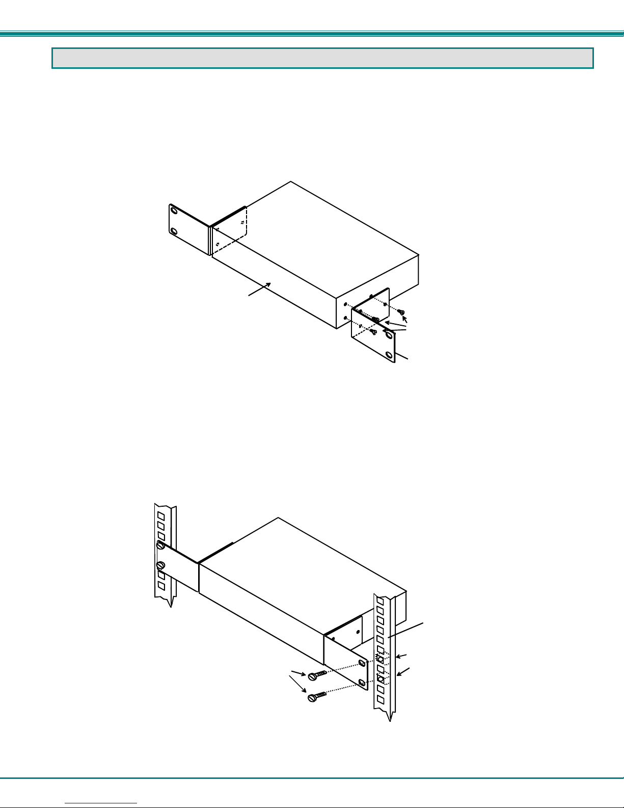
To Mount to a Rack
1. Attach the ears to the switch using the 6-32x3/16" flat Phillips-head screws (6) provided as shown in the illustration below.
The holes in the ears should line up with pre-threaded holes in the sides of the NTI switch. Tighten the screws securely.
Figure 1- Secure rackmount ears to switch
2. Install 4 captive nuts (not provided) to the rack in locations that line up with the holes in the mounting ear on the NTI switch.
3. Secure the NTI switch to the rack using four 3/16" diameter screws (not provided). Each screw should be of sufficient length
to go completely through the NTI mounting ear, rack frame and fully engage all threads in the captive nut. Be sure to
tighten all mounting screws securely.
4. Attach all cables securely to the switch and where necessary supply adequate means of strain relief for cables.
Figure 2- Secure switch to a rack
6-32x3/16"
Flat Head
Screws
(Provided)
Rackmount Ear
NTI Switch
Front of Switch
Captive Nuts
3/16" Diameter Screws
Rack
(not provided)
(not provided)
NTI Switch
NTI UNIMUX SERIES 4K VIDEO USB KVM SWITCH
4
INSTALLATION
1. It is not necessary to turn the CPUs or monitors OFF during this installation.
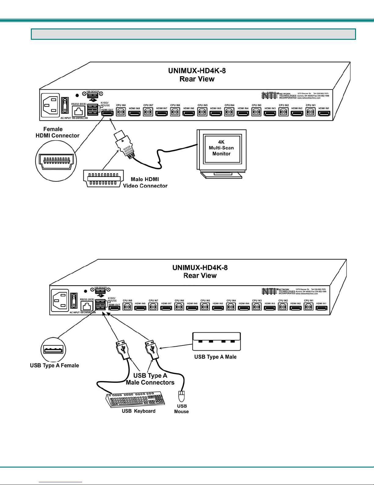
2. Connect the cable from a monitor to the HDMI connector labeled “HDMI OUT” on the UNIMUX (See Fig. 3 below.)
Figure 3- Connect a VGA multi-scan monitor
3. Connect the male USB type A connector on the keyboard cable to either one of the two USB type A female connectors
labeled "KYBD/MOUSE" on the rear panel of the UNIMUX.
4. Connect the male USB type A connector on the mouse cable to the remaining USB type A female connector labeled
"KYBD/MOUSE".
Figure 4- Connect the device(s)
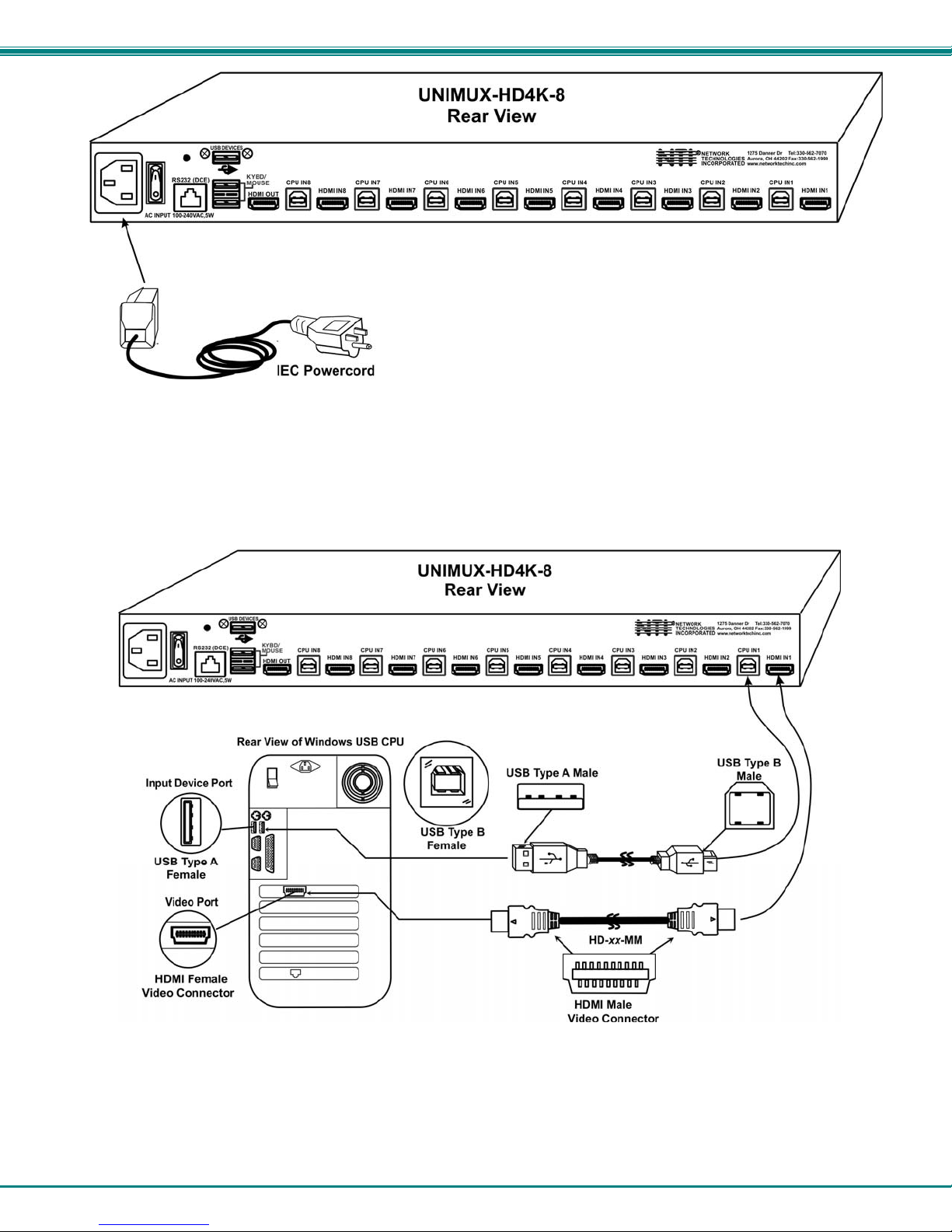
5. Connect the AC line cord to the UNIMUX. (See Fig. 5 below.)
NTI UNIMUX SERIES 4K VIDEO USB KVM SWITCH
5
Figure 5- Connect the AC line cord
6. Connect each CPU to the USB switch using a HD-xx-MM video and USB Type A-B device cable – REQUIRED
(not supplied). (See Fig. 6 below.)
7. Group the input device and monitor interface cables from each CPU, making sure that cables from the first CPU are
connected to the UNIMUX at connectors "CPU IN1" and "HDMI IN1". Cables from the second CPU should
connect to "CPU IN2" and "HDMI IN2" connectors...etc.
Figure 6- Connect each CPU

NTI UNIMUX SERIES 4K VIDEO USB KVM SWITCH
6
RS232 Connection
If the RS232 is going to be used, connect one end of the CAT5 patch cable (supplied) to the port labeled “RS232” on the rear of
the UNIMUX. Plug the other end of the CAT5 cable into the RJ45-to-DB9 adapter supplied, and connect the adapter to the
RS232 port on the control terminal. Follow the instruction under “RS232 Control” on page 16 for configuration and use of the
RS232 control feature.
Figure 7- Connect Terminal for RS232 Control
NTI UNIMUX SERIES 4K VIDEO USB KVM SWITCH
7
Power-Up Sequence
The UNIMUX can be powered at any time.
The CPUs can be powered at any time although if a CPU needs a keyboard and/or mouse at power-ON it should be powered
after connecting to and powering-ON the UNIMUX.
USB input devices (keyboard and mouse) can be hot plugged to and from the UNIMUX at any time.
Immediately after powering ON the UNIMUX, the following
splash screen will appear on the monitor:
Once the splash screen goes away, the UNIMUX is booted up
and the monitor will display the desktop image for the connected
CPU. The user can continue with normal operation of the
connected CPU.
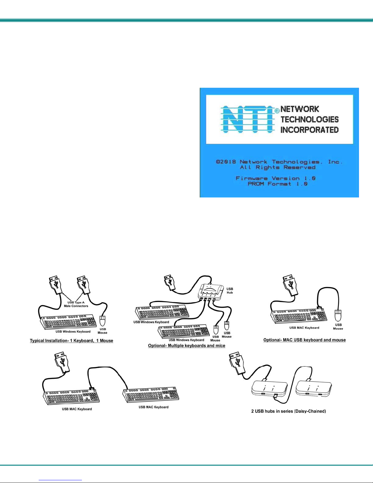
Limitations
Only USB input device or hub cables can be connected to the UNIMUX at the USB Type A female ports labeled
"KYBD/MOUSE". (See Features and Functions on page 2, item 8.)
A USB hub (single or multi-port) can be used provided only USB input devices are plugged into it.
Only a USB Windows keyboard or USB mouse may be connected to the USB port on a USB MAC keyboard
A maximum of 7 devices (including hubs) may be connected to the UNIMUX directly.
See Figure 8 for some examples of input device combinations that can be used with the UNIMUX.
Figure 8- Compatible device combinations

NTI UNIMUX SERIES 4K VIDEO USB KVM SWITCH
8
USING THE UNIMUX SWITCH
Once the UNIMUX is properly connected, the UNIMUX will enable a connection to be made between the CPUs attached to its
VIDEO and CPU ports and the monitor and input devices attached to the MONITOR and DEVICES ports. The LEDs on the
control panel of the UNIMUX will illuminate depending on which port (and corresponding CPU) is being connected to the monitor
and input devices.
The UNIMUX can be controlled by four methods:
front control panel using touch-switches and LEDs
keyboard control through Command Mode
mouse clicks from within some menus of Command Mode
RS232 commands
Front Panel Control
There is a touch-switch and LED on the front panel of the UNIMUX for each CPU the switch will connect the monitor and
input devices to. Pressing any touch-switch on the front panel of the UNIMUX will connect the corresponding CPU to the monitor
and input devices.
Holding down any front panel touch-switch for more than 2 seconds will cause the UNIMUX to cycle through all modes of
operation including COMMAND, BROADCAST, SCAN, and NORMAL (described in "User Access Functions" beginning on page
9). The three MODE LEDs on the front panel indicate which mode is selected. Release the touch-switch when the LEDs indicate
the desired mode. When no mode LEDs are illuminated the user is in Normal Mode controlling directly the CPU to which the user
is connected through the UNIMUX.
Keyboard Control
Keyboard control of the UNIMUX can be achieved using Command Mode (only from the keyboard attached to the
"KYBD/MOUSE" ports)- operated using the keyboard and mouse in conjunction with OSD menus superimposed onto the monitor.
By pressing <Ctrl> + < ` > (accent key), the user can enter Command Mode. Once in Command Mode, typing a series of
commands will cause the UNIMUX to connect the user to any one CPU connected to the switch. Pressing the <Esc> key will exit
Command Mode.

NTI UNIMUX SERIES 4K VIDEO USB KVM SWITCH
9
USER ACCESS FUNCTIONS
Introduction
The OSD menu enables a user to name the CPUs connected to the UNIMUX and connect to them using that name from a single
keyboard and mouse. The OSD is positioned on the user's monitor, displaying 8 CPU names at a time. The screen can be used
for switching as well as editing the CPUs’ names. Through the OSD menu, the user can operate the UNIMUX to have the switch
cycle through 3 extended modes of operation: COMMAND, BROADCAST, and SCAN . Three LEDs on the front panel indicate
when these modes are enabled.
Command Mode
When entering the Command Mode from the keyboard using the <Ctrl> + <`> (accent key), the OSD menu will automatically
appear on the monitor in addition to illuminating the COMMAND indicator LED on the USB KVM switch. This provides a visual
way to control the UNIMUX.
Navigation
Keyboard Key Action
Up/Down Arrow Select previous or Next port (while in the Port List)
Page Up/Down Advance to previous or to the next page of the Port List
Home Select the first port in the displayed port list
End Select the last port in the displayed port list
<number> Select and switch to Port Number
Enter Execute that selection
Shift-Tab Move to previous field in the menu
Tab Move to next field in the menu
Space Toggle the selection of the highlighted field
F1 Bring up the Help Menu (see Figure 10)
Esc Back up in the menu to the previous page or Exit the OSD menu
The mouse can also be used to control the UNIMUX within the Command Mode menu.
The mouse cursor can be moved to anywhere on the OSD menu. Text in blue is selectable. The user
can then single-click the left mouse button to make a selection, double-click to perform that function.
Ports listed on the screen can be selected by moving the cursor onto that port and clicking. If the USB Device
Reminder is enabled, an additional press of the <Enter> key will be needed (unless you press <Esc> and cancel the
change).
To scroll through the displayed ports on the screen simply click on the up and down arrows located to the right of the
port names displayed.
Figure 9- Port List (Main Menu)
Note: The user must
exit Command Mode
to type to a CPU.
To exit Command
Mode, either hold
down any touch-
switch on the front
panel for more than
2 seconds, mouse
click on "Exit" OR
press <ESC> on the
keyboard.
Click to sort b
y
p
ort numbe
r
Click to sort al
p
habeticall
y
Click to scroll

NTI UNIMUX SERIES 4K VIDEO USB KVM SWITCH
10
To change the way the port list is displayed, the user can click on the "#" sign to have the list displayed numerically, or click in
"Name" to have the list displayed alphabetically. If the user decides to rename the ports to something easy to remember, listing
the alphabetically may be the most desired setting.
Figure 10- Help Menu
Settings Menu
From the Settings Menu the user can quickly change the status of the major functions in the UNIMUX.
Figure 11- Settings Menu
The user can change the status of Scan Mode and Broadcast Mode between Disabled (red text) and Enabled (green text). Click
on the status indicated to toggle it.
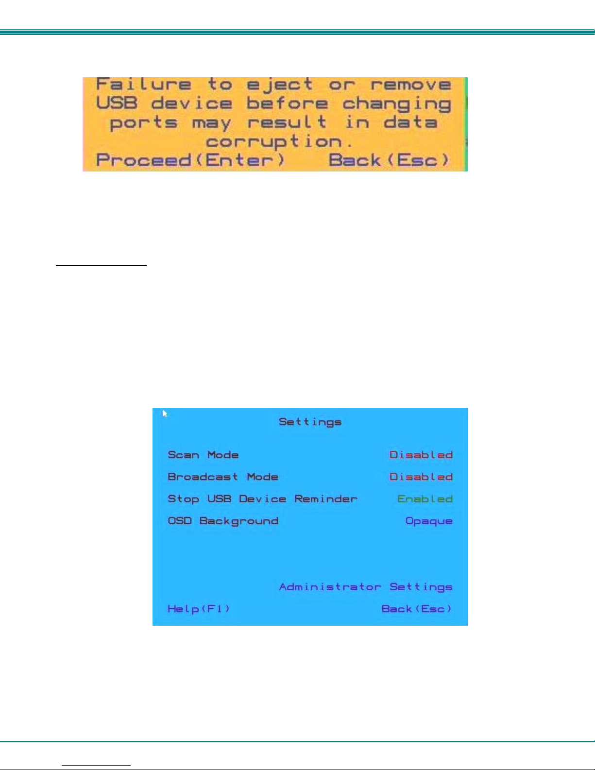
The user can enable or disable the "Stop USB Device" Reminder notice. While enabled, any time the user attempts to change to
a different port number, a warning message will pop up forcing a decision to either proceed with or cancel the attempt. This
provides opportunity for the user to properly eject a USB flash drive or any other device that may be harmed by an abrupt loss of
connection between the user and the PC the flash drive is connected to.
NTI UNIMUX SERIES 4K VIDEO USB KVM SWITCH
11
To respond to the Stop USB Device warning, either click "Enter" or "Esc" with the mouse, or use keyboard keys.
Figure 12- Stop USB Device Reminder warning
From the Setting Menu the user can also toggle the OSD menu to either be Opaque (have solid color) when on the display, or to
be translucent (see-through). Click on the setting to toggle it.
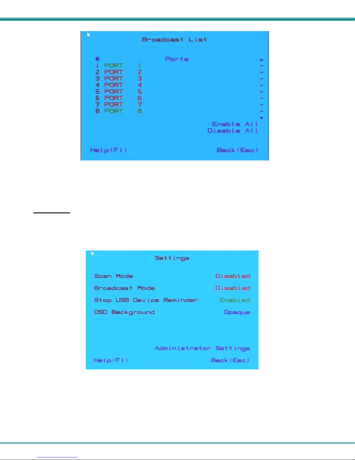
Broadcast Mode
Broadcast Mode enables the user to select specific ports (see Figure 14) to be active in Broadcast Mode. Only the selected ports
will receive keyboard messages in Broadcast Mode.
To activate or deactivate Broadcast Mode from the Command Mode menu, from the main menu click on Settings. From the
Settings menu, click to display either Disabled (deactivate) or Enabled (activated).
Broadcast Mode enables the user to type characters to more computers simultaneously. From the Administrator Settings-
Broadcast List menu (see page 19) the user can edit the list of ports that receive data in Broadcast Mode. A port doesn’t receive
broadcast data the port is not in the Broadcast Mode list
Note: The user must type somewhat slowly when in Broadcast Mode (less than 20 wpm).
Note: While in Broadcast Mode the mouse will not work.
Figure 13- Settings Menu
NTI UNIMUX SERIES 4K VIDEO USB KVM SWITCH
12
Figure 14- Broadcast List
From the Broadcast List, click on a port number to toggle its status. Ports displayed in green are included in the broadcast, ports
in red are not. The quickly select all ports, click on "Enable All". To quickly deselect all ports, click on "Disable All".
Selections are automatically saved.
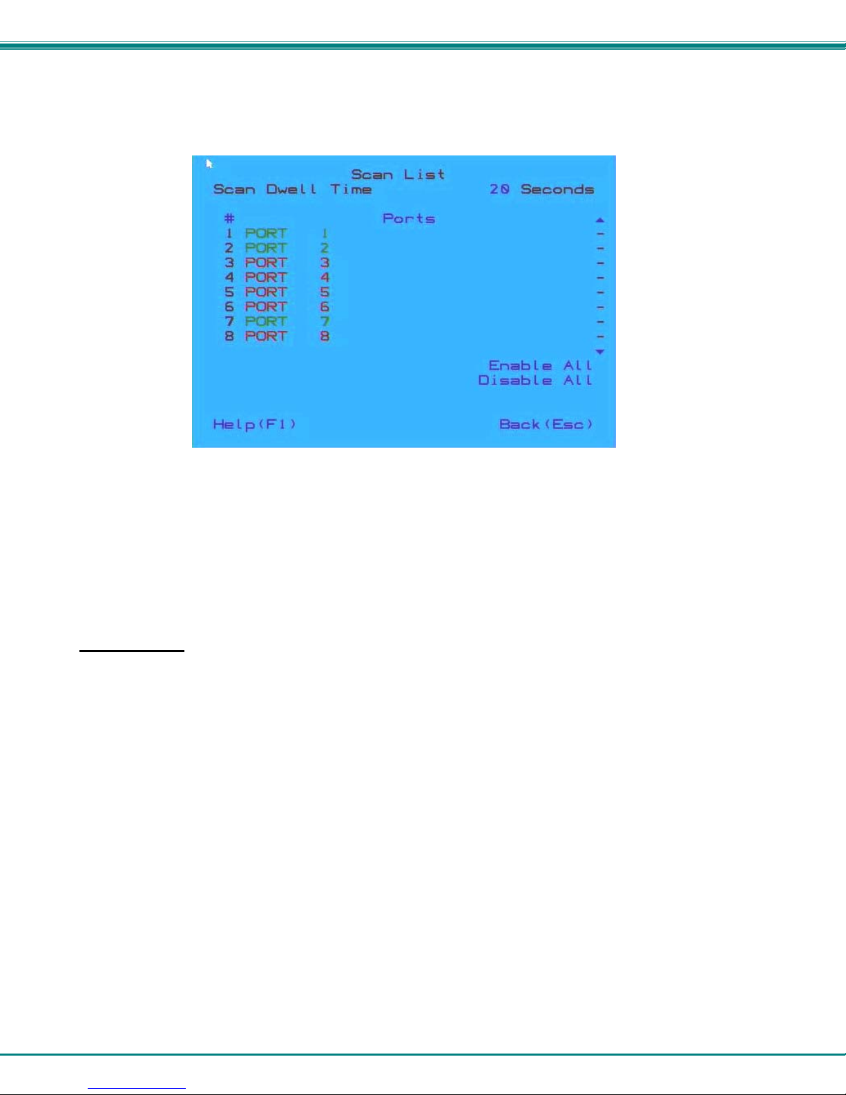
Scan Mode
Scan Mode enables the user to select specific ports (see Figure 16) to be active in Scan Mode. Only the selected ports will be
scanned in Scan Mode.
To activate or deactivate Scan Mode from the main menu click on Settings. From the Settings menu, click to display either
Disabled (deactivate) or Enabled (activated).
Figure 15- Settings Menu
When in Scan Mode the switch scans to each port selected in the Scan List. (The SCAN LED on the front panel will illuminate and
remain ON while in Scan Mode.) Scan mode will connect to selected ports, whether those ports are powered ON or not. The
ports with the CPU powered-ON remains active while in use until it becomes idle for the configured dwell time (Figure 16) (default
time-out period is 15 seconds) before switching to the next selected CPU port. See Command Mode section above for configuring
the scan dwell time.
NTI UNIMUX SERIES 4K VIDEO USB KVM SWITCH
13
Note: The keyboard and mouse must remain idle for the full scan dwell time before the switch selects the next active
port.
Figure 16- Scan List
From the Scan List, click on a port number to toggle its status. Ports displayed in green are included in the scanned, ports in red
are not. To quickly select all ports, click on "Enable All". To quickly deselect all ports, click on "Disable All".
Selections are automatically saved.
Click on the number across from "Scan Dwell Time" to select the field and enter a number between 0 and 255 (default is 15) to
configure the length of time the connection will remain with a CPU before switching to the next CPU while the UNIMUX is in Scan
Mode.
Normal Mode
When the UNIMUX is not in Command, Broadcast, or Scan mode and all of the UNIMUX mode LEDs are OFF, the user is in
Normal Mode, controlling the CPU to which the user is connected through the USB KVM switch.

NTI UNIMUX SERIES 4K VIDEO USB KVM SWITCH
14
Administrator Settings
The Administrator Settings menu provides access to specific administrative functions of the UNIMUX. From the Main Menu
select Settings, then Administrator Settings.
Figure 17- Administrator Settings
Click the Port Name List to bring up a page where the names displayed for the UNIMUX and for each port can be edited.
Clicking on the Port Name List or Scan List will bring up the list of ports to be set to be affected by Broadcast and Scan modes
(pages 11 and 12)
NTI UNIMUX SERIES 4K VIDEO USB KVM SWITCH
15
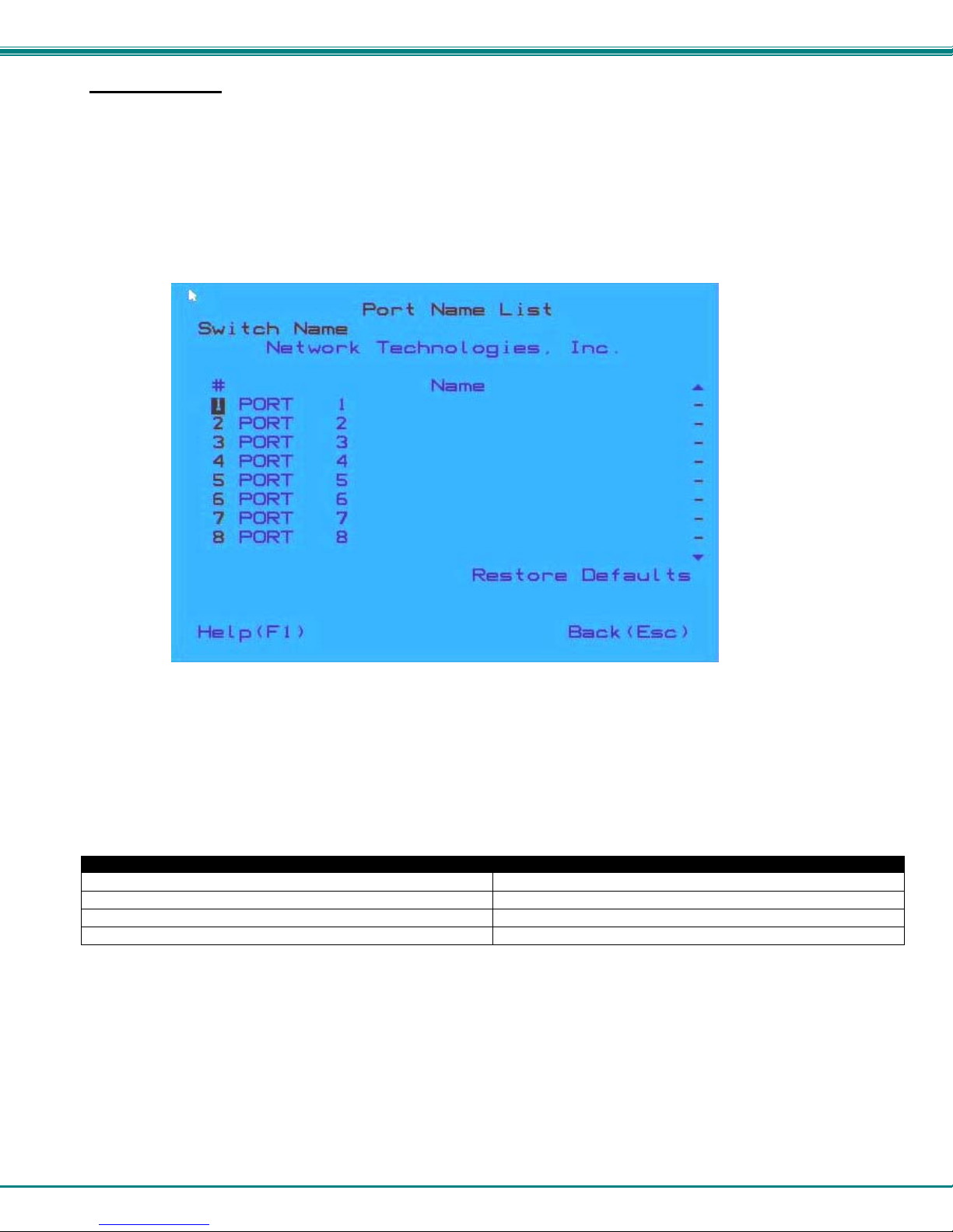
Port Name List
The Port Name List is provided to enable the user to edit the names of the ports and switch. Port names and the switch name
can be up to 30 characters in length. The user can customize the UNIMUX to make switching to frequently used ports more
easily. The Port Name List is accessed from the Administrator Settings menu (page 14).
Figure 18- Port Name List
To quickly return the switch to factory settings for the switch name, port names, and all configured settings, click on "Restore
Defaults".
To Edit the Switch name and Port Names:
Using the Keyboard: Using the Mouse:
1.Press <Tab> to move between fields 1.Click on the field to select it
2.Press <Enter> to select a field to edit 2.Type the text to be used
3.Type the text to be used 3.Press <Enter> to save it
4.Press <Enter> again to save it
Editing keyboard keys for name fields include: Backspace, Delete, Right Arrow, Left Arrow, Home, End and Insert.

NTI UNIMUX SERIES 4K VIDEO USB KVM SWITCH
16
RS232 CONTROL
RS232 enables the UNIMUX to be remotely controlled via RS232. To control the UNIMUX via RS232 the user has three options:
write a program that runs on a PC using the Command Protocol (page 16)
use the NTI Switch Control Program (page 17)
use the SerTest program (page 18)
RS232 Connections and Configuration
Remote Connection
The RS232 Interface (optional) is designed to meet the RS232C standard and can be controlled from any CPU or other controller
with an RS232 communications port. The pin-out for the RJ45 connector on the unit is as follows:
RS232 (RJ45) CONNECTOR
PIN SIGNAL FUNCTION
1 - No connection
2 - No connection
3 RX+ Receive data (TXD at host)
4 GND Ground
5 - No connection
6 TX+ Transmit data (RXD at host)
7 - No connection
8 - No connection
A 5 foot patch cable and adapter, RJ45-to-DB9 has been provided for connection to most CPUs (see page 6).
Baud Rate
The default application baud rate for the UNIMUX is 115200. This can be changed to 1200,2400,4800,19200,38400,57600 or
115200 using RS232 control commands.
Note: When performing a firmware upgrade, the baud rate will always be 115200, regardless of what the application baud
rate has been set to.
Command Protocol
RS232 commands supported by the unit are defined below. All command strings should be terminated with a <CR> (carriage
return). When a command is sent, the entire string is echoed back along with a response from the addressed unit as shown in the
command definitions. All characters in the command string should be upper case, and all numbers below 10 should have a
leading 0 (ex: 1 = 01).
Figure 19- RS232 Communication Illustrated
CS 01,01,03<CR> CS 01,01,03<CR>
(COMMAND RECEIVED)
(RESPOND)
* <CR>
(COMMAND SENT)
(RESPONSE RECEIVED)
CS 01,01,03<CR>
* <CR>
CPU SWITCH AT UNIT ADDRESS 01
RS232
RS232
(ECHO)
CS 01,01,03<CR>
Table of contents
Other NTI Switch manuals

NTI
NTI SERIMUX-SECURE-x User manual

NTI
NTI RACKMUX-V15-N-PRIMUX User manual

NTI
NTI SE-15V-xx-L User manual

NTI
NTI SM-nXm-DVI-LCD User manual

NTI
NTI Splitmux-C5HDR-4LC User manual

NTI
NTI SM-nXm-AV-LCD User manual

NTI
NTI SE-4K18GB-4RS User manual

NTI
NTI USBV-x User manual

NTI
NTI UNIMUX Series User manual

NTI
NTI VEEMUX SM-nXm-C5AV-LCD User manual

NTI
NTI SERIMUX-S-x User manual

NTI
NTI RACKMUX-DS17-NT-4DVIHD User manual

NTI
NTI SM-16X16-HD4K Manual

NTI
NTI UNIMUX-nXm-UHD User manual

NTI
NTI UNIMUX-USBV-2 User manual

NTI
NTI UNIMUX-USBV-xHD User manual

NTI
NTI KEEMUX-P2-LC Operation manual

NTI
NTI UNIMUX Series User manual

NTI
NTI UNIMUX-DVI-2 User manual

NTI
NTI RACKMUX-V15-4UNV User manual


