Trin & Stor │Installation and Operation Instructions Indirect Water Heaters
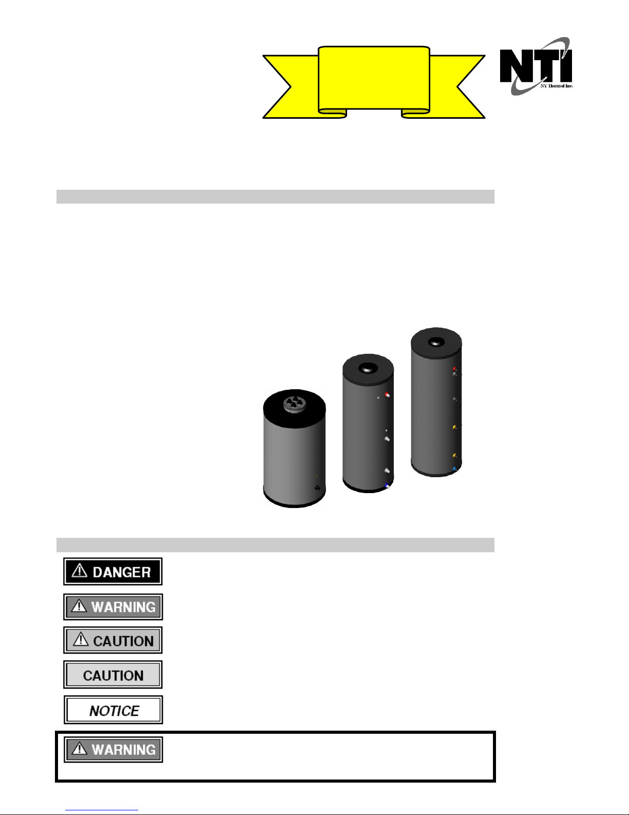
Indirect Water Heater - NTI Trin & Stor Indirect Water Heaters are equipped with a single-walled internal
heat exchanger coil. To maintain the efficient and reliable operation of the heat exchanger, and to avoid heat
exchanger failure, it is critical to ensure the rules and guidelines in this section are followed.
Locate the water heater in an area where leakage from the tank or plumbing connections
will not result in water damage to adjacent areas or lower floors. If such a location is
unavoidable, install a suitable catch pan with a drain under the appliance. This manufacturer is not responsible
for any water damage that may occur in connection with the indirect tank or any of its components.
Temperature and Pressure Relief Valve - Each Indirect comes standard with a factory supplied temperature
and pressure relief valve, sized to ASME specifications and compliant with Standard ANSI Z21.22•CSA 4.4
Relief Valves for Hot Water Supply Systems. The field installed relief valve and discharge piping is to be
mounted on the Indirect Water Heater in accordance with Figures 2-3 and 2-4 and must be accessible for
servicing or replacement. No valve is to be placed between the Relief Valve and the Indirect Water Heater or
Relief Valve and discharge pipe. Install discharge piping as shown in Figures 2-3 and 2-4 and in accordance with
Installation Checklist 2-1. Temperature and pressure relief valve provided with Sol-R-Therm is Watts 100XL-8.
T&P Normal Operation - The relief valve is not intended for constant duty such as
repeated operation due to normal system expansion. If this occurs, correct the situation
by installing a properly sized domestic expansion tank as per the expansion tanks manufacturer’s instructions.
Location - Do not conceal, plug, or remove the relief valve from its designated point of
installation. Failure to comply may result in property damage, personal injury or death.
Tank Sensor - designed for installation into the Thermal-Well of the Trin & Stor Indirect Water Heater; the
Tank Sensor provides a temperature reading of the tank to an NTI-Trinity Tft, Lx or Tx series boiler, eliminating
the need for a separate controller (e.g. the TPI Control Thermostat or other)*. The Tank Sensor incorporates a
UL353 rated thermal cutoff switch designed to open at a temperature of 90ºC (194ºF). Tank Sensor installation
instructions are detailed in Section 3.0.
*NTI-Trinity Ti and Ts series boilers are not designed to accept the Tank Sensor reading, therefore the TPI
Control Thermostat, or other tank thermostat or aquastat, must be used.
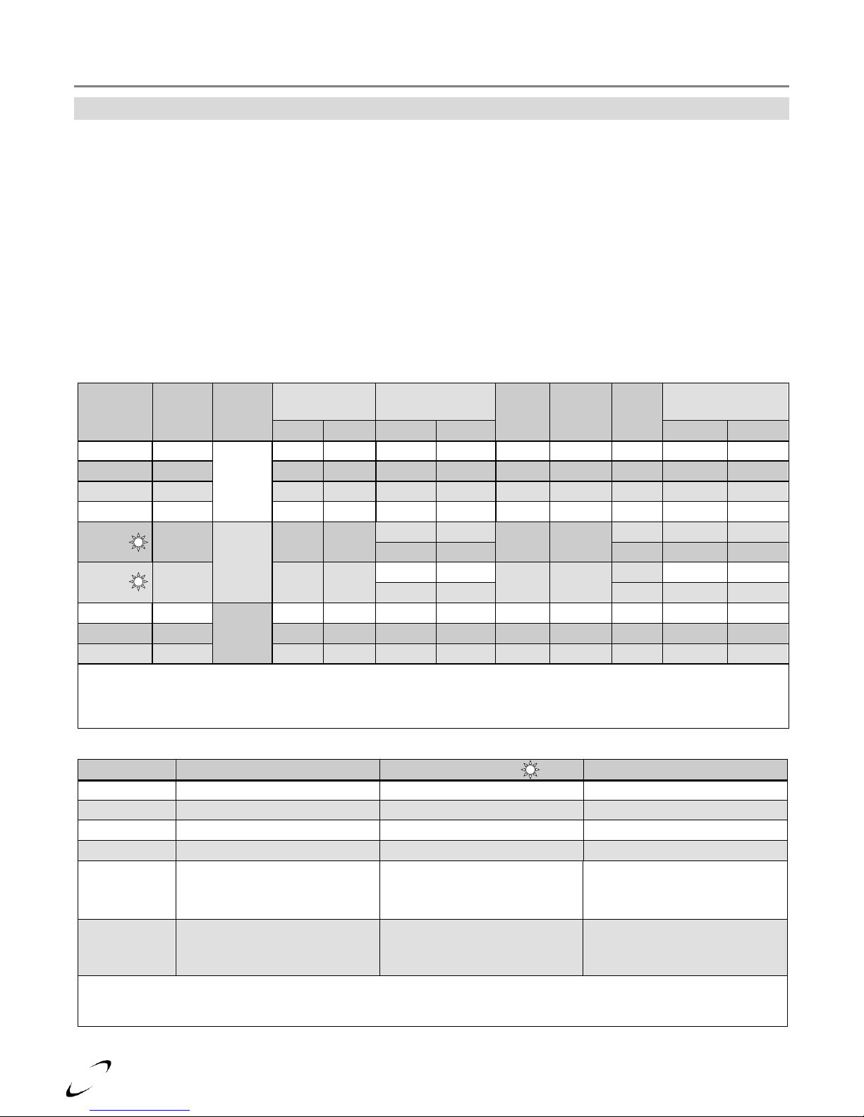
Drain Valve - The Indirect water heater requires a field supplied drain valve to facilitate emptying the tank for
inspection and servicing. Refer to Table 2-4 for drain port size and type.
System Backflow Preventor - Check if a backflow preventor (BFP) is required by local codes. Most plumbing
codes require a thermal expansion control device be installed if a backflow preventor, pressure reducing valve or
check valve is installed on a domestic supply line. If a backflow prevention device is used, then an expansion
tank is mandatory (not optional) and must be installed downstream of any device used to control system thermal
expansion. When using multiple indirects, check if a single BFP is required on the domestic supply or if each
tank requires its own backflow preventor and respective expansion tank. See Figures 2-3 and 2-4.
DHW (Potable Water) Expansion Tank - This manufacturer recommends installing an expansion tank in the
domestic hot water system for the purpose of absorbing the increase in water volume caused by rising water
temperature. If required by local codes, the expansion tank must be suitable for use with potable water and be
sized in accordance with the water volume of the system and the firing rate of the boiler connected to the indirect
water heater. Refer to the expansion tank manufacturer’s literature for proper sizing information.
Isolation Valves –Ensure any valves installed between the expansion tank and indirect
tank inlet are left in the OPEN position during normal operation. Failure to follow these
instructions may result in discharge of the Relief Valve and result in property damage or personal injury.
Thermostatic (Anti-Scald) Mixing Valve - A mixing valve is recommended on branches supplying low
temperature water to endpoint plumbing fixtures when domestic hot water is stored above 46°C (115°F).
Temperature Limiting Device - When the tank requires water at temperatures higher
than 46°C (115°F), a mixing valve shall be installed to temper the water and reduce the
risk of scalding. Failure to follow these instructions may result in serious injury or death.


 Operation and maintenance instructions")