NTI Trin & Stor ST Series User manual

Trin & Stor
Model Numbers: ST Series
Version Date: 2019-08-19
STORAGE TANK
INSTALLATION AND OPERATION INSTRUCTIONS
Storage companion to a Water Heater or Solar Thermal System
TABLE OF CONTENTS
1.0 INTRODUCTION................................................................................................................2
Trin & Stor Specifications....................................................................................................2
General Installation Requirements .......................................................................................2
I.O.M. Checklists..................................................................................................................2
Safe Temperatures for Potable Water...................................................................................3
2.0 STORAGE TANK PIPING..................................................................................................5
Storage Tank Piping .............................................................................................................5
Connection to a Water Heater...............................................................................................6
3.0 TANK SENSOR...................................................................................................................8
4.0 START UP AND CHECK OUT........................................................................................10
5.0 ANNUAL MAINTENANCE AND INSPECTION ...........................................................10
6.0 PARTS LIST ......................................................................................................................10
HAZARD SYMBOLS AND DEFINITIONS
Danger Sign: Indicates a hazardous situation which, if not avoided, will
result in serious injury or death.
Warning Sign: Indicates a hazardous situation which, if not avoided,
could result in serious injury or death.
Caution Sign plus Safety Alert Symbol: Indicates a hazardous situation
which, if not avoided, could result in minor or moderate injury.
Caution Sign without Safety Alert Symbol: Indicates a hazardous
situation which, if not avoided, could result in property damage.
Notice Sign: Indicates a hazardous situation which, if not avoided,
could result in property damage.
Tanks must be installed by a licensed installer. Improper installation,
use, neglect or abuse of this product will void the warranty.
NTI 84270
ST Series

Trin & Stor │Installation and Operation Instructions Storage Tanks
2
1.0 INTRODUCTION
Trin & Stor Specifications
Table 1-1 Storage Tank Specifications
Model
Storage
Capacity
(US Gal)
Type
Weight (lbs)
The "ST" Series consists of a high performance
stainless steel tank and can be used as a storage
companion to a water heater or solar thermal
system. For the complete NTI Trin & Stor line,
visit www.ntiboilers.com.
Empty
Filled
ST80
80
Stainless Steel
Storage Tank
160
995
ST120
119
175
1275
Table 1-2 Storage Tank Characteristics
Attribute
ST Series
Water Chemistry -
Water used in the
storage tank must meet the water chemistry
limits specified in Table 2-1. Levels outside
the limits may corrode the tank and shorten
its life resulting to damage to tanks and
voiding the warranty.
Tank
stainless steel
Insulation
EPS foam
Jacket
grey plastic
Recommended
Service
Clearances
top
12"
connection side
12"
water heater connections
as required
MAWP
150 psi
Restrictions
Max tank temp
190oF
Max water heater temp
210oF
General Installation Requirements
Generalized instruction and procedures cannot anticipate all situations. For this reason, only a qualified installer
should perform the installation.
Users Responsibility –This manufacturer anticipates the proper installation and care in use of the product. As
with any hot water system, there is a risk of property damage and personal injury inherent in the use. NTI cannot
supervise the installation and therefore makes it a specific condition for the warranty that the customer will
supervise the installation and use of the product to be sure they are performed in accordance with the instructions
and I.O.M. Checklists in this manual. It is the User’s responsibility to maintain the appliance by having it
inspected on an annual basis, serviced as required, and to use the product for the purpose it was intended.
Installers Responsibility –A qualified installer is a licensed person who has appropriate training and a working
knowledge of the applicable codes, regulations, tools, equipment and methods necessary to install a storage tank
or water heater. The Installer assumes all responsibility for a safe installation and that it meets the requirements
of this document, as well as National and local codes.
I.O.M. Checklists
The various Installation, Operation and Maintenance (IOM) Checklists contained in this manual are meant to be
read in conjunction with the details, drawings and safety information to ensure a complete and proper installation.
General Information
1. Review system specifications and characteristics.
2. Know the Water Chemistry and Warranty requirements.
3. Be informed of potential hazards associated with potable water.
DOs & DON’Ts
1. DO NOT install tank close to high temperature appliances or wood stoves as tank jacket is combustible.
2. DO NOT install where there is a risk of property damage in the event of an eventual leak at some
unpredictable time.
3. DO support the entire tank bottom with ¾" plywood (min) if elevating off the floor with blocks.

Storage Tanks Installation and Operation Instructions │Trin & Stor
3
Pre-Installation Checklist
Inspection and Preparation
1. Remove packaging. Inspect for damage during shipping.
2. Package contents should contain the following:
Storage Tank (verify correct model number) Manual
Temperature and Pressure Relief Valve (150psi) Warranty Card
Locating the Tank
1. Solid foundation, dry location, near water heater.
2. Leave room to service storage tank and controls.
3. Ensure there is sufficient room for piping and servicing the storage tank and water heater.
4. Area free of flammable liquids or combustible vapors.
5. Ensure the location chosen for the tank is capable of supporting the tank when filled with water.
6. Locate in room where temperature never drops below 50oF (10oC).
Water Damage Protection
1. Where possible, locate the storage tank in an area where potential leaks from the tank, fittings, connections, or
relief valve will not result in water damage to adjacent areas or lower floors.
2. If the area surrounding the tank is susceptible to water damage, install a catch pan c/w drain under the tank.
Water Damage - This manufacturer is not responsible for any water damage that may
occur in connection with the storage tank or any of its components.
Intended Purpose - This appliance is not intended to convey or dispense water for
human consumption such as drinking or cooking.
Annual Service - Failure to have the Storage Tank properly serviced and inspected on a
regular basis by a qualified technician may result in property damage or serious injury.
Safe Temperatures for Potable Water
Two factors used to determine safe hot water temperatures are Legionella and scalding. Potable water needs to
be stored at temperatures hot enough to limit the growth of Legionella, yet be cool enough to prevent scalding.
Since both hazards present a potential risk to the user, they must be monitored and controlled. Table 1-4
indicates how water temperature affects Legionella bacteria and contributes to scald injury. Use of a thermostatic
mixing valve in the storage tank plumbing system can help protect against both of these hazards. By storing
potable water at higher temperatures, bacteria growth is controlled, while still providing high temperature water
for dishwasher applications and low temperature water for bathing. Before proceeding, read the following
carefully and take all necessary precautions to avoid potential illness and/or injury that can result from
Legionella or scalding hazards.
Legionella Hazard - This bacteria is naturally occurring in surface water and ponds. It
can also be found in man-made water systems around the world such as water storage
tanks, water distribution systems, fountains, hot tubs, humidification systems, refrigeration systems and grocery
produce misters. Health authorities agree that Legionella bacteria most often enter the lungs due to aspiration
when contaminated water spray is breathed in as opposed to ingesting drinking water contaminated with the
bacteria. Typical illnesses attributed to Legionella include flue like symptoms (Pontiac Fever) and a potentially
fatal type of pneumonia (Legionnaires’ disease). Failure to follow instructions may result in illness or death.
Contributing Factors to Legionella - Experts acknowledge that Legionella is an identified risk in most water
systems. Although eradicating Legionella is improbable, precautions can be taken to control and monitor
conditions that promote bacteria growth. According to the World Health Organization (WHO); American
Society of Heating, Refrigeration, and Air-conditioning Engineers (ASHRAE); Canada Safety Council (CSC);
and Centers for Disease Control (CDC), contributing factors to the growth of Legionella in potable water
systems include:

Trin & Stor │Installation and Operation Instructions Storage Tanks
4
Minerals and nutrients present in the source water and systems materials
Stagnation or low flow characteristic of dead ends in distribution piping systems and storage tanks
Scale, corrosion, and bio film
Tepid water in cold water lines
Water storage temperatures optimal for bacteria growth
Chlorine concentration
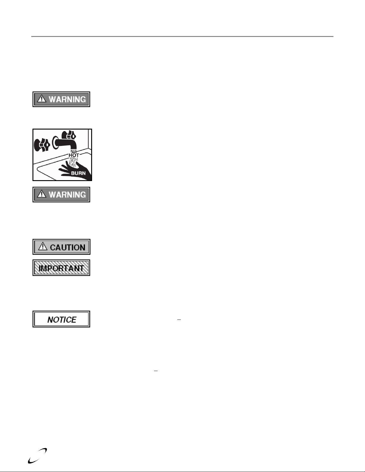
Scald Hazard - Hotter water increases the risk of scald injury. There is a hot water scald
potential if the storage tank thermostat is set too high. Before changing the temperature
setting on the tank thermostat, refer to the thermostat manufacturers recommended settings. Failure to follow
these instructions may result in serious injury or death.
A scald injury can occur when hot steam or liquid makes contact with one or more layers
of skin. Scald severity (degree of burn) is directly impacted by exposure time and
temperature. Refer to Table 1-4. The following basic precautions are common sense:
Young children and elderly adults burn more quickly and should use cooler water.
Never leave a child alone while drawing water in a bathtub.
Test the water temperature before bathing or showering.
Turn cold water on first, then add hot water until the temperature is comfortable.
Thermostatic Mixing Valve - When the system requires water at temperatures higher
than required for other uses, such as high temperature applications typically greater than
46oC (115oF), a means such as a thermostatic mixing valve shall be installed to temper the water for those uses
in order to reduce scald hazard potential. Anit-scald devices such as a thermostatic mixing valve allows potable
water to be stored at a higher temperature to limit bacteria growth, and allows water at the tap to be delivered at
a lower temperature to prevent scalds. Failure to follow these instructions may result in serious injury or death.
This appliance is not intended to convey or dispense water for human consumption such
as drinking or cooking.
Legislation and Guidelines - At the time this document was written, standards and
guidelines regulating the prevention of Legionella in the United States and Canada were
mostly voluntary. The American Society of Heating, Refrigerating and Air-Conditioning Engineers, Inc.
(ASHRAE) is currently in the process of converting its guideline entitled "Minimizing the Risk of Legionellosis
Associated with Building Water Systems" (ASHRAE Guideline 12-2000) into an official standard. Consult with
your local authorities as to recommended guidelines for controlling Legionella in potable water systems.
Storing water at temperatures >140°F may not be permitted in some States, so check
with the authorities having jurisdictions. In Canada, recent changes to the National
Plumbing Code requires that domestic hot water be stored at or above 61oC (140oF) and
then mixed down to safe temperatures at the tank outlet.
General Guidelines - In the absence of a National standard or local codes, the following are general guidelines
for “good practice” on maintaining, monitoring and operating your potable water system:
Store domestic hot water at temperatures > 61oC (140oF).
Store and distribute cold water at temperatures below 20oC (68oF).
System supply for uses other than high temperature applications typically greater than 46oC (115oF) shall be
equipped with a thermostatic mixing valve on the hot water outlet to reduce potential scald hazards.
Clean aerators and nozzles on water fixtures on a regular basis to reduce scale build-up.
Clean storage tanks and remove sediment. Flush storage tanks and piping systems regularly for 10-30
minutes at high water temperatures (depending on guidelines used) to rid the system of sediment and scale
that develops, typically in the bottom of storage tanks where water temperature is coolest; and piping runs
where water can stagnate.
Abandoned water lines should be capped off at the distribution main, not at the most convenient place.

Storage Tanks Installation and Operation Instructions │Trin & Stor
5
Avoid dead-ends in piping system. If unavoidable, provide a drainage port in these areas at the lowest point
to flush out stagnant water regularly.
Insulate Domestic Hot Water recirculation lines and keep pipe runs as short as possible.
Recommend annual water testing of water in your tank and piping system(s) to monitor water conditions.
Keep a maintenance record of when your water heater and storage tank were cleaned, piping systems
flushed and who did the service work.
Table 1-4 How Water Temperature relates to Legionella and Scald Hazard
Water Temperature 1
Legionella Bacteria 1
Water Temperature 2,5
Exposure Time vs Burn 5
158-176oF
70-80oC
Disinfection range
158oF
70oC
1 second - 2nd or 3rd degree burn
140-149oF
60-65oC
Bacteria die within minutes
140oF
60oC
5 seconds - 2nd or 3rd degree burn
122-131oF
50-55oC
Bacteria die within hours
131oF
55oC
5 seconds - 1st degree burn
68-113oF
20-45oC
Bacteria thrive and multiply
122oF
50oC
1 minute - 1st degree burn
below 68oF
below 20oC
Bacteria is dormant
111oF
44oC
5 hours - 1st degree burn 3,4
Notes:
1 Published by Chartered Institute of Plumbing and Heating Engineering, Databyte series, "Safe Hot Water Temperatures".
2The elderly and small children are susceptible to bad burns at shorter exposure times than listed in this table.
3A thermostatic mixing valve should be installed on DHW storage tanks when outlet temperatures exceed 115oF [46oC].
4Typical water temperature for bathing or showering range between 98-113oF [37-45oC].
5Temperature-Time-Burn Chart published by John Hopkins University, excluding notes.
2.0 STORAGE TANK PIPING
Failure to follow the instructions provided in this section will void your NTI warranty
and may result in property damage.
Storage Tank Piping
Tank connection ports are identified in Figure 2-1 and dimensioned in Tables 2-3 and 2-4 and their function is
described in detail below. For multiple storage tanks, pipe the tanks in parallel using equal pipe lengths between
each tank and a common tee to ensure equalized draw.
Energy Efficiency - Although the NTI Trin & Store Storage Tank is well insulated, insulating long pipe runs
can improve the system efficiency by conserving energy and reducing standby losses.
System Preparation - Prior to connecting plumbing to the storage tank, flush the entire system to ensure it is
free of harmful impurities. Check the water composition of the domestic water supply to determine if it is within
the water chemistry limits specified in Table 2-1. If levels are outside the acceptable limits, consult a qualified
water treatment expert about treatment options for domestic water.
Damage to tanks resulting from water chemistry levels outside the ranges specified in
Table 2-1 can cause corrosion, shorten the life of the tank, and void the warranty.
Table 2-1 Water Chemistry Requirements
Characteristic
"ST" series
Flushing the Storage Tank - Many solder
fluxes can severely corrode stainless steel.
Once piping connections are completed, flush the storage tank by
drawing at least three (3) times the tank’s volume through the
storage tank prior to heating domestic water in the tank. Failure to
flush the tank will void the warranty.
PH
Min
6.0
Max
8.0
Chloride (ppm)
Min
0.0
Max
80.0
System Components - As a minimum, a properly installed system will include the following major components
identified in Table 2-2. It is the responsibility of the installing contractor and system designer to consider all
aspects of a proper system design including compliance with local codes, including additional components
required for prevention of thermal-siphoning (i.e. heat traps), isolation valves, drain and purge valves, etc.

Trin & Stor │Installation and Operation Instructions Storage Tanks
6
Table 2-2 Major Component Checklist
Factory Supplied Components
Field Supplied Components
Storage Tank
System Backflow Preventor1
Temp & Pressure Relief Valve (150PSI)
DHW (Potable Water) Expansion Tank1,2
Tank Sensor
Thermostatic (Anti-Scald) Mixing Valve
Drain Valve
Potable Water Circulator (as required)
Control Thermostat (when Tank Sensor cannot be used)
Notes:
1Check if required by local codes.
2Expansion Tank is mandatory if using a System Backflow Preventer.
Temperature and Pressure Relief Valve - Factory supplied T&P relief valve, sized to ASME specifications
and compliant with Standard ANSI Z21.22•CSA 4.4 Relief Valves for Hot Water Supply Systems.
T&P Normal Operation - The relief valve is not intended for constant duty such as
repeated operation due to normal system expansion. If this occurs, correct the situation
by installing a properly sized domestic expansion tank as per the expansion tanks manufacturer’s instructions.
Location - Do not conceal, plug, or remove the relief valve from its designated point of
installation. Failure to comply may result in property damage, personal injury or death.
Drain Valve - The Storage tank requires a field supplied drain valve to facilitate emptying the tank for
inspection and servicing. Refer to Table 2-4 for drain port size and type.
System Backflow Preventor - Most plumbing codes require a thermal expansion control device be installed if a
backflow preventor, pressure reducing valve or check valve is installed on a domestic supply line. If a backflow
prevention device is used, then an expansion tank is mandatory (not optional) and must be installed downstream
of any device used to control system thermal expansion. When using multiple storage tanks, check if a single
BFP is required on the domestic supply or if each tank requires it’s own backflow preventor and expansion tank.
DHW (Potable Water) Expansion Tank - This manufacturer recommends installing a potable water expansion
tank in the hot water system for the purpose of absorbing the increase in water volume caused by rising water
temperature. If required by local codes, the expansion tank must be sized in accordance with the water volume of
the system. Refer to the expansion tank manufacturer’s literature for proper sizing information.
Thermostatic (Anti-Scald) Mixing Valve - A mixing valve is recommended on branches supplying low
temperature water to endpoint plumbing fixtures when domestic hot water is stored above 46°C (115°F).
Temperature Limiting Device - When the tank requires water at temperatures higher
than 46°C (115°F), a mixing valve shall be installed to temper the water and reduce the
risk of scalding. Failure to follow these instructions may result in serious injury or death.
Connection to a Water Heater
The NTI Trin & Stor Storage Tanks are intended to be heated by an external hot water heater or solar thermal
system and supplied directly to the storage tank using connection ports 4 and 5. See Figure 2-1.
High Temperature Applications - Trin & Stor Storage Tanks are specifically designed
for low temperature applications [<100oC (210oF)] and are NOT intended to be used as a
pool heating system or in conjunction with high temperature steam producing appliances where water
temperatures could potentially exceed 100oC (210oF). Failure to follow these instructions may damage the tank
resulting in property damage, serious injury or death.

Storage Tanks Installation and Operation Instructions │Trin & Stor
7
Figure 2-1 Storage Tank Dimensions
Installation Checklist
1.
Install piping as per National and local codes.
2.
Mark the water supply for future reference.
3.
Install a thermostatic mixing valve on the hot
water outlet of the storage tank.
4.
Install hot water heater plumbing connections as
per the water heater manufacturer’s instructions.
5.
Install T&P relief valve on tank in accordance
with local codes.
6.
Ensure any valves installed between the
expansion tank and storage tank inlet are left in
the OPEN position during normal operation.
7.
Ensure no valve is installed between the relief
valve and discharge pipe.
8.
Ensure discharge piping material used is rated to
withstand temperatures up to 250oF (120oC).
9.
Direct discharge to a safe area (drain) where hot
water or steam will not cause damage or injury.
10.
Terminate discharge pipe 6"-12" above the
floor. Do not connect discharge pipe directly to
a drain.
11.
Typical discharge pipe diameter ¾". Maximum
pipe length is 15 feet with 2 or less elbows.
12.
Cut discharge end of pipe at a 45oangle to
reduce the risk of being blocked or capped.
13.
Verify with local codes if a backflow preventor
or thermal expansion control device is required.
14.
Install a domestic expansion tank downstream of
the backflow preventor (control device).
15.
Install the domestic expansion tank on the cold
water supply.
16.
Flush the tank thoroughly before filling the tank
in preparation to heat water.
Table 2-3 Storage Tank Dimensions
Filling the Storage Tank
Model
Dimensions (inches)
1.
Thoroughly flush the storage tank by drawing
three (3) times the tank’s volume through it.
A
B
C
D
E
F
G
ST80
72 5/8
59 1/2
59 1/2
11 5/8
10 5/8
2 3/8
23 7/8
2.
Verify water connections completed.
ST120
64 3/4
52 3/8
52 3/8
13 1/4
12 1/4
2 3/8
28 7/8
3.
Close drain valve. Open the highest hot water
faucet.
Table 2-4 Storage Tank Connections
Model
Connection Port Sizes
4.
Open valve on cold water inlet and fill system.
T&P RV
Hot Out
Sensor
HWH In
HWH Out
5.
Fill until a steady stream of water flows from the
hot water faucet.
1
2
3
4
5
ST80
1" F
1 1/2" M
Well
1 1/2" M
1 1/2" M
6.
Close the hot water faucet.
ST120
1" F
1 1/2" M
Well
1 1/2" M
1 1/2" M
7.
Ensure the storage tank is filled and piping is
free of leaks before proceeding to Operational
Checklist in Section 4.0.
General Notes:
- Connections are NPT unless noted otherwise.
- The sensor connection is a friction fit immersion well.

Trin & Stor │Installation and Operation Instructions Storage Tanks
8
3.0 TANK SENSOR
NTI offers an optional Tank Sensor (p/n 84632), which is compatible with all NTI-Trinity Lx series water
heaters; follow the instructions below for proper installation, wiring and water heater control setting adjustments.
The Tank Sensor is NOT compatible with NTI-Trinity Lx series water heaters that are
wired together as part of a multiple water heater cascade (i.e., when they are “Lead-
Lagged” together). When using a Trin & Stor Storage tank with a cascade water heater
system, the TPI Control Thermostat, other thermostat or aquastat must be used.
Installation instructions are included with the TPI Control Thermostat.
Installation Instructions
LOCATE THERMAL WELL
INSERT TANK SENSOR
SECURE TANK SENSOR
Hook wire retainer to the back of the Thermal-Well rib;
pull to ensure it will not fall-out.
Connect to boiler
using field wiring

Storage Tanks Installation and Operation Instructions │Trin & Stor
9
WIRE TANK SENSOR TO WATER HEATER
Figure 3-1 Tank Sensor to Trinity Lx Water Heater
ADJUST TRINITY LX WATER HEATER CONTROL SETTINGS
In order for the Water Heater to operate correctly with the Tank Sensor, some control settings need to be
adjusted. Navigate to the Domestic Hot Water Configuration screen and make the following adjustments to the
settings; see Figure 3-2 (note: you must login before adjustments can be made):
1. Demand switch –change setting to “DHW sensor with On/Off temperatures”
2. Modulation sensor –maintain factory setting of “Outlet sensor”
3. Setpoint –set to the desired Water Heater operating temperature during a DHW demand; should be set
higher than the “Demand Off temperature”. Typical setting = 130⁰F to 190⁰F.
4. Demand On temperature –tank temperature where a DHW demand is initiated, must be set lower than
the “Demand Off temperature. Typical setting = 120⁰F to 175⁰F.
5. Demand Off temperature –tank temperature where a DHW demand is ended, must be set higher than
the “Demand On temperature. Typical setting = 125⁰F to 180⁰F.
Figure 3-2 Trinity Tft & Lx Series Control Adjustments
For more information on adjusting the Water Heater control settings, refer to: APPENDIX A
of the Trinity Lx Water Heater Instruction Manual.
Adjust to desired
tank temperature
Adjust to desired
boiler temperature
Set as illustrated
Must be logged in
Wire Tank Sensor to Low Voltage
terminals DHW and Sensor COM

Trin & Stor │Installation and Operation Instructions Storage Tanks
10
4.0 START UP AND CHECK OUT
Operational Checklist
1. Ensure all electrical connections are made correctly and no high voltage wires are exposed.
2. Ensure the Tank Sensor is correctly installed, and the Trinity Lx Water Heater is correctly reading the tank
temperature. In lieu of the Tank Sensor ensure the Thermostat demand is properly signaling the boiler to
operate.
3. Set the Water Heater to the desired temperature.
4. Ensure piping system is free of leaks and that air has been purged from system.
5. Initiate a call for hot water by opening hot water taps on domestic water fixtures.
6. Verify that the water heater and recirculation pump starts when the tank temperature drops below the
“Demand On temperature” and shuts down when the tank temperature rises above the “Demand Off
temperature”. See Figure 3-2.
7. Check for proper operation of relief valve by opening it manually.
8. If relief valve functions continuously during normal operation, the expansion tank may need to be upsized.
5.0 ANNUAL MAINTENANCE AND INSPECTION
Inspection Checklist
1. Perform a visual inspection of all valves, drains, and system piping for signs of leaks.
Maintenance Checklist
1. Verify maximum water temperature at hot water fixtures to verify mixing valve temperature settings.
2. Manually operate T&P relief valve by moving lever to open position until hot water is released and allow it to
snap close. If closed relief valve continues to leak, close cold water inlet, drain tank, and replace relief valve.
3. If relief valve functions continuously during normal operation, the expansion tank may need to be upsized.
4. Ensure the water heater and/or solar thermal system is maintained in accordance with its installation manuals.
5. Check function of field-installed controls, thermostats, and circulators.
6. Check tank PH and chloride levels to determine if water chemistry is within the specified range.
7. Any additional procedures required by local codes.
Draining the Storage Tank
1. Disconnect the power supply to the heat source.
2. Purge hot water from the tank by opening a hot water faucet.
3. Close the cold water supply shut off valve.
4. Open the drain valve and divert water in tank to alternate storage location or floor drain.
5. Open highest hot water faucet to allow air to enter the system.
6.0 PARTS LIST
Table 6-1 Storage tank
Item
Part #
Models
Description
Installers requiring
technical assistance
can contact NTI directly at 1-800-688-2575.
1
84156
ST80, ST120
Relief Valve, T&P, ¾", 150 psi
2
84632
ST80, ST120
Tank Sensor
3
84158
ST80, ST120
TPI Control Thermostat

Storage Tanks Installation and Operation Instructions │Trin & Stor
11
NOTES

Trin & Stor │Installation and Operation Instructions Storage Tanks
12
NY Thermal Inc. 30 Stonegate Drive Saint John, NB E2H 0A4 Canada
Technical Assistance: 1-800-688-2575
Website: www.ntiboilers.com
Fax: 1-506-432-1135
This manual suits for next models
2
Table of contents
Other NTI Water Heater manuals
Popular Water Heater manuals by other brands

Solar Energy
Solar Energy WWKS 300 Installation and operating manual

A.O. Smith
A.O. Smith ST 1500 installation instructions

Hydro Hammock
Hydro Hammock Hydro Heater WHS-17S Series Instruction and safety manual

Alva
Alva GWH108 manual

Whale
Whale WH0822 Installation & user's instructions

HTP
HTP Everlast Elevate ELV055C2X055N use and care manual

Whale
Whale Grey Waste Tank manual

PVI Industries
PVI Industries TURBOPOWER 1000 N 225A-TPO Specification sheet

Suntherm
Suntherm MS Series User's information manual

Gorenje
Gorenje TGR 30-200 N Instructions for use

InSinkErator
InSinkErator W-152 Installation, care and use

Kenmore
Kenmore THE ECONOMIZER 153.332861 owner's manual