NTI Trinity Lx - WH Series User manual

Visit us
online
Trinity Lx - WH
Model Numbers: Lx200WH - Lx800WH
Version Date: 2018-07-11
INSTALLATION AND OPERATION INSTRUCTIONS FOR
TRINITY Lx WATER HEATER
TABLE OF CONTENTS
1.0 INTRODUCTION................................................................................................................3
2.0 SPECIFICATIONS ..............................................................................................................6
3.0 WATER HEATER LOCATION..........................................................................................7
4.0 GENERAL VENTING.......................................................................................................12
5.0 VENT AND AIR-INTAKE TERMINATION CLEARANCES........................................27
6.0 CONDENSATE DRAIN....................................................................................................30
7.0 INSTALLING GAS PIPING..............................................................................................31
8.0 LIGHTING THE WATER HEATER ................................................................................33
9.0 GAS VALVE AND BURNER SET-UP ............................................................................35
10.0 WATER HEATER PIPING ...............................................................................................42
11.0 LEAD LAG INSTRUCTIONS...........................................................................................51
12.0 FIELD WIRING.................................................................................................................54
13.0 WIRING SCHEMATICS...................................................................................................60
14.0 INSTALLATION CHECKLIST ........................................................................................64
15.0 ANNUAL MAINTENANCE AND INSPECTION...........................................................65
16.0 PARTS LIST ......................................................................................................................67
17.0 TROUBLESHOOTING .....................................................................................................79
HAZARD SYMBOLS AND DEFINITIONS
Danger Sign: Indicates a hazardous situation which, if not avoided, will
result in serious injury or death.
Warning Sign: Indicates a hazardous situation which, if not avoided,
could result in serious injury or death.
Caution Sign plus Safety Alert Symbol: Indicates a hazardous situation
which, if not avoided, could result in minor or moderate injury.
Caution Sign without Safety Alert Symbol: Indicates a hazardous
situation which, if not avoided, could result in property damage.
Notice Sign: Indicates a hazardous situation which, if not avoided,
could result in property damage.
This Water Heater must be installed by a licensed and trained Heating
Technician or the Warranty is Void. Failure to properly install this
unit may result in property damage, serious injury to occupants, or
possibly death.
NTI # 85236
H

Trinity Lx │Installation and Operation Instructions Lx –WH Series
2
Read Before Proceeding
If you do not follow these instructions exactly, a fire or explosion may result causing
property damage, serious injury or death.
FOR YOUR SAFETY, READ BEFORE OPERATING_
A) This water heater does not have a pilot. It is equipped with an ignition device which automatically lights
the burner. Do not try to light the burner by hand.
B) BEFORE OPERATING smell all around the water heater area for gas. Be sure to smell next to the floor
because some gas is heavier than air and will settle on the floor.
WHAT TO DO IF YOU SMELL GAS:
•Do not try to light any appliance.
•Do not touch any electric switch.
•Do not use any phone in your building.
•Immediately call your gas supplier from a neighbor's phone. Follow the gas supplier's instructions.
•If you cannot reach your gas supplier, call the fire department.
C) Use only your hand to push in or turn the gas control knob. Never use tools. If the knob will not push in or
turn by hand, don't try to repair it, call a qualified service technician. Force or attempted repair may result
in a fire or explosion.
D) Do not use this water heater if any part has been under water. Immediately call a qualified service
technician to inspect the water heater and to replace any part of the control system and any gas control
which has been under water.
OPERATING INSTRUCTIONS_
1. STOP! Read the safety information above very carefully.
2. Set the thermostat to lowest setting. Turn off all electric power to the water heater.
3. This water heater does not have a pilot. It is equipped with an ignition device which automatically lights
the burner. Do not try to light the burner by hand.
4. Turn the manual gas valve to the OFF position. Remove front access panel.
5. Wait five (5) minutes to clear out any gas. Then smell for gas, including near the floor. If you smell gas,
STOP! Follow “B” in the safety information above. If you don't smell gas, go to the next step.
6. Turn the manual gas valve ON. Wait an additional five (5) minutes smelling for gas.
7. Replace the front access panel.
8. Set thermostat to highest setting. Turn on all electric power to the water heater.
9. Ignition sequence is automatic. Combustion will occur after a brief fan purge.
10. If ignition does not occur, follow the instructions “To Turn Off Gas To Water heater” and call your
service technician or gas supplier.
TO TURN OFF GAS TO THE WATER HEATER_
1. STOP! Read the safety information above very carefully.
2. Turn off all electric power to the water heater
3. Turn the manual gas valve to the OFF position
Crystalline Silica - Certain components confined in the combustion chamber may
contain this potential carcinogen. Improper installation, adjustment, alteration, service or
maintenance can cause property damage, serious injury (exposure to hazardous materials) or death. Refer to
Section 15.0 for information on handling instructions and recommended personal protective equipment.
Installation and service must be performed by a qualified installer, service agency or the gas supplier (who must
read and follow the supplied instructions before installing, servicing, or removing this water heater. This water
heater contains materials that have been identified as carcinogenic, or possibly carcinogenic, to humans).
Void Warranty - This Water heater must have water flowing through it whenever the
burner is on or it will damage the unit and void the warranty. Failure to follow these
instructions may result in serious injury or death.

Lx –WH Series Installation and Operation Instructions │Trinity Lx
3
1.0 INTRODUCTION
General Installation Requirements
The installation of your NTI Trinity Lx water heater must conform to the requirements of this manual, your local
authority, and the National Fuel Gas Code ANSI Z223.1 and or CAN/CGA B149 Installation Codes. Where
required by the Authority, the installation must conform to the standard for “Controls and Safety Devices for
Automatically Fired Water heaters ANSI/ASME CSD-1.
This document pertains to the correct installation and operation of NTI Trinity water heater models Lx200WH,
Lx300WH, Lx400WH, Lx500WH, Lx600WH, Lx700WH and Lx800WH. The instructions detailed in this
document supersede any and all previous instructions provided by NTI, written or otherwise. Each unit is
provided with the following:
1. Installation and Operating Instructions,
2. Appendix A –Controller and Touchscreen Display Instructions,
3. Trinity User’s Manual, and
4. Natural Gas to LP Conversion Kit*
* The conversion kit is required to convert the water heater so it will safely operate with Propane Gas.
Models Lx600WH-Lx800WH are not approved for operation with Propane (LP Gas).
Operating these models with Propane will result in property damage, serious injury or
death.
Read and understand this entire document prior to proceeding with the installation of the
Trinity Lx. Failure to follow the instructions outlined in this document will result in
property damage, serious injury or death.
User Responsibilities
This water heater must be installed and serviced by a qualified installer or service technician. This water heater
must be serviced and inspected annually when operating in normal residential applications. Demanding
applications or extreme conditions (i.e. commercial) may require more frequent service and inspection. As the
User/Owner of this equipment, you are responsible for ensuring the maintenance is performed at the required
intervals (see Section 15 –Annual Maintenance and Inspection).
Failure to have the water heater properly serviced and inspected on a regular basis by a
qualified service technician may result in property damage, serious injury or death.
Failure to keep the Vent and Combustion Air-inlet clear of ice, snow, and other
debris may result in property damage, serious injury, or death.
Installer Responsibilities
A qualified installer is a licensed person who has appropriate training and a working knowledge of the applicable
codes, regulations, tools, equipment and methods necessary to install a water heater. The Installer assumes all
responsibility for a safe installation and that it meets the requirements of the water heater instruction manuals, as
well as National and local installation codes. It is also the installer’s responsibility to inform the User/Owner of
their obligation with respect to the description under “User Responsibilities”. Failure to follow this warning
could result in fire, serious injury, or death.
Failure to use the appropriate Natural to LP Conversion Kit and Orifice when operating
the Trinity Lx with Propane will result in extremely dangerous burner operation leading
to property damage, serious injury or death. Refer to section titled ATTENTION:
LIQUEFIED PETROLEUM (LP) PROPANE for applicable conversion kit and LP
orifice numbers.

Trinity Lx │Installation and Operation Instructions Lx –WH Series
4
ATTENTION: LIQUEFIED PETROLEUM (LP) PROPANE
The Trinity Lx is factory set to operate with Natural Gas. BEFORE OPERATING WITH PROPANE, the
specified LP Conversion Kit and Orifice must be installed to convert the water heater so it will operate safely
with LP Propane. The correct kit and LP orifice is listed below (Each kit comes with conversion instructions).
Liquefied Petroleum (LP) propane gas is heavier than air; therefore, it is imperative that your Trinity Lx water
heater is not installed in a pit or similar location that will permit heavier than air gas to collect. Local Codes
may require water heaters fueled with LP gas be provided with an approved means of removing unburned
gases from the room. Check your local codes for this requirement.
Natural to LP Propane Conversion Kit_
Model Number Kit Number LP Orifice
Lx200WH 82650-1 52 (5.2mm)
Lx300WH 82650-1 62 (6.2mm)
Lx400WH 83017-1 62 (6.2mm)
Lx500WH 84386-1 No Orifice
Water heater Vent / Air-Inlet Piping
The Trinity Lx is certified as a “Category IV” water heater, and requires a “Special
Venting System” designed for pressurized venting. The exhaust gases must be piped
directly to the outdoors using the vent materials and rules outlined in these instructions.
Failure to follow these instructions will result in serious injury or death.

Lx –WH Series Installation and Operation Instructions │Trinity Lx
5
IN THE STATE OF MASSACHUSETTS ONLY
(a) For all horizontally vented gas fueled equipment installed in every dwelling, building or structure used in whole or
in part for residential purposes, including those owned and operated by the Commonwealth and where the side wall
exhaust vent termination is less than seven (7) feet above finished grade in the area of the venting, including but not
limited to decks and porches, the following requirements shall be satisfied:
1. INSTALLATION OF CARBON MONOXIDE DETECTORS At the time of installation of the side wall
horizontal vented gas fueled equipment, the installing plumber or gas fitter shall observe that a hard wired
carbon monoxide detector with an alarm and battery back-up is installed on the floor level where the gas
equipment is to be installed and on each additional level of the dwelling, building or structure served by the
equipment. It shall be the responsibility of the property owner to secure the services of qualified licensed
professionals for the installation of hard wired carbon monoxide detectors.
a. In the event that the side wall horizontally vented gas fueled equipment is installed in a crawl space or an
attic, the hard wired carbon monoxide detector with alarm and battery back-up may be installed on the next
adjacent floor level.
b. In the event that the requirements of this subdivision cannot be met at the time of completion of
installation, the owner shall have a period of 30 days to comply with the above requirements; provided,
however, that during said 30 day period a battery operated carbon monoxide detector with an alarm shall
be installed.
2. APPROVED CARBON MONOXIDE DETECTORS Each carbon monoxide detector as required in accordance
with the above provisions shall comply with NFPA 720 and be ANSI/UL 2034 listed and IAS certified.
3. SIGNAGE A metal or plastic identification plate shall be permanently mounted to the exterior of the building
at a minimum height of eight (8) feet above grade directly in line with the exhaust vent terminal for the
horizontally vented gas fueled heating water heater or equipment. The sign shall read, in print size no less than
one-half (1/2) inch in size, “GAS VENT DIRECTLY BELOW. KEEP CLEAR OF ALL OBSTRUCTIONS”
(plate included with water heater).
4. INSPECTION The state or local gas inspector of the side wall horizontally vented gas fueled equipment shall
not approve the installation unless, upon inspection, the inspector observes carbon monoxide detectors and
signage installed in accordance with the provisions of 248 CMR 5.08(2)(a)1 through 4.
(b) EXEMPTIONS: The following equipment is exempt from 248 CMR 5.08(2)(a)1 through 4:
1. The equipment listed in Chapter 10 entitled “Equipment Not Required To Be Vented” in the most current
edition of NFPA 54 as adopted by the Board; and
2. Product Approved side wall horizontally vented gas fueled equipment installed in a room or structure separate
from the dwelling, building or structure used in whole or in part for residential purposes.
(c) MANUFACTURER REQUIREMENTS –GAS EQUIPMENT VENTING SYSTEM PROVIDED: When the
manufacturer of Product Approved side wall horizontally vented gas equipment provides a venting system design or
venting system components with the equipment, the instructions provided by the manufacturer for installation of the
equipment and the venting system shall include:
1. Detailed instructions for installation of the venting system design or the venting system components; and
2. A complete parts list for the venting system design or venting system.
(d) MANUFACTURER REQUIREMENTS –GAS EQUIPMENT VENTING SYSTEM NOT PROVIDED:
When the manufacturer of a Product Approved side wall horizontally vented gas fueled equipment does not provide
the parts for venting the flue gases, but identifies “special venting systems”, the following requirements shall be
satisfied by the manufacturer:
1. The referenced “special venting system” instructions shall be included with the water heater or equipment
installation instructions; and
2. The “special venting system” shall be Product Approved by the Board, and the instructions for that system shall
include a parts list and detailed installation instructions.
(e) A copy of all installation instructions for all Product Approved side wall horizontally vented gas fueled equipment,
all venting instructions, all parts list for venting instructions, and/or all venting design instructions shall remain with
the water heater or equipment at the completion of the installation.

Trinity Lx │Installation and Operation Instructions Lx –WH Series
6
2.0 SPECIFICATIONS
Table 2-1 General Specifications
DESCRIPTION
Lx200WH
Lx300WH
Lx400WH
Lx500WH
Lx600WH
Lx700WH
Lx800WH
Gas Connection
(inches, NPT)
½” (Female)
¾” (Female)
1” (Male)
Water Connections
(inches, NPT)
1” (Female)
1-1/4” (Female)
2” (Female)
Exhaust Vent
Connection (inches)
3
4
6
Air-inlet Connection
(inches)
3
4
Cabinet Height
(inches)
29.5
36
43
37
Cabinet Width
(inches)
17
Cabinet Depth
(inches)
18.5
21.5
24
32.5
47.5
63.5
Approximate Weight
with water (lbs)
125
180
225
320
380
475
Water Content
(gallons)
1.2
2.1
2.4
3.3
4
5.2
Electrical Rating
120V / 1 Phase / 60 Hz / 12A
Table 2-2(a) Water Heater Performance Specifications
DESCRIPTION
Lx200WH
Lx300WH
Lx400WH
Lx500WH
Lx600WH
Lx700WH
Lx800WH
CSA Input
Modulation (MBH)1
25 - 199
55 - 275
75 - 399
100 - 500
120 - 600
160 - 700
160 - 800
Recovery Rating at
100⁰F Rise (GPH)1,2
229
317
460
576
691
806
922
Thermal Efficiency
(%)2
96
Notes:
1Listed Input and Output ratings are at minimum vent lengths at Sea Level. Numbers will be lower with longer venting
and/or altitudes greater than 2000 feet [610 m].
2Based on standard test procedures prescribed by the U.S. Department of Energy. Ratings have been confirmed by AHRI.
High Altitude Operation
The Trinity Lx is designed to operate at its maximum listed capacity in installations less than or equal to 2000 ft
[610 m] above Sea Level. Since the density of air decreases as elevation increases, maximum specified capacity
should be de-rated for elevations above 2000 ft [610 m] in accordance with Table 2-3.
Table 2-3 De-rate % for High Altitudes
Elevations
2000 ft [610 m]
3000 ft [914 m]
4000 ft [1219 m]
4500 ft [1372 m]
5000 ft [1524 m]
In Canada1
de-rate by 10%
de-rate by 10%
de-rate by 10%
de-rate by 10%
de-rate % may vary
In USA2
-
de-rate by 12%
de-rate by 16%
de-rate by 18%
de-rate by 20%
Notes:
1 Canada: Altitudes between 2000-4500 ft [610-1372 m], de-rate by 10%. Consult local authorities for de-rating
capacities for altitudes above 4500 ft [1372 m].
2 USA: De-rate capacity by 4% for every 1000 ft [305 m], if altitude is over 2000 ft [610 m].
Combustion –At elevations above 2000 feet, the combustion of the water heater must
be checked with a calibrated combustion analyzer to ensure safe and reliable operation.
It is the Installers responsibility to check the combustion and to adjust the
combustion in accordance to Section 9.0. Failure to follow these instructions may
result in property damage, serious injury, or death.

Lx –WH Series Installation and Operation Instructions │Trinity Lx
7
3.0 WATER HEATER LOCATION
In all cases, the Trinity Lx must be installed indoors in a dry location where the ambient temperature must be
maintained above freezing and below 100F [38C]. Gas components must be protected from dripping, spraying
water, or rain during operation and servicing. Consider the proximity of system piping, gas and electrical supply,
condensate disposal drain, and proximity to vent termination when determining the best water heater location.
Water or flood damaged components must be replaced immediately with new factory-
approved components as failure to do so may result in fire, serious injury, or death.
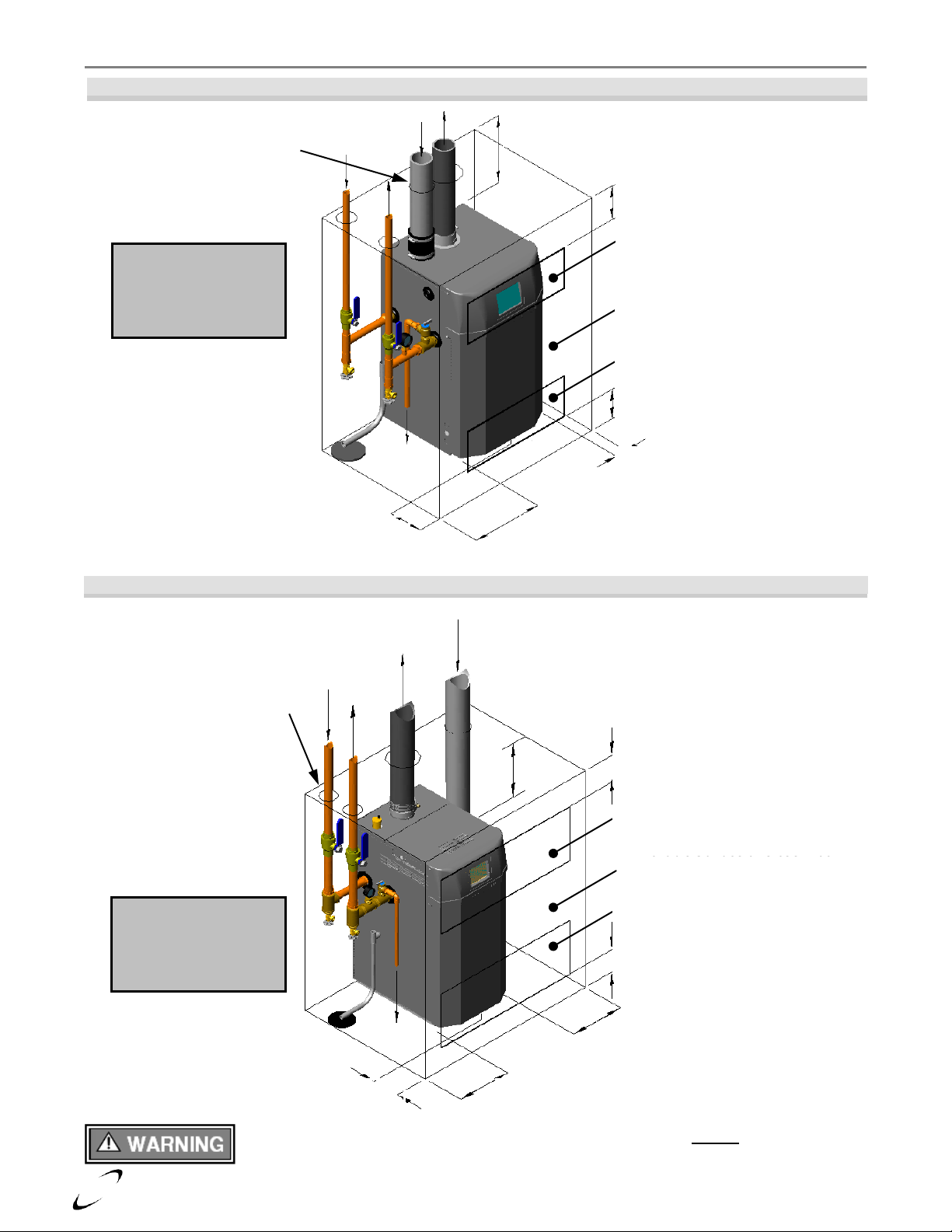
Floor Mounting
The Trinity Lx can be mounted directly on combustible flooring, with the exception of carpeting. Installing the
water heater on carpeting is not permissible. Ensure the water heater is mounted above any anticipated flood
level. Models Lx200WH-Lx400WH come equipped with stationary, low profile legs. Models Lx500WH-
Lx800WH include factory supplied/field installed leveling legs. Once the unit is removed from the pallet, thread
the leveling legs into the allocated threaded inserts in the bottom of the unit.
Water heater Area Ventilation Air Openings
Direct Vent –If water heater area clearances are less than the recommended clearances specified in Table 3-1,
the water heater area must be ventilated. (Exception: if the water heater area/room has a volume of 150 ft3or
greater, ventilation of the water heater room is not required). Each ventilation air opening must meet the
minimum requirements of 1 in2per 1000 Btu/hr, but not less than 100 in2. The lower ventilation opening
must be located within 6” of the floor while the upper opening must be located 6” from the top of the space.
If the "Water heater Area" does not meet the recommended clearances listed in Table 3-
1, and if the water heater area has a volume less than 150 ft3, it is considered a Closet or
Alcove. PVC vent pipe and fittings shall not be used within the closet or alcove; only
approved CPVC, Polypropylene or Stainless Steel vent pipe and fittings can be used.
See Table 4-3 for a list of approved materials.
Indoor Combustion Air –When using Indoor Combustion Air in lieu of Direct Vent air-inlet piping (an option
for models Lx500WH-Lx800WH), provisions for combustion and ventilation air, in accordance with section
“Air for Combustion and Ventilation,” of the National Fuel Gas Code, ANSI Z223.1/NFPA 54 (U.S.), or
Clause 8.2, 8.3 or 8.4 of Natural Gas and Propane Installation Code, CAN/CSA B149.1 (Canada), or
applicable provisions of the local building codes, must be adhered to.
Closet Installations
For closet installations, it is necessary to provide two ventilation air openings as shown in Figure 3-1(a), (b) and
(c), each providing a minimum area equal to 1 in2per 1000 Btu/hr, but not less than 100 in2and within 6” of the
top and bottom of the closet door. See Table 3-1for minimum recommended clearances.
Alcove Installations
Alcove installations have the same minimum clearances as closet installations, except the front must be
completely open to the room at a distance no greater than 18” [457 mm] from the front of the water heater and
the room is at least three (3) times the size of the alcove. Provided these conditions are met, the water heater
requires no extra ventilation air openings to the space. See Table 3-1for minimum recommended clearances.
Residential Garage Installations
When installed in a residential garage, mount the water heater a minimum of 18” [457 mm] above the floor.
Locate or protect the water heater so it cannot be damaged by a moving vehicle. Check with your local
authorities for other possible regulations pertaining to the installation of a water heater in a garage.
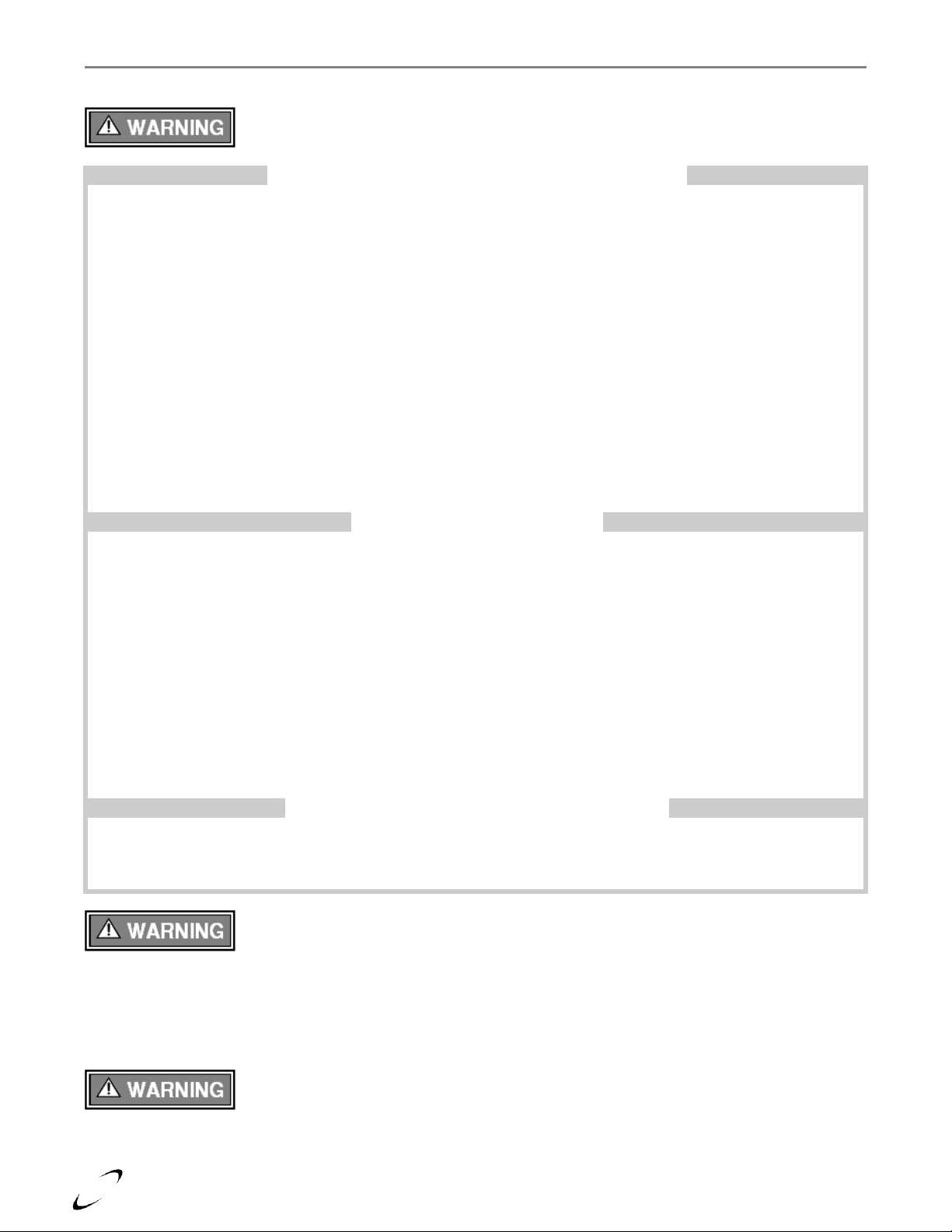
Wall Mounting Installations (Optional)
Lx200WH-Lx400WH models are shipped with wall mounting brackets to provide installers with the option of
wall mounting the water heater. Lx500WH-Lx800WH models are not available as a wall mountable unit. Refer
to Figures 3-3(a) and 3-3(b) for instructions and illustrations on wall mounting applicable models.

Trinity Lx │Installation and Operation Instructions Lx –WH Series
8
Figure 3-1(a) Closet Installation, Minimum Clearances (Lx200WH)
Figure 3-1(b) Closet Installation, Minimum Clearances (Lx300WH & Lx400WH)
Closet/alcove installations in US and Canada require approved CPVC vent and air-inlet
pipe, fittings, cements and primers (Table 4-3).
Ventilation Air Openings
are not required if the
appliance area meets
the listed Recommended
Clearances in Table 3-1.
Top 12” [305 mm]
Removable Surface or Closet Door
Ventilation Air Opening
1 in2per 1000 Btu/hr, min. 100 in2
Ventilation Air Opening
1 in2per 1000 Btu/hr, min. 100 in2
6” [152 mm] max. above vent opening
6” [152 mm] max. below vent opening
Right Side 4” [102 mm]
Left Side 12” [305 mm]
Front 6” [152 mm]
Piping must be CPVC
1” [25 mm] clearance for
hot water and vent pipes
Removable Surface or Closet Door
Ventilation Air Openings
are not required if the
appliance area meets
the listed Recommended
Clearances in Table 3-1.
Top 12” [305 mm]
6” [152 mm] max. above vent opening
Front 6” [152 mm]
Left Side 12” [305 mm]
Right Side 12” [305 mm]
6” [152 mm] max. below vent opening
Ventilation Air Opening
1 in2per 1000 Btu/hr, min. 100 in2
Ventilation Air Opening
1 in2per 1000 Btu/hr, min. 100 in2
Piping must be CPVC
1” [25 mm] clearance for
hot water and vent pipes

Lx –WH Series Installation and Operation Instructions │Trinity Lx
9
Figure 3-1(c) Closet Installation, Minimum Clearances (Lx500WH-Lx800WH)
Table 3-1 Minimum Clearances for Installation and Service
Model No.
Clearances
Dimensions - inches
Front
Top
Left Side
Right Side
Rear
Flue Pipe
Lx200WH
Minimum
361
12
12
4
04
1
Recommended
36
24
242
4
04
1
Lx300WH & Lx400WH
Minimum
361
12
12
12
04
1
Recommended
36
24
242
12
04
1
Lx500WH-Lx800WH3
Minimum
361
12
24
4
14
1
Recommended
36
24
30
24
18
1
Notes:
1 6” if surface is removable allowing 36”clearance (i.e. closet installation). See Ventilation Air Opening dimensions in
Figure 3-1.
2 Clearances can be as low as 12” if the right side has a clearance of 24”.
3 For models Lx500WH-Lx800WH, ensure rear of unit is accessible for wiring and flue gas testing.
4 Code requires all wall mounted instantaneous water heaters to be installed with suitable wall protection extending the full
length and width of the water heater. Check with local authorities regarding acceptable protection materials.
Piping
must be
CPVC
Front 24” [610 mm]
Left Side 24”
[610 mm]
Right Side
4” [102 mm]
6” [152 mm]
max. below
vent opening
Top 12”
[305 mm]
1” [25 mm]
clearance for
hot water and
vent pipes
6” [152 mm]
max. above
vent opening
Removable Surface
or Closet Door
Ventilation Air Opening
1 in2per 1000 Btu/hr,
min. 100 in2
Ventilation Air Opening
1 in2per 1000 Btu/hr,
min. 100 in2
Ventilation Air Openings -
Openings are not required if
the appliance area meets the
Recommended Clearances in
Table 3-1.
Rear 14”
[356 mm]
Access - Ensure rear of unit is
accessible for wiring and flue
gas testing. See Table 3-1.
Model Lx800
shown

Trinity Lx │Installation and Operation Instructions Lx –WH Series
10
Figure 3-2(a) Wall Mounting Installations (Lx200WH)
Remove the upper wall mount bracket from the
back of the water heater.
Failure to follow instructions may
result in fire, serious injury, or death.
Secure the upper wall mount bracket to a solid
wall using field supplied lag screws (anchors
when mounting on a concrete wall) that are
adequate to support the weight of the water
heater. Ensure the bracket is mounted in the
level position. Refer to Table 2-1
Specifications for water heater weight.
This unit requires two people to lift it
or damage and injury may result.
Mount the water heater to the bracket by
aligning the slots in the back of the water
heater with the hooks protruding from the wall
bracket. The top of the slots must rest at the
bottom of the groove in the hooks of the wall
mount bracket.
Pull the bottom of the unit away from the wall
to allow the installation of the lower wall
mount bracket (included with water heater).
The bracket will snap into place using the slots
provided in the bottom of the unit (ensure the
snaps lock into place, once installed the bracket
should not be easily removed).
Code requires all wall mounted instantaneous water heaters to be installed with suitable
wall protection extending the full length and width of the water heater. Check with local
authorities regarding acceptable protection materials.
1” Clearance for Vent and
Hot Water Piping.
Ensure that the top of each
slot rests on the bottom of the
grooves in the wall bracket.
Bottom Bracket is in
Lx Installation Kit Box

Lx –WH Series Installation and Operation Instructions │Trinity Lx
11
Figure 3-2(b) Wall Mounting Installations (Lx300WH-Lx400WH)
While leaving the upper bracket intact (A),
remove the wall mount bracket attached to the
Failure to follow instructions may
result in fire, serious injury, or death.
bottom-back of the boiler (B). Save the
mounting hardware for Step 4.
Secure the wall mount bracket, removed from
the bottom of the boiler in Step 1, to a solid
wall using field supplied lag screws (anchors
when mounting to a concrete wall) that are
adequate to support the weight of the boiler
(refer to Table 2-1 Specifications). Ensure the
wall mount bracket is mounted level and flush
to the wall with mounting holes on the bottom,
flange pointed upward and angled away from
the wall.
This unit requires two people to lift it
or damage and injury may result.
Mount the boiler to the wall by aligning the
upper bracket (A) with the wall mount bracket
(B). Slide the upper bracket down over the
wall mount bracket until it hooks.
Once the boiler is resting securely on the upper
bracket, secure the bottom bracket to the
underside of the boiler using the mounting
hardware removed in Step 1; then, anchor the
bottom bracket to the wall as shown.
Code requires all wall mounted instantaneous water heaters to be installed with suitable
wall protection extending the full length and width of the water heater. Check with local
authorities regarding acceptable protection materials.
B
A
Ensure that the
upper bracket
on the back of
the appliance
(A) slides down
over the wall
mount bracket
(B) and rests
securely on it.
A
B
Bottom Bracket is in
Lx Installation Kit Box
B

Trinity Lx │Installation and Operation Instructions Lx –WH Series
12
4.0 GENERAL VENTING
The Trinity Lx is certified as a “Category IV” water heater requiring a “Special Venting System” designed for
pressurized venting. The Exhaust Vent must be piped to the outdoors, using the vent materials and rules outlined
in this section. Under no conditions may this unit vent gases into a masonry chimney, unless it is vacant, and
utilizes the approved venting material and rules described in this section.
Vent and Air-inlet are to be piped separately. The Trinity Lx cannot share a common vent
or air-inlet with multiple appliances. Failure to comply will result in serious injury or
death.
Removing an Existing Water heater from Common Venting System
Do not install the Trinity Lx into a common venting system with any other appliances.
Failure to comply with this warning will cause flue gas spillage and leech carbon
monoxide emissions into the surrounding air resulting in serious injury or death.
When an existing water heater is removed from a common venting system, the common
venting system is likely to be too large for proper venting of the remaining appliances
connected to it. Instructions have been provided on how to remove the existing water
heater and how to resize the remaining venting system. Failure to follow these
instructions may result in property damage, serious injury or death.
At the time of removal of an existing water heater, the following steps shall be followed with each appliance
remaining connected to the common venting system placed in operation, while the other appliances remaining
connected to the common venting system are not in operation.
Steps to Removing an Existing Water Heater
1. Seal any unused openings in the common venting system.
2. Visually inspect the venting system for proper size and horizontal pitch. Verify that there is no blockage,
restriction, leakage, corrosion or other deficiencies which could cause an unsafe condition.
3. Insofar as is practical, close fireplace dampers, all building doors and windows and all doors between the
space in which the appliances remaining connected to the common venting system are located and other
spaces of the building. Turn on clothes dryers and any appliance not connected to the common venting
system. Turn on any exhaust fans, such as range hoods and bathroom exhausts, so they will operate at
maximum speed. Do not operate a summer exhaust fan.
4. Place in operation the water heater being inspected. Follow the lighting instructions. Adjust thermostat so
water heater will operate continuously.
5. Test for spillage at the draft hood relief opening after 5 minutes of main burner operation. Use the flame of a
match or candle, or smoke from a cigarette, cigar or pipe.
6. After it has been determined that each appliance remaining connected to the common venting system
properly vents when tested as outlined above, return doors, windows, exhaust fans, fireplace dampers and
any other gas burning appliance to their previous condition of use.
7. Any improper operation of the common venting system should be corrected so the installation conforms with
the National Fuel Gas Code, ANSI Z223.1/NFPA 54 and/or CAN/CSA B149.1, Natural Gas and Propane
Installation Code. When resizing any portion of the common venting system, the common venting system
should be resized to approach the minimum size as determined using the appropriate tables in Part 11 of the
National Fuel Gas Code, ANSI Z223.1/NFPA 54 and/or CAN/CSA B149.1, Natural Gas and Propane
Installation Code.

Lx –WH Series Installation and Operation Instructions │Trinity Lx
13
Direct Vent Installation (Mandatory for models Lx200WH-Lx400WH)
When installed as a Direct Vent water heater the combustion air-inlet must also be piped directly to the outdoors
using the methods described in this section and in accordance with the National Fuel Gas Code, ANSI Z223.1
(U.S.) or CSA B149.1 (Canada) and local requirements.
Indoor Combustion Air (Optional for models Lx500WH-Lx800WH)
When the installation uses Indoor Combustion Air (i.e. piping is not directly connecting the water heater air-inlet
fitting to the outdoors), provisions for combustion and ventilation air, in accordance with section “Air for
Combustion and Ventilation,” of the National Fuel Gas Code, ANSI Z223.1/NFPA 54 (U.S.), or Clause 8.2, 8.3
or 8.4 of Natural Gas and Propane Installation Code, CAN/CSA B149.1 (Canada), or applicable provisions of
the local building codes, must be adhered to.
The water heater shall be located so as not to interfere with proper circulation of
combustion, ventilation, and dilution air.
Make up air requirements for the operation of exhaust fans, kitchen ventilation systems,
clothes dryers, and fireplaces shall be considered in determining the adequacy of a space
to provide combustion air requirements. Failure to ensure adequate make up air to all
appliances may result in personal injury or death.
Controller RPM Adjustments –To avoid the potential water heater lockouts due to wind
and static pressure differences, the Lightoff and Minimum Modulation RPM Rates must be
adjusted as per Figures 4-11 and 4-21 in Appendix A when using indoor combustion air.
Air Filter Kit (P/N 84093) –When using indoor combustion air (non-Direct Vent), it is highly recommended to
use the optional Air Filter Kit (P/N 84093) to limit the amount of dust that enters the combustion system. The
Filter Kit can be installed on water heater models Lx500WH-Lx800WH, as illustrated in Figure 4-1
(comprehensive installation instructions are provided with the Filter Kit).
Venting Limitation –When using the Air Filter Kit on models Lx500WH & Lx600WH,
the maximum equivalent exhaust vent length is limited to 30 ft. with 4” piping, or 90 ft.
with 6” piping; see warning below Table 4-5.
Figure 4-1 Installation of Optional Air Filter Kit (P/N 84093)
Remove factory appliance
air-inlet adapter; keep screws
from installation of filter kit
Secure filter kit using factory
screws removed in step 1.
Reuse the factory gasket.
Secure the filter in place
with the brackets and knurled
screws provided in the filter kit.

Trinity Lx │Installation and Operation Instructions Lx –WH Series
14
Combustion Air-inlet Contamination
Be careful not to locate the Air-inlet termination in an area where contaminants can be drawn in and used for
combustion. Combustion air containing dust, debris or air-borne contaminants will drastically increase the
required maintenance and may cause a corrosive reaction in the Heat Exchanger which could result in premature
failure, fire, serious injury, or death. See Table 4-1 for a list of areas to avoid when terminating air-intake piping:
Table 4-1 Corrosive Products and Contaminant Sources
Products to Avoid
Contaminated Sources to Avoid
Antistatic fabric softeners, bleaches, detergents, cleaners
Laundry facilities
Perchloroethylene (PCE), hydrocarbon based cleaners
Dry cleaning facilities
Chemical fertilizer, herbicides/pesticides, dust, methane gas
Farms or areas with livestock and manure
Paint or varnish removers, cements or glues, sawdust
Wood working or furniture refinishing shops
Water chlorination chemicals (chloride, fluoride)
Swimming pools, hot tubs
Solvents, cutting oils, fiberglass, cleaning solvents
Auto body or metal working shops
Refrigerant charge with CFC or HCFC
Refrigerant repair shops
Permanent wave solutions
Beauty shops
Fixer, hydrochloric acid (muriatic acid), bromide, iodine
Photo labs, chemical / plastics processing plants
Cement powder, crack fill dust, cellulose, fiber based insulation
Concrete plant or construction site
Do not store or use gasoline or other flammable vapors and liquids in the vicinity of this
or any other appliance. Failure to follow instructions may result in serious injury or death.
It is BEST PRACTICE to pipe the combustion air-inlet directly to the outdoors (Direct
Vent installation) to avoid contamination often contained in indoor air.
Flammable Solvents and Plastic Piping
Due to the extremely flammable characteristics of most glues, cements, solvents and primers used in the process
of joining plastic vent and air-inlet pipe, explosive solvent vapors must be evacuated from the vent and air-intake
prior to start-up. Avoid using excess cement or primer that may lead to pooling inside the pipe assembly. Freshly
assembled piping assembly should be allowed to cure for a minimum of 8 hours before applying power to the gas
fired appliance. Refer to Mandatory Pre-commissioning Procedure for Plastic Venting in this section.
Flammable Cements and Primers –It is the installers’ responsibility to familiarize
themselves with the hazards associated with explosive solvents and to take all precautions
to reduce these risks. Failure to follow these instructions can cause explosions, property
damage, injury or death.
Mandatory Pre-commissioning Procedure for Plastic Venting (PVC or CPVC)
Do not apply power to the water heater prior to Step 4 in the Mandatory Pre-
commissioning Procedure for Plastic Venting.
Spark Igniter Cable -Maintain a minimum 2” separation between spark igniter circuit
and conductors. Failure to follow instructions may result in component failure, injury or
death.
1) Working with the power turned off to the water heater, completely install the vent and air-inlet system,
securely cementing joints together. If possible, allow primers/cements to cure for 8 hours before firing the
burner. If curing time is less than 8 hours, proceed with Steps 2 through 6.
2) Maintain the water heater gas supply shut-off valve in the off position.
3) Disconnect electrical leads to the Hot Surface or Spark Igniter. Ensure the cables are placed in a fashion
where they will not arc to ground or other conductor. Refer to warning regarding Spark Igniter Cable.
4) Turn power on to the water heater and apply a heat demand.
5) Allow for 3 complete trials for ignition, consisting of pre and post purge of the combustion blower, until an
ignition lockout occurs. Repeat the process two more times (i.e. 9 complete ignition sequences in total).
6) Turn power off and reconnect the electrical leads to the Igniter.

Lx –WH Series Installation and Operation Instructions │Trinity Lx
15
Near Water Heater Vent/Air-inlet Piping
Each Trinity Lx is equipped with a short piece of approved CPVC vent pipe (see Table 4-2 CPVC Vent Pipe
Transition Piece). Insert one end into the water heater flue outlet adapter and cement the other to field venting
(see Table 4-4 for approved venting material). The CPVC vent pipe should extend fully into the water heater
flue outlet adapter (see Table 4-2). Ensure that the venting system does not apply a load or strain on the water
heater flue outlet adapter. The manufacturer recommends using two elbows to create a “swing joint”to reduce
potential strain on vent piping and cemented joints; see Figures 4-2 through 4-5.
Gasket Seating - Improper seating can cause leakage and eventual failure of the sealing
gasket. Failure to follow these instructions may result in serious injury or death.
PVC Exhaust Venting –DO NOT insert PVC pipe directly into the water heater exhaust
adapter, as it can deform from the clamping force of the gear clamp. Failure to follow
these instructions may result in gasket failure and/or the dislodging of the exhaust pipe
from the water heater adapter, resulting in property damage, serious injury or death.
Table 4-2 CPVC Vent Pipe Transition Piece (used when venting with PVC)
Model No.
CPVC Vent Pipe Size
CPVC Transition Vent Pipe Length
Full Insertion Depth
Lx200WH
3”
Minimum 5” [127 mm]
2-7/8” [73 mm]
Lx300WH-Lx600WH
4”
Minimum 4” [100 mm]
1-7/8” [48 mm]
Lx700WH & Lx800WH
6”
Minimum 6” [152 mm]
2-1/2” [63 mm]
Polypropylene or Stainless Steel Venting –When using Polypropylene or Stainless Steel
piping, the appropriate water heater adapters must be used to transition the water heater
vent connections to accept the respective Polypropylene or Stainless Steel venting. See
Table 4-3 for a list of approved adapters. Failure to use the correct adapter will result in
flue gas leakage resulting in property damage, serious injury or death.
Table 4-3 Water heater Adapters for Polypropylene and Stainless Steel Venting
Model No.
Vent Material
Venting Brand
Adapter Part No. 1,2
Lx200WH
Polypropylene
DuraVent –PolyPro
300150
Centrotherm - InnoFlue
ISANY0303
Stainless Steel
DuraVent –FasNSeal
300715
Lx300WH-Lx600WH
Polypropylene
DuraVent –PolyPro
300151
Centrotherm - InnoFlue
ISAA0404
Stainless Steel
DuraVent –FasNSeal
303631
Lx700WH & Lx800WH
Polypropylene
DuraVent –PolyPro
810004281
Centrotherm - InnoFlue
ISAA0606
Stainless Steel
DuraVent –FasNSeal
810005231
Notes:
1 Listed water heater adapters are only approved for use with the respective venting brand; i.e. a PolyPro water heater
adapter shall not be used with InnoFlue venting.
2 PolyPro and FasNSeal water heater adapters are available from DuraVent (1-800-835-4429 or www.duravent.com);
InnoFlue water heater adapters are available from Centrotherm Eco Systems (1-877-434-3432 or
www.centrotherm.us.com).
Exhaust venting must be supported to reduce strain on piping joints. Failure to
follow these instructions may result in result in damage, serious injury or death.
In Canada, the first 3 ft(915 mm) of vent piping must be readily accessible for inspection.

Trinity Lx │Installation and Operation Instructions Lx –WH Series
16
Figure 4-2(a) Near Water Heater Venting (CPVC)
Figure 4-2(b) Near Water Heater Venting (PVC)
Model Lx200WH
Model Lx200WH
Figure 4-3(a) Near Water Heater Venting (CPVC)
Figure 4-3(b) Near Water Heater Venting (PVC)
Models Lx300WH & Lx400WH
Air-Inlet - check with applicable local codes for acceptable pipe material.
Flue Outlet
Stainless Steel Adapter
(factory supplied)
Exhaust Vent
3” CPVC
Swing Joint
to attain slope in
horizontal runs
Air Inlet
3” Pipe *
Coupling
3” Removable
(field supplied)
Air Inlet
3” Pipe *
Coupling
3” Removable
(field supplied)
Swing Joint
to attain slope in
horizontal runs
Exhaust Vent - 3” PVC,
(check local codes and
Table 4-3)
Coupling 3” PVC
Flue Outlet
Stainless Steel
Adapter (factory
supplied)
INLESS
THE VENT /AIR-
INLET
PIPES ARE
FIELD
SUPPLIED.
MAJOR
COMPONE
NTS
PROVIDED
IN SIDE-
WALL
TERMINA
TION KIT
INCLUDE
VENT
SCREEN,
INTERIOR
TRIM,
AND VENT
TERMINA
L.
teel Adapter
(factory supplied)
Transition Piece
3” CPVC, minimum 5”
long (factory supplied)
Mandatory Vent Pipe
Transition Piece
See Table 4-2.
Air-Inlet
4” Pipe *
Swing Joint
to attain slope in
horizontal runs
Exhaust Vent
4”/6” CPVC
Flue Outlet
Stainless Steel Adapter
(factory supplied)
Coupling
4” Removable
(factory supplied)
supplied)
90oelbow typical, or tee and
drain cap option for easy cleanouts
Air-Inlet
4” Pipe *
Swing Joint
to attain slope in
horizontal runs
Coupling
4”/6”x4” PVC
Flue Outlet
Stainless Steel Adapter
(factory supplied)
Coupling
4” Removable
(factory supplied)
supplied)
Exhaust Vent
4”/6” PVC (check local
codes and Table 4-3)
Transition Piece
4” CPVC, minimum 4”
long (factory supplied)
90oelbow typical, or tee and
drain cap option for easy cleanouts
Mandatory Vent Pipe
Transition Piece
See Table 4-2.

Lx –WH Series Installation and Operation Instructions │Trinity Lx
17
Figure 4-4(a) Near Water Heater Venting (CPVC/PVC)
Models Lx500WH & Lx600WH
Figure 4-5(a) Near Water Heater Venting (CPVC)
Figure 4-5(b) Near Water Heater Venting (PVC)
Models Lx700WH & Lx800WH
Air-Inlet - check with applicable local codes for acceptable pipe material.
Air-Inlet 4” Pipe *
Exhaust Vent
6” CPVC
Swing Joint
to attain slope in
horizontal runs
Flue Outlet 6”
stainless steel
elbow (factory
supplied)
Air-Inlet Adapter
4” stainless steel
(factory supplied)
90oelbow typical, or tee
and drain cap option for
easy cleanouts
Air-Inlet Adapter
4” stainless steel
(factory supplied)
90oelbow typical, or tee
and drain cap option for
easy cleanouts
Flue Outlet 6”
stainless steel
elbow (factory
supplied)
Exhaust Vent
6” PVC (check
local codes
and Table 4-3)
Coupling 6”
PVC, length 4”
Air-Inlet 4/6” Pipe *
Transition
6” CPVC
Swing Joint
to attain slope in
horizontal runs
Mandatory Vent Pipe Transition Piece
6” CPVC (factory supplied). See Table 4-2.
Air-Inlet
4” Pipe *
Exhaust Vent
4” CPVC
Swing Joint
to attain slope in
horizontal runs
Flue Outlet 4”
stainless steel
(factory supplied)
Air-Inlet Adapter
4” stainless steel
(factory supplied)
90oelbow typical, or tee
and drain cap option for
easy cleanouts
Exhaust Vent
4” PVC (check
local codes
and Table 4-3)
Mandatory Vent Pipe
Transition Piece
4” CPVC (factory supplied).
See Table 4-2.
Transition
4” CPVC
OR

Trinity Lx │Installation and Operation Instructions Lx –WH Series
18
Vent/Air-inlet Pipe Material
Table 4-4 Acceptable Vent and Air-inlet Pipe Material
Items 1
Materials 2, 3
Installation Standards
All Vent and Air-inlet
materials installed on gas
fired appliances in CAN/US
must meet the Standards
listed in Table 4-4. Failure
to comply could result in
fire, serious injury or death.
United States
Canada 4
Vent Piping
and Fittings
PVC - DWV
ANSI/ASTM D2265
All venting material in
Canada must be
ULC S636 approved.
See Note 4 below for
appropriate temperature
applications.
PVC Schedule 40
ANSI/ASTM D1785
CPVC Schedule 40
ANSI/ASTM F441
AL29-4C
UL-1738
Polypropylene (PP)
-
Pipe Cement
PVC
ANSI/ASTM D2564
CPVC
ANSI/ASTM F493
Primers
PVC / CPVC
ANSI/ASTM F656
Notes:
1 Refer to Table 4-5 for Allowable Vent and Air-inlet Pipe Sizes and Lengths.
2 PVC venting (exhaust and air-intake) is not permitted within the Closet/alcove of a Closet/alcove installation.
3 The Air-Intake does not require high temperature pipe material. Check applicable local codes for acceptable materials.
4 ULC S636 PVC is approved for flue gas temperatures up to 149oF (65oC) and must only be used for low temperature
applications. High temperature applications requiring water heater supply water temperatures greater than 140oF
(60oC) must use ULC S636 CPVC, PP or AL29-4C.
The use of cellular core PVC (ASTM F891), cellular core CPVC, or Radel®
(polyphenolsulfone) in the exhaust venting system is prohibited. Failure to follow these
instructions may result in property damage, personal injury or death.
Covering non-metallic vent pipe and fittings with thermal insulation is prohibited. Failure
to follow these instructions may result in property damage, personal injury or death.

Lx –WH Series Installation and Operation Instructions │Trinity Lx
19
Vent and Air-inlet Pipe Length Determination
Use Table 4-5 to determine the maximum pipe length that can be used. The table calculates sweep, 90º elbows,
and 45º elbows at 5 equivalent feet each. Note: model Lx200WH has limitations when operating with Propane
Gas (LP).
Example:An Lx200WH can be installed with 105 equivalent feet of air-inlet piping and 105 equivalent feet of
exhaust vent piping when operating with Natural Gas. When operating with Propane Gas (LP), the maximum
length of each the exhaust vent and air-inlet pipe is limited to 50 equivalent feet (3” diameter pipe).
The length of one vent pipe (air-inlet or exhaust) may not exceed the length of the other
vent pipe by more than 20 equivalent feet.
Table 4-5 Allowable Vent and Air-Intake Pipe Size and Lengths
Model
Pipe Size
Gas
Length
ft.
Number of Elbows (90’s or 45’s) and Equivalent Feet
1
2
3
4
5
6
7
8
9
Lx200WH
3”
LP
50
45
40
35
30
25
20
15
10
5
3”
NG
105
100
95
90
85
80
75
70
65
60
4”
NG
& LP
105
100
95
90
85
80
75
70
65
60
Lx300WH &
Lx400WH
4” or 6”
NG
& LP
100
95
90
85
80
75
70
65
60
55
Lx500WH
4” or 6” 3
NG & LP
100
95
90
85
80
75
70
65
60
55
Lx600WH
4”or 6” 3
NG2
100
95
90
85
80
75
70
65
60
55
Lx700WH &
Lx800WH
6” 1
NG2
100
95
90
85
80
75
70
65
60
55
Notes:
1Only 6” exhaust vent is permissible for models Lx700-800. Air-inlet pipe can be 4” or 6” (6” is highly recommended).
2Models Lx600WH-Lx800WH operate with Natural Gas only.
3Models Lx500WH & Lx600WH are limited to 30 ft. of 4” or 90 ft. of 6” exhaust venting when using the Air Filter Kit
(P/N 84093).
Air Filter Kit venting restrictions - Models Lx500WH & Lx600WH are limited to 30
equivalent feet of 4” (or 90 equivalent feet of 6”) exhaust vent when using the optional
Air Filter Kit. When transitioning from 4” to 6”, the 4” venting used must be counted 3
times to convert to an equivalent length in 6”.
Example: An application uses one 90º elbow and 5 feet of 4” venting before converting to 6”; therefore, the 4”
venting has an equivalent length of 30’ [(5’+5’) x 3] of 6” venting; thus allowing an additional 60’ equivalent
of 6” venting (Note: Example is only true with Lx500-600 models using the optional Indoor Combustion Air
Kit).

Trinity Lx │Installation and Operation Instructions Lx –WH Series
20
Termination Options –Direct Vent Installation
The venting system of the Trinity Lx may be terminated using field supplied piping to construct a “Two-Pipe”
termination, see Figures 4-6(b), 4-7(a), 4-7(b) and 4-8(a); alternatively the venting may be terminated using a
factory kit selected from Table 4-6.
Kits certified with the Trinity Lx are listed in Table 4-6 and available from IPEX, DuraVent, Centrotherm and/or
NTI. For more information on System 636 Vent Kits or wholesaler locations contact IPEX directly USA: 1-800-
463-9572 or www.IPEXamerica.com │CAN: 1-866-473-9462 or www.ipexinc.com. For more information on
PolyPro Vent Kits or wholesaler locations contact DuraVent directly 1-800-835-4429 or www.duravent.com. For
more information on InnoFlue Vent Kits or wholesaler locations contact Centrotherm directly at 1-877-434-3432
or www.centrotherm.us.com.
Table 4-6 Optional Vent Termination Kits
Description
Vent
Size
Supplier P/N
Figure
Vent Material
Compatibility
Vent Option
Roof
Wall
IPEX Low Profile
(Flush Mount)7
3”
196985 (NTI P/N 84357)
4-9
PVC/CPVC7
4”
196986 (NTI P/N 84358)
IPEX Concentric
(Wall/Roof)5,6,7,8
3”
196116 (NTI P/N 82666)
4-9(b), 4-10(b)
PVC/CPVC7
197117
4”
196021 (NTI P/N 84355)
197021
DuraVent - PolyPro
Concentric (Wall)
3”
3PPS-HK
4-9(d)
PVC/CPVC/PP
4”
4PPS-HK
DuraVent - PolyPro
Concentric (Roof)
3”
3PPS-VK
4-10(c)
PVC/CPVC/PP
4”
4PPS-VK
Centrotherm –InnoFlue
(Flush Mount)
3”
ISLPT0303
4-9
PVC/CPVC/PP
Centrotherm –InnoFlue
Concentric (Wall)9
3”
ICWS3513 & ICTC0335
4-9(d)
PVC/CPVC/PP
ICWT352 & ICTC0335
4”
ICWS4639 & ICTC0446
Centrotherm –InnoFlue
Concentric (Roof)9
3”
ICRT3539 & ICTC0335
4-10(c)
PVC/CPVC/PP
4”
ICRT4679 & ICTC0446
Notes:
1Instructions included with termination kits contain detailed assembly and installation instructions.
2All factory termination kits are ULC S636 approved.
3Clearance requirements in this manual supersede those of the instructions included with the vent terminal.
4Piping MUST be secured to the vent terminal during installation.
5IPEX Concentric Terminal MUST be cemented together and to the vent pipes during installation.
6Vent Screens provided with water heater may be used with the IPEX Concentric Vent Kits; otherwise use IPEX vent
screens (3 in. vent screen P/N 196051 –each sold separately).
7IPEX Low Profile and Concentric kits (excluding P/N 197009) are constructed out of ULC S636 approved PVC; check
with your local authority for the acceptance of PVC as a venting material prior to use.
8 IPEX Concentric kits can be shortened to fit the requirements of the installation; see instructions included with the kit
for more details.
9Centrotherm Concentric termination kits must use the applicable “Twin pipe to concentric adapter,”part number
ICTC0335 or ICTC0446.
10 3” Vent Termination Kits may only be used with model Lx200WH.
Models Lx300WH-Lx800WH are not approved for use with any of the 3” vent
termination kits; only 4” vent termination kits, listed in Table 4-6, are acceptable.
PVC In Canada - Authorities in some jurisdictions may not allow the use of any PVC
venting materials with condensing water heaters; check with the local safety inspector to
verify compliance prior to installing a PVC Concentric Vent Kit with a Trinity Lx.
This manual suits for next models
15
Table of contents
Other NTI Water Heater manuals
Popular Water Heater manuals by other brands

Airxcel
Airxcel Suburban IW60 Operation & maintenance guide

Timberk
Timberk SWH RS1 30 V instruction manual

STIEBEL ELTRON
STIEBEL ELTRON PSH 30 EL Operation and installation

OSO HOTWATER
OSO HOTWATER Nano - N SAFETY INFORMATION, O&M INFORMATION, INSTALLATION MANUAL, TECHNICAL DATA SHEET

Takagi
Takagi T-H3J-DV Service handbook

A.O. Smith
A.O. Smith BTN 120 THRU 400/A Series Installation and operaion manual