NTT Advanced Technology FR-1100 User manual

●Do not swing the microphone by pulling the cables of the microphone. Otherwise, the cables may
break and cause accident.
●Do not disassemble or alter the unit.
●Do not drop or give a strong force to the microphone or the unit base while connected.
Doing so may cause damage to the USB terminal or the unit base.
●Dropping this product may cause injury or unit failure. Place the product in a stable location.
Misuse of the product may cause injury to the user or cause property damage.
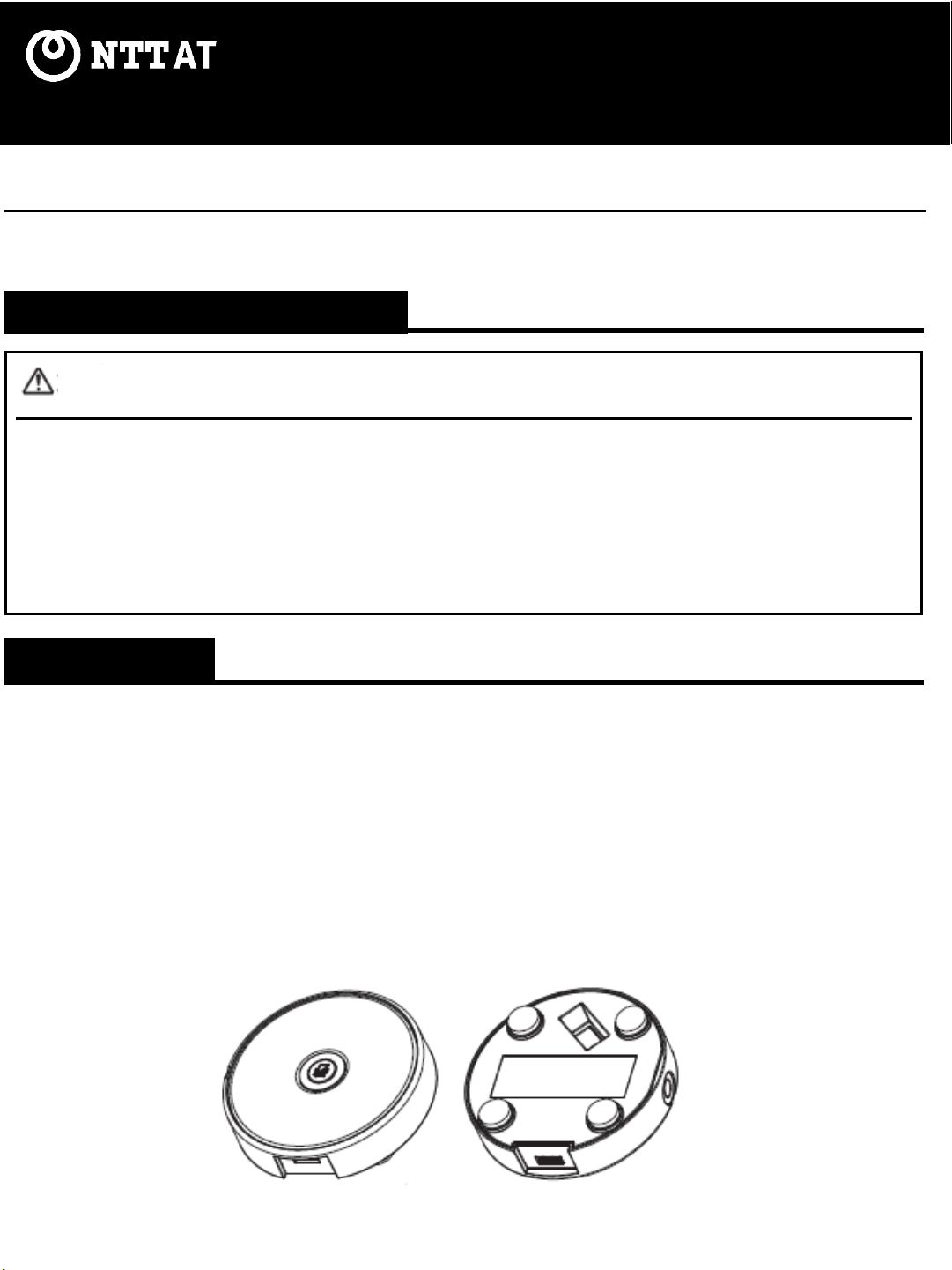
Thank you for purchasing this 2-Directional Boundary Microphone. Please make sure to read this User
Manual beforeuse.
2-Directional Boundary Microphone FR-1100
USER MANUAL
Features
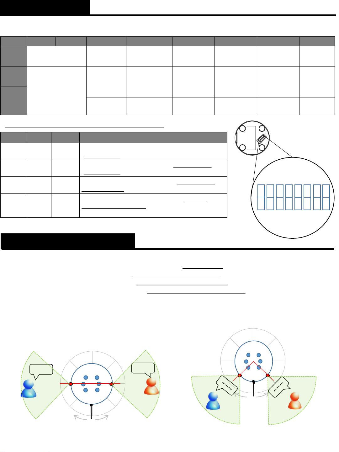
●A compact desktop microphone featuring 2-Directional sound collection, enabled by the
software technology developed by NTT Computer and Data Science Laboratories.
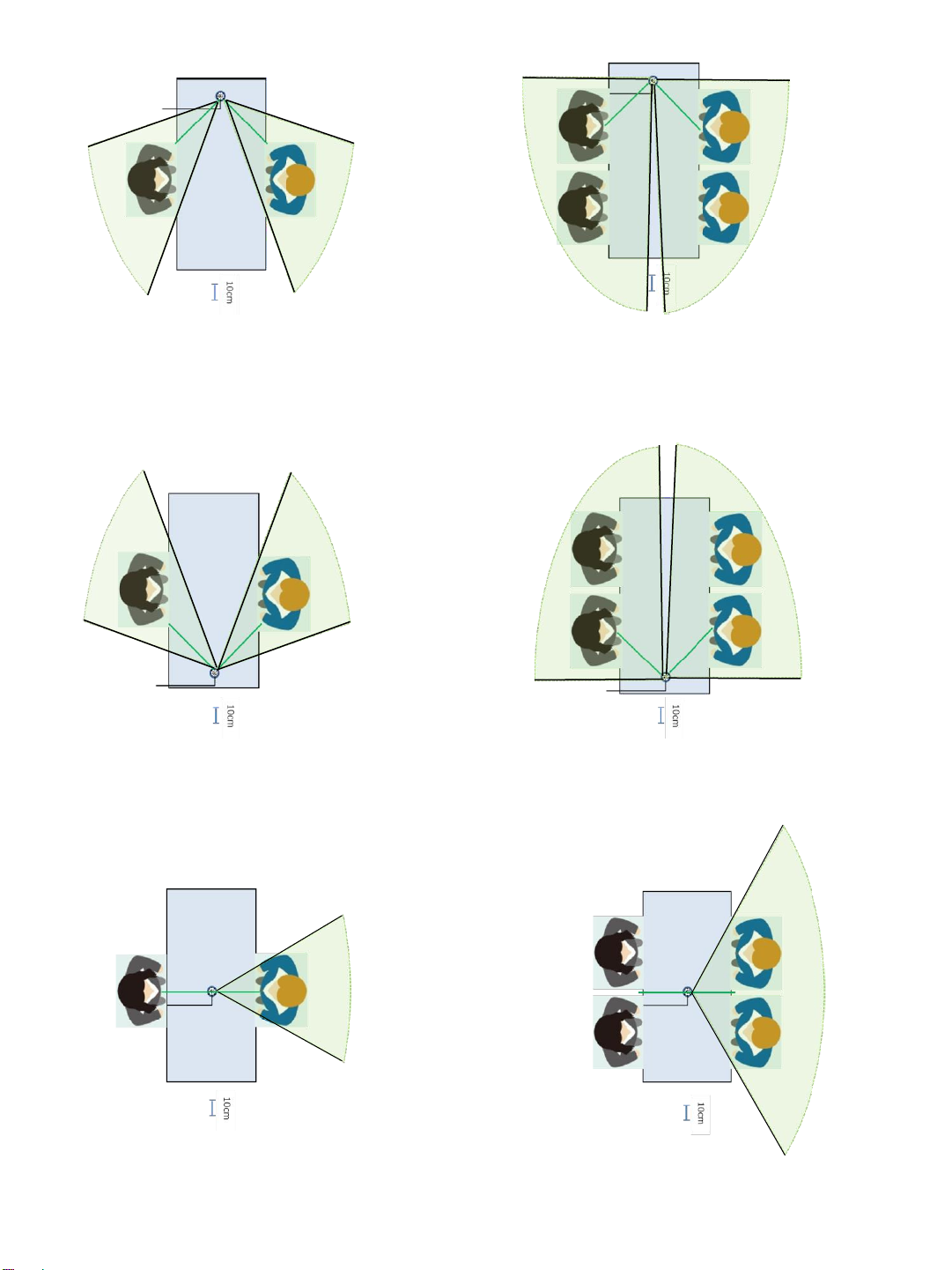
●By switching the directionality, it is possible to collect voice according to various situations.
●High-performance noise-cancelling ability.
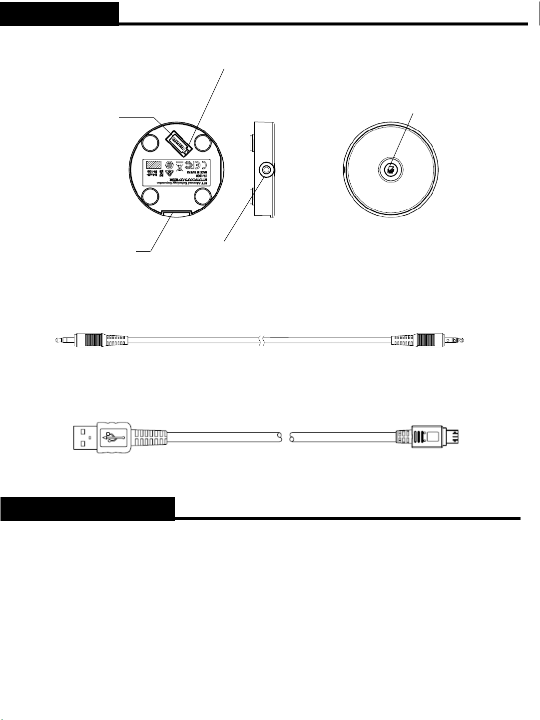
●The collected sound sources can be transmitted to an external device, eg. a recording system,
computer, and tablet*1, via a USB cable or an analog cable (stereo mini plug cable).
*1: This product does not come with any eternal devices. Please refer to the specifications of
each applicable external device.
●As the power is supplied via USB bus power, a personal computer can supply power to the
product as well.
1st Edition Jan. 2023
SAFETY PRECAUTIONS
CAUTION

Part Names
Technical Data
Model: FR-1100
●Directionality Characteristic: 2-directional (stereo)
●Frequency Characteristic:60 to 7,000Hz
●Current Consumption: 100mA
●Power: USB bus power (DC5V)
●External Dimensions: H14.5 mm × φ64.7 mm
●Weight: Approximately 61 g (excluding cables)
●Supported OS: Potentially any OS that supports USB Audio Class 1.0 (tested on Windows 10).
● Accessories: a φ3.5 Stereo Mini Plug cable (approx. 1m) and
a USB (A-micro B) cable (approx. 1 m)
(Specifications may be changed without notice for improvement.)
●Microphone
● φ3.5 Stereo Mini Plug Cable
●USB (A-micro B) Cable
Stereo Jack
For φ3.5 Stereo Mini Plug
DIP Switches
Switch functions
of the product.
micro USB Jack
Mute Button
Whenpressed
and held, blue
LEDs flash,
enabling the mute
function.
Blue LED
Illuminates or flashes
when sound is
detected or settings
are changed.
Red LED (power check)
Flashes when power is supplied.

0°
+45°-45°
-90°
-135°+135°
+90°
0°
+45°-45°
-90°
-135°+135°
+90°
Mode Switching
The DIP switches on the backside of the unit let you set functions and switch between modes.
.1 2 3 4 5 6 7 8
Function
Sets direction.
Sets width of
direction
Sets the blue
LEDs
Sets sound
processing
Sets analog
output Sets USB
output
Sets mute
function
ON
*See table below.
Narrow width
of Directivity
Enabled (LEDs
where sound is
detected
illuminate.)
Enabled Mic output
Loud volume
Enabled
OFF
Broad width
of Directivity
Disabled Disabled Line output
Small volume
Disabled
★Functional Details of DIP Switch Positions 1 and 2
Mode 1 2 Directionality
AON ON
180 degrees: Collects
sound from two directions
(
±90 degrees).
BON OFF
90 degrees: Collects
sound from two directions
(
±45 degrees).
C OFF ON
270 degrees: Collects
sound from two directions
(
±135 degrees).
D OFF OFF
Single direction:Collects sound from
a single
direction (+
90 degrees). (The same content is sent
to both the right and leftchannels.)
1 2 3 4 5 6 7 8
ON
OFF
(A) 180-Degree Mode
Collects sound from
+90 degree direction
Collects sound from
-90 degree direction
~~~
~~~
USB Jack
Collects sound from
+45 degree direction
Collects sound from
-45 degree direction
Directionality may be switched between the following four modes.
(A) 180-degree mode: Collects sound from two directions (±90 degrees).
(B) 90-degree mode: Collects sound from two directions (±45 degrees).
(C) 270-degree mode: Collects sound from two directions (±135 degrees).
(D) Single direction mode: Collects sound from a single direction (+90 degrees). (The same content
is sent to both the right and left channels.)
Setting the Directionality
(B) 90-Degree Mode
USB Jack

0°
+45°-45°
-90°
-135°+135°
+90°
0°
+45°-45°
-90°
-135°+135°
+90°
(C) 270-Degree Mode
USB Jack
(D) Single Direction Mode
Setting the Width of Directivity
(ⅰ)Narrow width of Directivity & 180-
degree Direction (ⅱ)Broad width of Directivity & 180-degree
Direction
The width of the direction can be set and switched between the following eight modes.
(ⅰ)Narrow width of Directivity &180-degreeDirection
(ⅱ)Broad width of Directivity &180-degreeDirection
(ⅲ)Narrow width of Directivity &90-degreeDirection
(ⅳ)Broad width of Directivity &90-degreeDirection
(ⅴ)Narrow width of Directivity &270-degreeDirection
(ⅵ)Broad width of Directivity &270-degreeDirection
(ⅶ)Narrow width of Directivity &Single Direction
(ⅷ)Broad width of Directivity &Single Direction
~~~
USB Jack
Collects sound from
+135 degree direction
Collects sound from
-135 degree direction Collects sound from
+90 degree direction

(ⅲ)Narrow width of Directivity & 90-
degree Direction (ⅳ)Broad width of Directivity & 90-degree
Direction
(ⅴ)Narrow width of Directivity & 270-
degree Direction (ⅵ)Broad width of Directivity & 270-degree
Direction
(ⅶ)Narrow width of Directivity &
Single Direction (ⅷ)Broad width of Directivity & Single
Direction

Setting the Blue LEDs
The following table shows the illumination/flashing patterns of the blue LEDs.
180 Degrees 90 Degrees 270 Degrees Single Direction
Narrow
-width
Broad-
width
Narrow-
width
Broad-
width
Narrow-
width
Broad-
width
Narrow-
width
Broad-
width
When DIP
Switched
1
& 4
flash
quickly
1 & 4
flash
slowly
2 & 3
flash
quickly
2 & 3
flash
slowly
5 & 6
flash
quickly
5 & 6
flash
slowly
1 flashes
quickly
1
flashes
slowly
Normal Off. Or illuminates when sound is detected (for enabled directiononly)
Mute On
All LEDs flash.
Error No. 1, 3, 5, 2, 4, and 6 LEDs flash alternately.
①
②
③
④
⑤⑥
0°
Position
USB Jack
-90 °
φ3.5 Stereo
Mini Jack
Mode Indication
Enabling this setting allows LEDs to illuminate when a sound is detected,and to flash to indicate a
mode change while the DIP is switched.
Whenthe unit detects a sound, the LED located in the direction of the sound source illuminates.
LED illuminates when sound is detected
Setting Analog Output
This setting switches the unit to the analog output mode.
Mic output:Use this to connect to the mic input.
Line output: Use this to connect to the line input.
Setting Sound Processing
This setting switches between enabling and disabling the sound processing function.
Enabled: Directionality and noise cancelling functions are enabled.
Disabled: Directionality and noise cancelling functionsare disabled, and you can use the microphone as a
normal microphone(MONO)to collect sound from all directions.
Setting USB Output
This setting adjusts the volume of USB output.
Choose the appropriate volume that corresponds to the setting of the connecteddevice.
Setting the Mute Function
This setting switches between enabling and disabling the mute function.
Enabled: The mute function is on.
Disabled: The mute function is off.

How to Connect
This product can be connected via a USB cable or a stereo mini plug cable. Check the specificationof the
mic input of the device to which the product is connected.
Using a USB Cable
PC
Note: Read the user manual for the device
to which this product is connected.
USB cable
To a USB input that
supports USB bus power
(1) Place the unit on a horizontalsurface that is not subject to vibration and make sure there is no barrier
between the microphone and the source of voice.
(2) Insert the USB plug into the USB port of the applicable device.
Using a Stereo Cable
PC
Stereo cable
To a stereo mic input.
Note: Plug-in power is not supported.
(1) Place the unit on a horizontalsurface that is not subject to vibration and make sure there is no barrier
between the microphone and the source of voice.
(2) Insert the stereo plug into the mic input / line input of the applicable device.
(3) Connect the USB cable to device that can supply power. Use a power adapter (not
included) to connect to a wall electrical outlet.
USB cable
Note: Read the user manual for the device
to which this product is connected.

Follow the steps below to verify the computersettings. The normal Windows10 screen is used here.
The screen display may differdependingon your operating system.
(1) Click <Start> and then <Settings>.
(2) Click <System>.
(3) Click <Sound>.
(4) Verify that Echo-Cancelling Speakerphone is selected as input device.
Verification of Connection
Verifying Computer Settings (Windows 10)
Note: If the microphone is not recognized, please disconnect the microphone and re-connect it.
Recommended setup position
+30-degree
Range of sound collection in the vertical direction
Elevation angle between speaker’s mouth and FR-1100 is less than
thirty-degree. Make sure that the speaker's mouth remains within the
sound collection range.

e.g. Installation in a straight line
e.g. Diagonal installation.
For installation in a straight line, refer to the diagram below for optimal performances.
For installation in a diagonal line, refer to the diagram below for optimal performances.
Approximately30 cm
between speaker’s mouth
and FR-1100 center
Approximately30 cm
between speaker’s mouth
and FR-1100 center
Approximately30 cm
Approximately30 cm
Approximately 45 cm
between speaker’s mouth
and FR-1100 center
+45-degree
+45-degree
+90-degree
+90-degree
Approximately
30 cm.
Approximately45 cm
between speaker’s mouth
and FR-1100 center

Precautions for Use
●Before use, ensure to read the user manuals for the devices to which this product is connected.
●Weare not responsible whatsoevershould any data in your computer be lost while this product
is connected to it.
●Do not give the product a strong shock.
●Do not expose this product to direct sunlight, or place it near a heating device, or in a hot, humid,
or dusty location. Do not expose this product to water.
●This product may discolor due to friction aftera long period of use.
●To connect/disconnectthe cables, insert/pull it out by inserting/pulling the plug, not the cables.
Otherwise the cables may break and cause accident.
●Do not place any object on the microphone.
●Do not place anything that blocks or reflects the sound within 1 m of the product.
Misuse may result in malfunction.
Caution
Notes on export control
Caution
●Whenre-exporting a product, the customer or end-user must follow the necessary procedures
stipulated in the export-related laws of the country to which the customer or end-consumer belongs.

Should a failure occur while the use is using the product in accordance with the User Manual and clauses
regarding connection and precautions, we will provide a free repair based on the terms and conditions of
the warranty.
Please contact the dealer from whom you purchased this product for questions regarding the product or
consultation regarding a failure and repair.
After-Sales Service
MUZA Kawasaki Central Tower, 1310 Omiya-cho, Saiwai-ku, Kawasaki 212-0014 Japan
Copyright© 2023 NTT Advanced Technology Corporation
NTT Advanced Technology Corporation
Changes or modifications not expressly approved by the party responsible for compliance could
void the user’s authority to operate the equipment.
FCC Caution
This equipment has been tested and found to comply with the limits for a Class B digital device,
pursuant to Part 15 of the FCC Rules. These limits are designed to provide reasonable protection
against harmful interference in a residential installation. This equipment generates, uses and can
radiate radio frequency energy and, if not installed and used in accordance with the instructions,
may cause harmful interference to radio communications. However, there is no guarantee that
interference will not occur in a particular installation. If this equipment does cause harmful
interference to radio or television reception, which can be determined by turning the equipment off
and on, the user is encouraged to try to correct the interference by one or more of the following
measures:
- Reorient or relocate the receiving antenna.
- Increase the separation between the equipment and receiver.
- Connect the equipment into an outlet on a circuit different from that to which the receiver is
connected.
- Consult the dealer or an experienced radio/TV technician for help.
FCC Class B Statement
Supplier's Declaration of Conformity
Certifications
Table of contents
Other NTT Advanced Technology Microphone manuals