NuAire Terminator TRA Instruction Manual

Unit MUST be installed using the appropriate wall
mounting plate (see Fig. 4b) and with the longer cowl
dimension running horizontally.
On inclined roofs, the longer dimension of the cowl must be
running ACROSS roof slope. Unit can be installed at an angle
of up to 80Ofrom the horizontal with the cowl so aligned.
Introduction
The units are manufactured using a range of six basic cowl
sizes A - F. Impellers are available in axial, mixed flow or
centrifugal versions.
Coding:
TRA = Axial Flow, TRM = Mixed Flow, TRC = Centrifugal
A given cowl size may serve more than one size impeller.
e.g. TRA500 & TRA560 use a size C cowl. (Table on page 2).
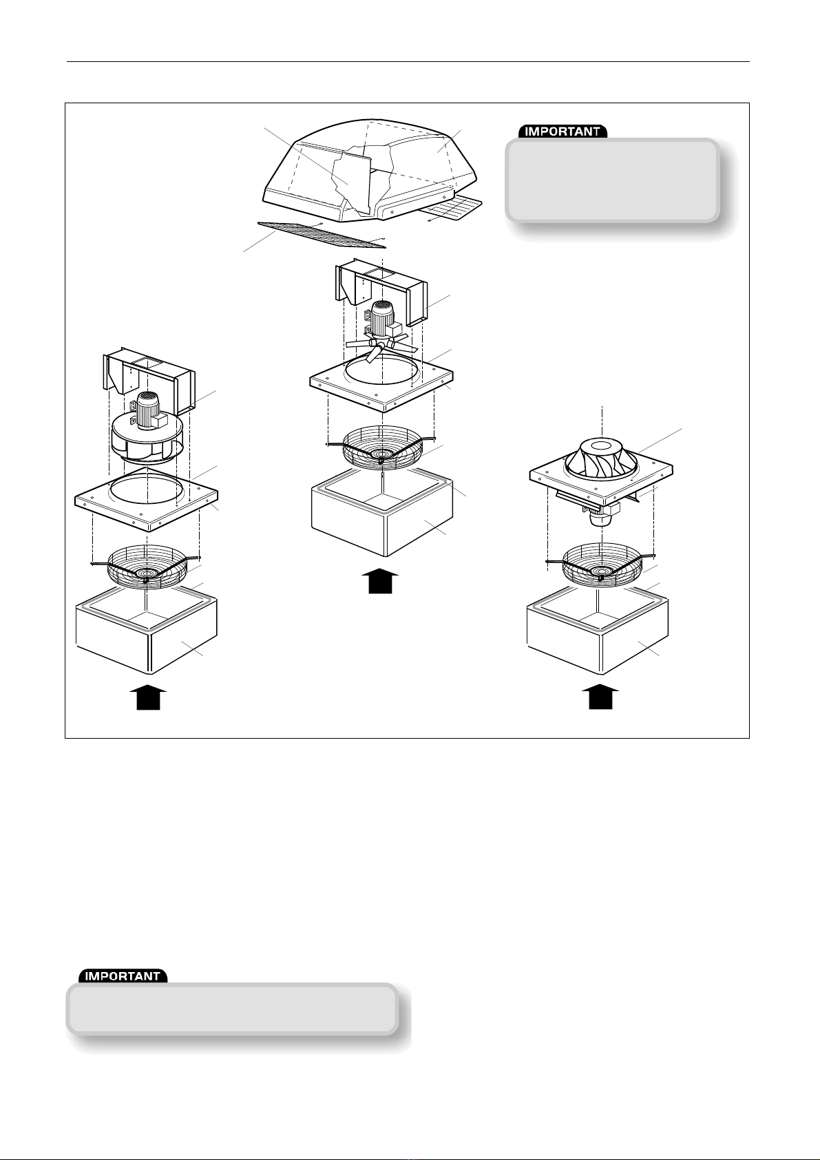
Each unit consists of a base incorporating a spun venturi plate,
a bridge* from which the motor and impeller are suspended and
a GRP cowl (fig. 1).
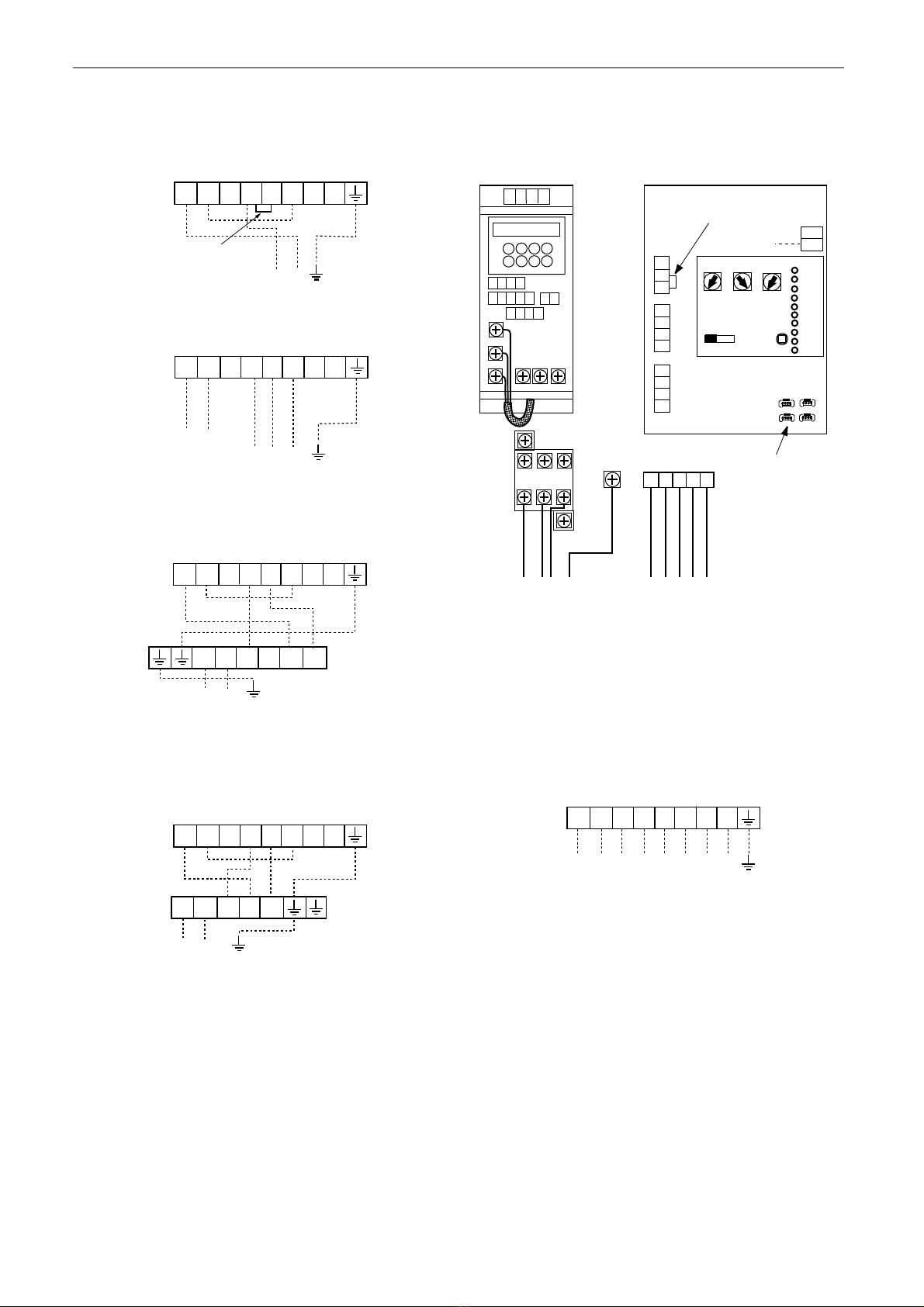
Motors are manufactured to BS5000, have sealed for life
bearings and have integral thermal protection which must be
incorporated into the control wiring. Failure to use this device
will invalidate the equipment warranty.
1.0 Handling
Units must at all times be handled carefully to avoid damage or
distortion. The unit is delivered fully assembled and mounted
on a pallet for ease of handling. When lifting or hoisting units,
care must be taken to ensure that no pressure is applied to the
cowl. Lifting eyes, suitable for all units, are available.
Purlin Box / Curb
Purlin box / curbs are manufactured in galvanised mild steel.
The upper face of the purlin box is fitted with a sealing strip.
When installed, the curb must be securely attached to the
trimmer angles.
Soaker Sheet
Soaker Sheets can be supplied by Nuaire. Manufactured in high
quality GRP, each sheet is 19500 mm long and can be supplied
to match most roof profiles. The soaker sheets are designed to
be used over a prefabricated curb.
2.0 Installation
The installation must be carried out by competent personnel in
accordance with the appropriate authority and conforming to all
statutory and governing regulations.
The unit is delivered completely assembled and a protective skin
prevents damage to the unit. It is strongly recommended that
this protective skin is allowed to remain in position for as long
as possible. When neccessary, the skin should be removed
using a sharp knife, taking care not to score the unit surface.
The unit can now be inspected for damage. Any accumulation of
dirt should be removed (see cleaning, page 6).
The unit is designed for roof mounting but can be wall mounted
using the optional wallkit available from Nuaire (see page 3).
2.1 Roof installation
Check that the curb mounting surface is flat and that the seal-
ing strip is in position. (A suitable mastic may be used as an
alternative).
If backdraught shutters or inlet side guards are to be fitted they
should be installed centrally in the curb.
Curbs other than Nuaire purlin box/curbs should be fitted with
timber capping. On timber capped curbs the units may be
attached using coachbolts or similar. When attaching to Nuaire
purlin box/curbs the use of TEK self drilling screws (type SF
46516) or self tapping screws is recommended.
Holes are provided in the skirt of the units base/venturi plate.
(See fig. 5).
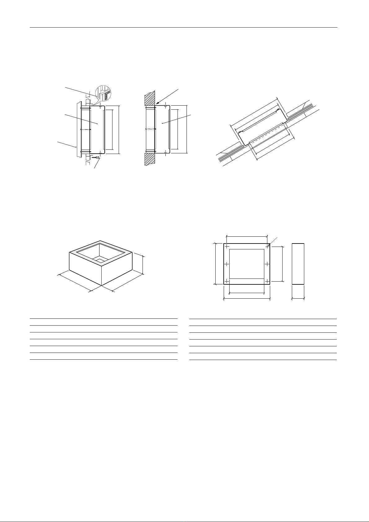
2.2 Wall installation
If still assembled, separate the unit and wall plate by removing
the screws and washers from around the unit skirt. Retain the
fixings. Depending on the type of wall, prepare a hole to the
dimensions shown on page 3. For a solid wall, fit the hole with
a timber frame as shown. Drill and fit appropriate wall plugs
and secure the timber frame. On completion, the frame must
be flush with the outside surface of the wall.
For installation to a profile sheet wall, fit a suitable timber
frame supported by means of angle-iron sections. The timber
frame should, on completion, be flush with the outside sheet
profile (Fig. 4).
Apply a flexible silicone sealer e.g. Flowseal 32 to the timber
frame and secure the wall plate using suitable coach bolts,
nuts and washers. On a solid wall installation, apply a fillet
of sealant between the wallplate and wall.
On profile walls it will be neccessary to ‘flash’ the wall plate.
Flashing strips should extend sufficiently to allow fixing to a
high portion of the profile section. Ensure that the flashing
strips over lap at the four corners. Fill between the top and
bottom flashing strips with Neoprene profile filler and seal all
external joints and seams with a suitable flexible silicone sealer
such as Flowsil 32. (See Wallplate dimensions fig. 4b).
1
12. 05. 17. Leaflet Number 670506
Terminator
TRA/TRM/TRC Roof Extract Fan
Installation and Maintenance
Figure 1. View of unit
The EMC Directive
2014/30/EU
The Low Voltage
directive
2014/35/EU
Nuaire: A Trading Division of Polypipe Limited Western Industrial Estate Caerphilly United Kingdom CF83 1NA

Installation and Maintenance Terminator Roof Extract Fans
2
12. 05. 17. Leaflet Number 670506
Cowl
Gravity operated shutters
End view
Bird guards
(optional)
Motorised Multi-Leaf
damper optional
Cable entry
E
Side view
D
M x M damper (opt.)
A x A min.
G x G inside weatherskirt
Curb
height L
F
Galvanised steel base frame
Fixing
centres
A x A min. Fan guard
Dimensions (mm) Unit and Roof Curb.
Cowl Dimensions in mm Cowl
unit weight
size A B C D E F G H J K L M kg
A 460 45 475 900 620 340 600 550 560 150 450 390 12.3
B 560 45 575 1080 740 375 695 650 660 150 450 490 14.7
C 700 100 775 1320 964 475 945 900 910 150 450 690 25.4
D 800 100 900 1470 1076 490 1050 1000 1010 200 500 800 28.2
E 900 100 1000 1780 1170 485 1150 1100 1110 250 650 900 48.8
F 1200 100 1300 2260 1476 600 1452 1400 1410 250 700 1200 88.0
NOTE: Dimensions etc. refer to Axial, Mixed Flow and Centrifugal units
See table CODING & COWLS below.
AXIAL (code TRA)
CENTRIFUGAL (code TRC)
MIXED FLOW (code TRM)
Figure 3. Roof Curb details (see dimensions in the table above).
3.0 Dimensions (mm) and Fixing Details
Figure 2.
Typical unit code
TR C S 450 -4 3
3 phase
4 pole
This is the unit size
(if only two digits e.g.
80 this is an 800 size)
Shutters
Centrifugal impeller
Terminator fan
Isolation - Before commencing work make sure that
the unit and Nuaire control if fitted are
electrically isolated from the mains supply.
Do not operate the unit with the cowl removed.
The impeller will continue to rotate after the supply has
been disconnected - allow sufficient time for the
impeller to come to rest.
Note: This table applies to all three unit
types TRA, TRC & TRM.
Unit Cowl
Size Size
315 A
350 A
400 B
450 B
500 C
560 C
630 D
710 D
800 E
1000 F
Coding & Cowls
Refer to table to find
cowl size.

Installation and Maintenance Terminator Roof Extract Fans
3
12. 05. 17. Leaflet Number 670506
Wall plate
Trimmer
Flashing strips
by others.
Neoprene
Profile Filler
Plastic capped self-tapping screws (by others).
A x A
Y x Y
Important that timber is flush with
outside of wall and secured with coach
bolts (by others).
Use Flowsil 32 flexible silicone sealant
filler on all joint faces to form a fillet
for complete weatherseal.
A x A
Y x Y
Wall plate
C x C
A x A
J x J
Y x Y
Wall Plate secured to a profile sheet. Brick or similar wall prepared to Roof profile prepared to accept
accept Wall Plate. a Purlin Box Curb
Dimensions and Fixing Details cont Figure 4.
XY
Z
E
A
C
A
D
B
Fixing centres
Dimensions (mm)
Code A B C D E
TRWP-A 550 250 400 369* 475
TRWP-B 650 250 500 470* 575
TRWP-C 900 250 700 610* 825
TRWP-D 1000 250 800 690** 900
TRWP-E 1100 350 900 780** 1000
TRWP-F 1400 325 1200 1080** 1300
* Three holes equally spaced. ** Four holes equally spaced.
Dimensions (mm)
Unit Curb Size X Y Z
PBC A 550 550 250
PBC B 650 650 250
PBC C 900 900 250
PBC D 1000 1000 250
PBC E 1100 1100 350
PBC F 1400 1400 325
Note: For Thermal Curb add T to code e.g. PBCT A, PBCT B etc.
Figure 4a. Purlin Box Curb. Figure 4b. Wall Frame Kit Dimensions (mm).

If the Terminator unit is to be used
with one of the Nuaire “drop in”
attenuators, the unit’s inlet guard
needs to be removed first.
Installation and Maintenance Terminator Roof Extract Fans
4
12. 05. 17. Leaflet Number 670506
Centrifugal
Axial Flow
Mixed Flow
Sealing strip
GRP cowl
Birdguards
(plastic coated
wire mesh)
Shutters
Base/Venturi plate
galvanised steel
Cowl fixing
threaded inserts
Fan inlet guard
(standard up to
unit size 630).
Optional for units
710 and above)
Purlin Box
Curb
Motor mounting
frame
(galvanised steel)
Base/Venturi plate
galvanised steel
Optional fan
inlet guard
Purlin Box
Curb
Motor mounting
frame
(galvanised steel)
Base/Venturi plate
galvanised steel
Cowl fixing
threaded inserts
Optional fan
inlet guard
Purlin Box
Curb
Motor mounting
frame
(galvanised steel)
Sealing strip
Sealing strip
Figure 5. Exploded view of unit showing the three different types of impeller available.
The unit must be provided with a means of isolation (by
others) for maintenance purposes etc. A suitable isolator
can be supplied by Nuaire on request as a separate item.
4.0 Electrical details
WARNING - DANGER
This equipment incorporates rotating and moving parts
as well as electrical components and conductors.
It is the responsibility of the installer to ensure that any
such items remaining externally accessible once the
equipment is installed are adequately guarded.
This precaution is necessary to avoid the possibility of
accidental injury or death.
Particular attention must be paid to the outlet side of the
rotating impellers if the cowl is removed.
4.1 Connecting the supply
Refer to the unit rating label attached to the motor venturi
plate.
Check that the electrical voltage and frequencies correspond to
those marked on the rating label.
Some units have a 600mm flexible conduit direct from the
motor terminated in a connector box. This should be mounted
in a convenient position next to the fan. Refer to the wiring
diagrams and connect the supply to the terminal box.
On other units the cowl must be removed to gain access to the
connection box. Remove and retain the cowls M8 setscrews
with the aluminium and nylon washers. Note: When birdguards
are fitted on larger units, remove the extra four M8 end bolt
fixings before removing the cowl.
Bring up the supply cables through the grommet provided in
the baseplate. Refer to the wiring diagrams (page 5) and
connect the supply to the unit terminal box which will be located
on the baseplate or the motor bridge assembly.
When replacing the cowl ensure that the nylon washer is
placed next to the cowl surface. If the four M8 end bolts are
fitted, ensure the birdguard fixing hooks are located correctly.
Note: the unit is not weather tight when cowl is removed.

Installation and Maintenance Terminator Roof Extract Fans
5
12. 05. 17. Leaflet Number 670506
4.2 Wiring for Terminator TRA, TRM, TRC (Except TRA 100H-43)
T1 T2 X L N
L N
230V 1 phase 50Hz supply
Fan
unit
NOTE:
Remove link between
X+L when using a
speed control (see below)
*Note: When T1 & T2 are fitted, connect as shown
(Single phase units - 3 wire supply)
Single Speed 1 Phase
230V 1 phase 50Hz supply
T1 T2 X L N
L N L2 N N L1
L N
Fan
unit
Control
NOTE:
Link removed between
X+L as shown when
using a speed control
*Note: When T1 & T2 are fitted, connect as shown.
Speed Control, Transformer 1 Phase
T1 T2 U1 V1 W1
L1 L2 L3
400V 3 phase 50Hz supply
Fan
unit
Do not
connect
To Starter
Control Circuit
(where fitted)
Single Speed 3 Phase
230V 1 phase 50Hz supply
L N L2 N L1
L N
Fan
unit
Control
X+L as shown when
using a speed control
*Note: When T1 & T2 are fitted, connect as shown.
T1 T2 X L N
Speed control, Electronic 1 Phase
4.3 Unit Wiring
The terminator range of units are pre-wired from the motor to
an enclosed terminal box.
On TRA (axial) models this box is located at the end of a
600mm long flexible conduit which hangs underneath and is
fixed to a convenient surface by the installer. These units will
require bottom access to complete wiring.
On TRM (mixed flow) and TRC (centrifugal) models the box is
located on the fan plate or motor bridge inside the cowl.
On these units it will be necessary to remove the cowl to gain
access.
When wiring in the unit take care to avoid rotating components
and also gravity shutters. 20mm holes are provided in the fan
base plate to bring wiring out from inside the building.
4.4 Connection details
Check that the electrical supply is compatible with the unit
(see unit rating plate).
Connection details are supplied with speed controls.
All wiring must be carried out in accordance with regulations
for electrical installations and comply with the requirements
of the local supply authority.
Ensure that the direction of rotation is correct. Single phase
units are checked during manufacture for correct rotation.
Three phase units must be tested on site and, if incorrect,
interchange any two supply leads to reverse impeller direction.
FAULT RUN
N
L
SL
Min Max SL run on
Trickle Test
0 1
Pwr
Standby
Fan 1
Fan 2
Heating
Cooling
Fault
Frost
Tx
Rx
Ecosmart
Earth
DAMPER
E N L1 L2 L3
Mains supply connections
400V 50Hz 3ph + Neutral
Via local isolator
1 3 5
2 4 6
(U) (V) (W)
L1 L2 L3 E
(U) (V) ( W)
L3
L2
L1
12 13 14 15
5 6 7 8 9 10 11
1 2 3 4
CONTACTER
A1
A2
0V
0-10V
BMS signal
'NET' connection
E N L1 L2 L3
U V W E
Connections to fan via screened
power cable. Purpose made glands
are provided to earth the screening
DP
CL
N
RET
Remove this link if:
1: A switched live signal is connected
2: A ES-PIR, ES-TC or BMS Signal is connected
Note: Internal connections
between the supply
terminals, output
contactors the PCB and
inverter are made at
the factory
Ecosmart
T1 T2 U1
400V 3phase & N supply
Fan
unit
To starter
Control Circuit
(230V max)
V1 W1 U2 V2 W2
Interchange any two supply
leads to reverse rotation
Unit Supplied for
Single speed operation
TRA100H-43 3 Phase
(Single phase units - 3 wire supply)
Note: The Ecosmart control box is a seperate item packed
individually. See installation leaflet 671193 for details of
Ecosmart Control (ES-ISC).

Do not operate the unit with the cowl removed.
The impeller will continue to rotate after the supply
has been disconnected - allow sufficient time for the
impeller to come to rest.
Before commencing work, ensure the unit is isolated
from the electrical supply. Also, see notes on safety
precautions above.
Installation and Maintenance Terminator Roof Extract Fans
6
12. 05. 17. Leaflet Number 670506
5.0 Routine Maintenance
Before attempting to carry out any work; ensure the unit and
speed control, if fitted, are electrically isolated.
Before proceeding, check that:-
Bird Guards (if fitted) are not distorted or obstructed in any
way.
Anti Backdraught Shutters operate correctly.
Impeller rotates freely and does not foul the fan plate.
The impeller is clean and free from wear.
The condition of all components is suitable for further service.
Also check condition and tightness of all fixings.
Note: the unit is not weather tight when cowl is removed.
Spare Parts
When ordering spare parts please quote the serial number of
the unit. Please fully describe the part. Serial number will be
found on the identification plate fixed to the unit.
5.1 Maintenance
Remove the cowl to gain access to the moving parts.
TRA (Axial) The impeller is accessible immediately and can be
removed if required.
TRC (Centrifugal) Motor/impeller bridge assembly can be
removed after releasing the 4 or 6 screws holding the bridge
support. On this unit the impeller cannot be removed from the
motor.
TRM (Mixed flow) Motor/impeller bridge assembly can be
removed after releasing the 4 or 6 screws holding the bridge
support. Invert the bridge and remove impeller if required
Removal of impeller (AXIAL) Ref: TRA
Knock up the tab washer and remove the retaining screw.
Remove the impeller from the motor shaft.
Retain the motor shaft key.
Replacement is the reversal of the above procedure.
Removal of impeller (CENTRIFUGAL) Ref: TRC
On this type of unit the impeller cannot be removed from the
motor. Cleaning of the impeller must be carried out in situ.
Removal of impeller (MIXED FLOW) Ref: TRM
On this type of unit the impeller is retained by a taperlock
fixing. To release the impeller, remove the grubscrews on each
side of the slit. Lightly lubricate one of the grubscrews and
insert it into the threaded hole opposite the slit (A).
Carefully tighten the grubscrew until the tapers ‘break’
allowing removal of the impeller. Remove the impeller.
AB
5.2 Replacement of the impeller
Place the impeller over the shaft and locate the taperlock in the
impeller. Insert and tighten the two grubscrews into the tapped
holes either side of the slit (B).
5.4 Cleaning the impeller
A build up of dust/dirt may be removed by brushing carefully
with a stiff brush. Take care not to damage or distort the
impeller blades. If the impeller is too badly fouled to allow
cleaning in situ, proceed as follows:-
1) Remove the impeller.
2) Remove all loose dirt using a stiff brush.
3) Sponge the impeller with warm soapy water.
4) Rinse thoroughly with clean water and wipe dry.
Do not use solvents or caustic fluids.
6.0 Spare Parts
When ordering spares please quote the serial number of the
unit together with the part number. If the part number is not
known please give a full description of the part required. The
serial number will be found on the identification plate attached
to the unit casing.
7.0 Warranty
Terminator has a 3 year warranty, Ecosmart Terminator has a
5 year warranty. The warranty starts from the day of delivery
and includes parts and labour for the first year.
The remaining period covers replacement parts only.
This warranty is void if the equipment is modified without
authorisation, is incorrectly applied, misused, disassembled, or
not installed, commissioned and maintained in accordance with
the details contained in this manual and general good practice.
The product warranty applies to the UK mainland and in
accordance with Clause 14 of our Conditions of Sale.
Customers purchasing from outside of the UK should contact
Nuaire International Sales office for further details.
8.0 After Sales Enquiries
For technical assistance or further product information,
including spare parts and replacement components, please
contact the After Sales Department.
Telephone 02920 858 400
5.3 Maintenance check list
Item Tick
Check that bird guards/safety grilles are secure
and free of obstruction.
Inspect all bolts, fixings and electrical terminals
for security.
Check motor for undue wear, signs of overheating
and apply winding insulation and continuity tests.
Remove all dust and dirt from impellers, be
especially careful not to disturb balance weights.
Generally clean.
Check resilient mounts and replace any that show
signs of wear or deterioration.

7
12. 05. 17. Leaflet Number 670506
To comply with EC Council Directives 2006/42/EC Machinery Directive and
2014/30/EU (EMC).
To be read in conjunction with the relevant Product Documentation (see 2.1)
1.0 GENERAL
1.1 The equipment referred to in this Declaration of Incorporation is supplied by
Nuaire to be assembled into a ventilation system which may or may not include
additional components.
The entire system must be considered for safety purposes and it is the
responsibility of the installer to ensure that all of the equipment is installed in
compliance with the manufacturers recommendations and with due regard to
current legislation and codes of practice.
2.0 INFORMATION SUPPLIED WITH THE EQUIPMENT
2.1 Each item of equipment is supplied with a set of documentation which provides
the information required for the safe installation and maintenance of the
equipment. This may be in the form of a Data sheet and/or Installation and
Maintenance instruction.
2.2 Each unit has a rating plate attached to its outer casing. The rating plate
provides essential data relating to the equipment such as serial number, unit
code and electrical data. Any further data that may be required will be found
in the documentation. If any item is unclear or more information is required,
contact Nuaire.
2.3 Where warning labels or notices are attached to the unit the instructions given
must be adhered to.
3.0 TRANSPORTATION, HANDLING AND STORAGE
3.1 Care must be taken at all times to prevent damage to the equipment. Note that
shock to the unit may result in the balance of the impeller being affected.
3.2 When handling the equipment, care should be taken with corners and edges and
that the weight distribution within the unit is considered. Lifting gear such as
slings or ropes must be arranged so as not to bear on the casing.
3.3 Equipment stored on site prior to installation should be protected from the
weather and steps taken to prevent ingress of contaminants.
4.0 OPERATIONAL LIMITS
4.1 It is important that the specified operational limits for the equipment are
adhered to e.g. operational air temperature, air borne contaminants and unit
orientation.
4.2 Where installation accessories are supplied with the specified equipment eg.
wall mounting brackets. They are to be used to support the equipment only.
Other system components must have separate provision for support.
4.3 Flanges and connection spigots are provided for the purpose of joining to
duct work systems. They must not be used to support the ductwork.
5.0 INSTALLATION REQUIREMENTS
In addition to the particular requirements given for the individual product, the
following general requirements should be noted.
5.1 Where access to any part of equipment which moves, or can become electrically
live are not prevented by the equipment panels or by fixed installation detail
(eg ducting), then guarding to the appropriate standard must be fitted.
5.2 The electrical installation of the equipment must comply with the requirements
of the relevant local electrical safety regulations.
5.3 For EMC all control and sensor cables should not be placed within 50mm or on
the same metal cable tray as 230V switched live, lighting or power cables and
any cables not intended for use with this product.
6.0 COMMISSIONING REQUIREMENTS
6.1 General pre-commissioning checks relevant to safe operation consist of the
following:
Ensure that no foreign bodies are present within the fan or casing.
Check electrical safety. e.g. Insulation and earthing.
Check guarding of system.
Check operation of Isolators/Controls.
Check fastenings for security.
6.2 Other commissioning requirements are given in the relevant product documentation.
7.0 OPERATIONAL REQUIREMENTS
7.1 Equipment access panels must be in place at all times during operation of the
unit, and must be secured with the original fastenings.
7.2 If failure of the equipment occurs or is suspected then it should be taken out of
service until a competent person can effect repair or examination. (Note that
certain ranges of equipment are designed to detect and compensate for fan failure).
8.0 MAINTENANCE REQUIREMENTS
8.1 Specific maintenance requirements are given in the relevant product documentation.
8.2 It is important that the correct tools are used for the various tasks required.
8.3 If the access panels are to be removed for any reason the electrical supply to the
unit must be isolated.
8.4 A minium period of two minutes should be allowed after electrical disconnection
before access panels are removed. This will allow the impeller to come to rest.
NB: Care should still be taken however since airflow generated at some
other point in the system can cause the impeller to “windmill” even when
power is not present.
8.5 Care should be taken when removing and storing access panels in windy
conditions.
INFORMATION FOR SAFE INSTALLATION, OPERATION AND MAINTENANCE
OF NUAIRE VENTILATION EQUIPMENT
DECLARATION OF INCORPORATION AND INFORMATION FOR SAFE INSTALLATION,
OPERATION AND MAINTENANCE
We declare that the machinery named below is intended to be assembled
with other components to constitute a system of machinery. All parts
except for moving parts requiring the correct installation of safety
guards comply with the essential requirements of the Machinery Directive.
The machinery shall not be put into service until the system has been
declared to be in conformity with the provisions of the EC Machinery
Directive.
Designation of machinery: Terminator Roof Extract Fans
Machinery Types: TRA, TRM, TRC
Relevant EC Council Directives: 2006/42/EC (Machinery Directive)
Applied Harmonised Standards: BS EN ISO 12100-1, BS EN ISO 12100-2,
EN60204-1, BS EN ISO 9001,
BS EN ISO 13857
Applied National Standards: BS848 Parts 1, 2.2 and 5
Note: All standards used were current and valid at the date of signature.
Signature of manufacture representatives:
Name: Position: Date:
1) C. Biggs Technical Director 26. 01. 11
2) A. Jones Manufacturing Director 26. 01. 11
This manual suits for next models
2
Table of contents
Popular Automobile Accessories manuals by other brands

Thule
Thule 1345 instruction manual

Jaeger
Jaeger 26500505J manual

Wilson Electronics
Wilson Electronics Cell Phone Cradle installation guide

Rockford Fosgate
Rockford Fosgate Polaris PMX-P2 Operation manual

Over Armour Offroad
Over Armour Offroad HO-700-WD05 Instructions for Installation and Care

DNT
DNT RFK Integro 3.5 user manual