manuals.online logo
Brands
  1. Home
  2. •
  3. Brands
  4. •
  5. NuAire
  6. •
  7. Fan
  8. •
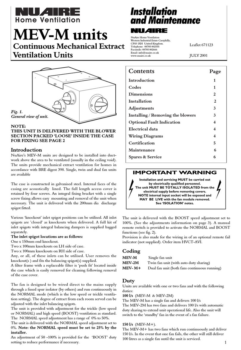
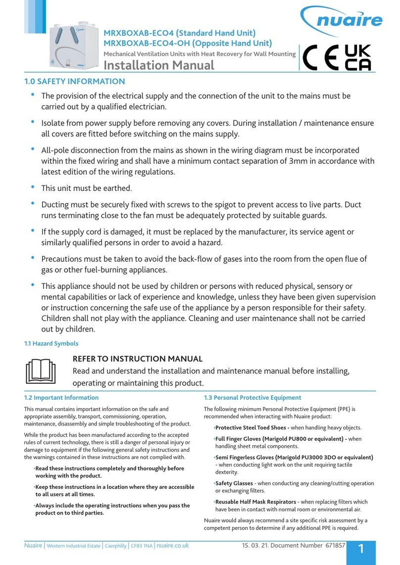
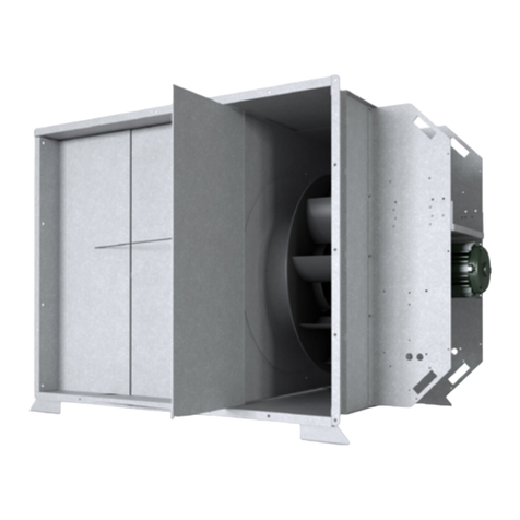
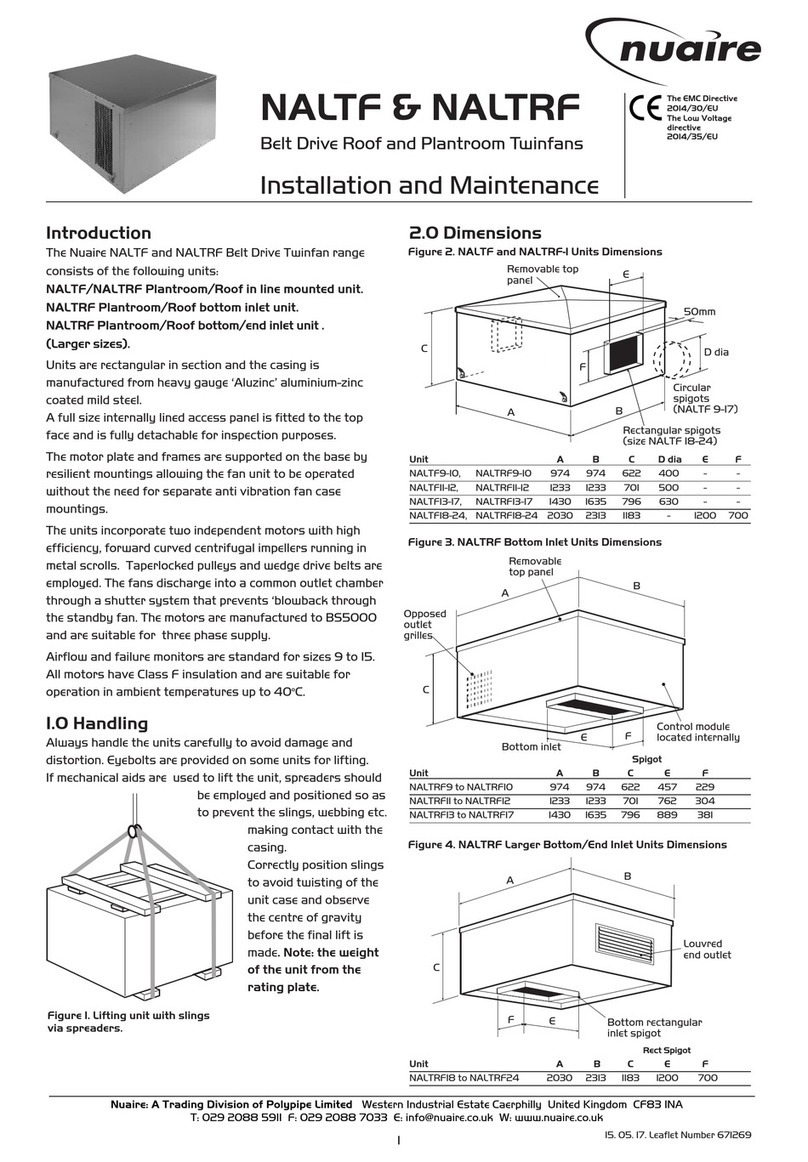
  9. NuAire SLIMAIRE/NA Series Instruction Manual

NuAire SLIMAIRE/NA Series Instruction Manual

Nuaire Limited Western Industrial Estate Caerphilly United Kingdom CF83 1NA
T: 029 2088 5911 F: 029 2085 8444 E: [email protected] W: www.nuaire.co.u
SLIMAIRE/NA 12V and
230V Slimline Axial Fans
Installation and Maintenance
The EMC Directive
2004/108/EC
The Low Voltage
directive
2006/95/EC
Isolation - Before commencing wor
ma e sure that the unit is electrically isolated
from the mains and switched live supply.
108. 12. 14. Leaflet Number 671420
Figure 1. Components
Component Key
1. Front Cover
2. Wall Fixing Screws
3. Motor Fan Assembly
4. Front Cover Fixing
Screw
5. Wall Plug
6. Cable Grommet
7. Cable Clamp
8. Cable Fixing Screws
9. Outside Grille
(by others)
Figure 2. Wall Installation with
outside grille
123 4 5
8 7 6
6mm dia.
9
SLIMAIRE/NA Fans
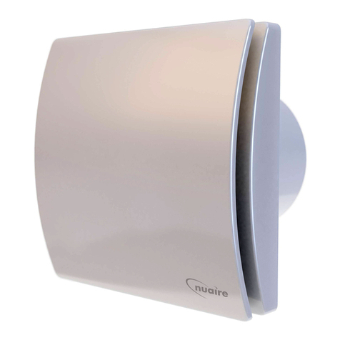
The Nuaire slimline range of axial fans incorporates 12 models.
These IPX4-Splashproof fans have been specifically designed
to ventilate small rooms such as toilets, bathrooms, shower
rooms, utility rooms and itchens and are ideal for wall, ceiling
or panel installation. The units extract directly to outside or
through a short length of ducting.
Fan Coding and range
SLIMAIRE/NA Standard version operated by
100/150 remote switch.
SLIMAIRE/NA Standard version operated by
100PC/150PC pull cord.
SLIMAIRE/NA With integral overrun timer - the fan should
100T/150T be operated by a remote switch which can
also serve to switch the room light on and
off. After the light is switched off, the fan
will continue to operate for a minimum of 3
minutes (adjustable to a maximum of 25
minutes) by turning the trimmer (Fig 5) in a
cloc wise direction.
SLIMAIRE/NA With integral humidistat and overrun timer -
100HT/150HT the adjustable, electronic humidistat is
pre-set so that the fan will operate
automatically when the moisture content in
the room reaches a pre-set level of relative
humidity. The fan will continue to run until
the relative humidity falls below the pre-set
level. This level can be adjusted by turning
the trimmer (Fig 6) on the fan.
This fan can be operated by a remote switch
or light switch allowing operation of the fan
independently of the humidistat.
The overrun timer, which will always ma e
the fan continue to operate for the pre-set
length of time even after it has been
manually switched off, can be adjusted as
described above.
SLIMAIRE/NA With integral sensor and overrun timer - the
100PIR/150PIR fan will start to operate automatically when
it detects the presence of a person. After
the room is vacated, the fan will continue to
operate for a minimum of 3 minutes
(adjustable to a maximum of 25 minutes) by
turning the trimmer in an anti-cloc wise
direction (Fig 7).
SLIMAIRE/NA This version must be installed using the
100-12 12V version remote transformer supplied
(see current IEE Regulations for guidance).
SLIMAIRE/NA With integral overrun timer adjusted as
100T-12 12V version above. This version must be installed using
the remote transformer supplied
(see current IEE Regulations for guidance).
Note: A neon indicator is incorporated on the front of some
models to indicate that the fan is operating.
Fan Installation
Installation should be carried out by competent personnel in
accordance with the appropriate authority and conforming to all
statutory and governing regulations.
The product should not be used in an ambient temperature higher
than 40°C (104°F) and should not be exposed to atmospheric
agents (rain, sun, snow, etc). The product or any part of it should
not be placed in water or other liquids.
Siting Information
1. Remove the fan from the box, ta ing care to dispose of the
pac ing material properly.
2. Chec the location of existing wiring for ease of connection and
that the voltage and frequency correspond with those mar ed
on the fan rating label.
3. For optimum performance site the fan a minimum of 2.3m above
ground level and should be away from a heat source (e.g. a
heater), any direct light (sunlight, lamp etc) or any air conditioning
unit. Care should be ta en to ensure that the sensor (PIR unit)
is free of any obstruction (such as a cupboard).
4. LV models must be installed using the remote transformer,
which should be sited outside the scope of any water source
(see current IEE Regulations for guidance).
5. The fan must not be used in an ambient temperature higher than
40OC.
6. Use the appropriate size core cutter to obtain a hole diameter
of 100mm or 150mm in the wall/ceiling allowing if necessary for
the thic ness of any ducting to be used.
7. The fan must not be exhausted into a duct which is already
used for any other purpose (see Approved Document F1 2006
for guidance).
8. Dismantle the fan:
a. Remove the front cover (1) by unscrewing front fixing screw (4).
b. Using the Motor Fan Assembly (3) of the fan as a template,
mar the hole drilling positions to fix the fan to the wall or
ceiling.
c. Drill the fixing holes and using the wall plugs and long screws
provided, fix the Motor Fan Assembly (3) to the wall/ceiling.
9. Note: Before fixing the
fan to the wall/ceiling, decide
whether to have the cable
entering the fan through the
noc ed-out hole on the top
of the Motor Fan Assembly
or through the bac of the
Motor Fan Assembly. In the
first case the included cable
clamp and grommet will need
to be used. In the second
option the cable entry hole
will need to be noc ed out.
10. With the front cover
removed connect the mains
supply cable to the terminal
bloc then replace front
cover of the Fan.
Timer and humidistat adjustment
208. 12. 14. Leaflet Number 671420
Installation and Maintenance SLIMAIRE/NA 12V & 230V Slimline Axial Fans
Figure 5. Timer adjustment for “T” models
Performance details
Model m3/hr Pa W dBa @3m
SLIMAIRE/NA 100 230V 95 24 11 40
SLIMAIRE/NA 150 230V 290 67 26 49
Figure 3. Top cable noc out &
cable grommet
Figure 4. Rear cable noc out
Figure 6. Humidistat/Timer adjustment for “HT” models
Figure 7. Timer adjustment for “PIR” models
Figure 8. “PIR” Detection Area
(m)
3.03.0
2.0
1.0
0
3.0
2.0
1.0
1.0 2.0 3.0 4.0 5.0 6.0 (m)
+50o
+40o
+50o
+20
+10o
-30o
-40o
-50o
-20
o
-10o
0
CF1F2
E1
E2
D
D1 - D2
A
C
E1
E2
F1 F2
D
D1 - D2
01.0 2.0 3.0 4.0 5.0 6.0 (m)
3.0
2.0
1.0
4.0
(m)
+30o
+20
-30o
-20
o
F2 - F2
D1 - D1
E1 - E1
F1 - F1
D1 - D1
C- C E1 - E1 D - D
0
A
F1F1
F2 F2
C
CDD
A
D1D1 E1E1
E2E2
D2D2
o
o
0
(m)
3.03.0
2.0
1.0
0
3.0
2.0
1.0
1.0 2.0 3.0 4.0 5.0 6.0 (m)
+50o
+40o
+50o
+20
+10o
-30o
-40o
-50o
-20
o
-10o
0
CF1F2
E1
E2
D
D1 - D2
A
C
E1
E2
F1 F2
D
D1 - D2
01.0 2.0 3.0 4.0 5.0 6.0 (m)
3.0
2.0
1.0
4.0
(m)
+30o
+20
-30o
-20
o
F2 - F2
D1 - D1
E1 - E1
F1 - F1
D1 - D1
C - C E1 - E1 D - D
0
A
F1F1
F2 F2
C
CDD
A
D1 D1 E1E1
E2E2
D2 D2
o
o
0
(m)
3.03.0
2.0
1.0
0
3.0
2.0
1.0
1.0 2.0 3.0 4.0 5.0 6.0 (m)
+50o
+40o
+50o
+20
+10o
-30o
-40o
-50o
-20
o
-10o
0
CF1 F2
E1
E2
D
D1 - D2
A
C
E1
E2
F1 F2
D
D1 - D2
01.0 2.0 3.0 4.0 5.0 6.0 (m)
3.0
2.0
1.0
4.0
(m)
+30o
+20
-30o
-20
o
F2 - F2
D1 - D1
E1 - E1
F1 - F1
D1 - D1
C - C E1 - E1 D- D
0
A
F1F1
F2 F2
C
CDD
A
D1 D1E1E1
E2E2
D2 D2
o
o
0
Isolation - Before commencing wor
ma e sure that the unit is electrically isolated
from the mains and switched live supply.
308. 12. 14. Leaflet Number 671420
Installation and Maintenance SLIMAIRE/NA 12V & 230V Slimline Axial Fans
L
N
L
N
Double Pole Isolator
L
N
L
N
L
N
L
N
T
Triple Pole Isolator
L
N
L
N
Double Pole Isolator
L
N
T
Fan unit
L N
12V
L N
230V
Fan unit
L N
12V
L N
230V
N
L
Transformer Transformer
Double Pole Isolator
N
L230V
~
50Hz
230V
~
50Hz
230V
~
50Hz
230V
~
50Hz
230V
~
50Hz
N
L
Triple Pole Isolator
230V
~
50Hz
L
N
L
N
Double Pole Isolator
L
N
L
N
L
N
L
N
T
Triple Pole Isolator
L
N
L
N
Double Pole Isolator
L
N
T
Fan unit
L N
12V
L N
230V
Fan unit
L N
12V
L N
230V
N
L
Transformer Transformer
Double Pole Isolator
N
L230V
~
50Hz
230V
~
50Hz
230V
~
50Hz
230V
~
50Hz
230V
~
50Hz
N
L
Triple Pole Isolator
230V
~
50Hz
Figure 10.
SLIMAIRE/NA 100/150 with remote switch.
Figure 12.
SLIMAIRE/NA 100T/100HT/150T/150HT via light
switch/ remote switch.
L
N
L
N
Double Pole Isolator
L
N
L
N
L
N
L
N
T
Triple Pole Isolator
L
N
L
N
Double Pole Isolator
L
N
T
Fan unit
L N
12V
L N
230V
Fan unit
L N
12V
L N
230V
N
L
Transformer Transformer
Double Pole Isolator
N
L230V
~
50Hz
230V
~
50Hz
230V
~
50Hz
230V
~
50Hz
230V
~
50Hz
N
L
Triple Pole Isolator
230V
~
50Hz
Figure 13.
SLIMAIRE/NA 100/150HT and PIR with Humidistat and
Integral sensor only.
Wiring details
It is recommended that the installation be carried out by a qualified
electrician.
All electrical connections must
comply with current IEE wiring
regulations. The fan is a fixed
appliance, and the electrical supply
must therefore be by a fixed wired
and fused (3 amp) spur
incorporating a double or triple
pole switch with contact openings
of at least 3mm.
Use twin conductor cable of at least 1mm3 in section (see Fig 9).
The fan is double insulated and does not require earthing.
The fan complies with current electrical safety regulations (IE64,
CENELEC 384), including EEC Directive EMC2004/108/CE
concerning the suppression of radio interference and
electromagnetic compatibility, and LVD2006/95/CE.
The fan must not be used as a switch for water heaters, stoves etc.
The printed circuit board in these fans has been protected to ma e
it compatible with the majority of fluorescent fittings available on
the mar et today. However, it is impossible to be aware of all new
products introduced. We suggest, therefore, that you contact your
supplier to establish the compatibility of any fluorescent fittings
you intend to use.
L
N
L
N
Double Pole Isolator
L
N
L
N
L
N
L
N
T
Triple Pole Isolator
L
N
L
N
Double Pole Isolator
L
N
T
Fan unit
L N
12V
L N
230V
Fan unit
L N
12V
L N
230V
N
L
Transformer Transformer
Double Pole Isolator
N
L230V
~
50Hz
230V
~
50Hz
230V
~
50Hz
230V
~
50Hz
230V
~
50Hz
N
L
Triple Pole Isolator
230V
~
50Hz
Figure 11.
SLIMAIRE/NA 100PC/150PC with pullcord.
L
N
L
N
Double Pole Isolator
L
N
L
N
L
N
L
N
T
Triple Pole Isolator
L
N
L
N
Double Pole Isolator
L
N
T
Fan unit
L N
12V
L N
230V
Fan unit
L N
12V
L N
230V
N
L
Transformer Transformer
Double Pole Isolator
N
L230V
~
50Hz
230V
~
50Hz
230V
~
50Hz
230V
~
50Hz
230V
~
50Hz
N
L
Triple Pole Isolator
230V
~
50Hz
Figure 14.
SLIMAIRE/NA 100-12 Must be installed with remote trans-
former.
L
N
L
N
Double Pole Isolator
L
N
L
N
L
N
L
N
T
Triple Pole Isolator
L
N
L
N
Double Pole Isolator
L
N
T
Fan unit
L N
12V
L N
230V
Fan unit
L N
12V
L N
230V
N
L
Transformer Transformer
Double Pole Isolator
N
L230V
~
50Hz
230V
~
50Hz
230V
~
50Hz
230V
~
50Hz
230V
~
50Hz
N
L
Triple Pole Isolator
230V
~
50Hz
Figure 15.
SLIMAIRE/NA 100T-12 via light switch (or remote switch).
Must be installed with remote transformer.
Figure 9. Twin conductor cable
408. 12. 14. Leaflet Number 671420
Installation and Maintenance SLIMAIRE/NA 12V & 230V Slimline Axial Fans
General Installation Precautions
Following these installation instructions will ensure the reliability
of the product and extend its wor ing life.
1. Remove the product from its pac aging and ma e sure that it
has not been damaged. If in doubt, contact the supplier,
authorised dealer, service centre or manufacturer to chec that
the product will still operate correctly. Do not attempt to use or
repair the product before doing this.
2. Do not leave pac ing material within the reach of children or
uns illed people, or dump any hazardous parts into the
environment (polystyrene, plastic, polypropylene, etc.).
3. The use of any electrical product requires compliance with some
basic rules which are listed below:
- do not touch it with wet or damp parts of the body
(e.g hands, feet).
- this product is not intended for use by persons (including
children) with reduced physical, sensory or mental capabilities
or lac of experience and nowledge, unless they have been
given supervision or instruction concerning the use of the
product by a person responsible for their safety. It should be
sited where it is inaccessible to such people.
- children should be supervised to ensure they do not play with
the product.
4. The product should be connected to the mains electricity supply
or electrical outlet only if:
- the electrical voltage and frequency correspond to those
shown on the rating label.
- the capacity of the electricity supply is sufficient to operate
the product at its maximum power.
- suitable electrical protection must be provided for the product
to be installed.
5. The electrical supply to which the fan is connected must comply
with all existing regulations. All installations must comply with
current IEE wiring regulations.
6. Before maintenance or cleaning is carried out, the product must
be switched off and disconnected from the mains electricity
supply.
7. If a fault, malfunction or anomaly of any type occurs, the fan
should be isolated (by turning off the switch and disconnecting
it from the mains electricity supply) and advice sought from
qualified personnel.
8. Always request original spare parts to effect any repairs.
9. If the product needs to be removed, turn off the mains supply
circuit-brea er and then disconnect the fan.
10. The fan MUST BE installed as detailed in this document.
Special Precautions
1. This product is professionally manufactured and complies with
the current standards regarding electrical equipment.
2. The product complies with the Low Voltage Directive and with
EC Directive EMC 204/108/CE for the Suppression of Radio
Interference.
3. Routine maintenance as described below should be carried out
to chec the condition of the fan.
4. To avoid the ris of fire, do not use the product in the presence
of flammable substances or vapours such as alcohol,
insecticides, petrol, etc.
5. The air or fumes being extracted must be clean and free from
greasy particles, soot, chemical and corrosive agents,
flammable or explosive mixes (If these substances are to be
extracted, contact an authorised dealer for specific range of
explosion-proof products).
6. The product must be connected to the electricity supply via a
double pole switch of a suitable size, with contact openings of
at least 3 mm.
7. If the electrical supply board (or switching device) is located
some distance from the fan a means of local isolation must be
provided.
8. To ensure optimum operation, do not bloc the air inta e and
exit vents.
9. Any ducting used must be free of bloc ages.
10. The room where the product is operating must have adequate
air replacement to ensure maximum effectiveness.
11. If the product is sited in a room containing a fuel burning
appliance which is not of the balanced flue type, the installer
must ensure that air replacement is adequate both for the fan
and the fuel burning appliance.
12. The product must not be used as an activator for water
heaters, stoves, etc.
13. The product must not exhaust into ducts designed to evacuate
fumes from combustion in stoves or other combustion-powered
devices.
Technical or commercial considerations may, from time to time, ma e it necessary to alter the design, performance and
dimensions of equipment and the right is reserved to ma e such changes without prior notice.
Maintenance
General
Before any maintenance or cleaning operation, switch off the fan
and disconnect from the main power supply.
The front cover can be cleaned with a dry cloth. Any other
maintenance or cleaning should be carried out by properly qualified
personnel.
The front cover can be removed and cleaned with water and a mild
detergent using a soft cloth and the motor fan assembly can be
cleaned with a dry brush or dry cloth. Ensure the unit does not
come into contact with any ind of liquid or solvent. If this should
occur, contact a qualified technician before reassembling the fan.
Note: The motor does not require lubrication as it is
maintenance free "sealed for life" type.
Replacement of Parts
Should any component need replacing Nuaire eep extensive stoc s
for quic delivery. Ensure that the unit is electrically isolated,
before carrying out any wor . When ordering spare parts, please
quote the serial number of the unit and the ARC number of the
purchase if possible (This information is located on the fan label).
Warranty
The 1 year warranty starts from the day of delivery.
Service Enquiries
Nuaire can assist you in all aspects of service. Our Technical
Support department will be happy to provide any assistance
required, initially by telephone and If necessary arrange for an
engineer to call.
Technical Support Department
on 029 2085 8400
This manual suits for next models

12

Other NuAire Fan manuals

NuAire DRI-365 User manual

NuAire

NuAire DRI-365 User manual

NuAire MRXBOX95B-350 WC Instruction Manual

NuAire

NuAire MRXBOX95B-350 WC Instruction Manual

NuAire MRXBOXAB-ECO5 User manual

NuAire

NuAire MRXBOXAB-ECO5 User manual

NuAire MRXBOXAB-ECO-LP2SW Instruction Manual

NuAire

NuAire MRXBOXAB-ECO-LP2SW Instruction Manual

NuAire MRXBOX95-WM1 User manual

NuAire

NuAire MRXBOX95-WM1 User manual

NuAire MRXBOXAB-ECO3-AESW User manual

NuAire

NuAire MRXBOXAB-ECO3-AESW User manual

NuAire MRXBOXAB-ECO3-1ZSW User manual

NuAire

NuAire MRXBOXAB-ECO3-1ZSW User manual

NuAire MRXBOXAB-ECO3-SW User manual

NuAire

NuAire MRXBOXAB-ECO3-SW User manual

NuAire DRI-ECOSMART/1 Installation guide

NuAire

NuAire DRI-ECOSMART/1 Installation guide

NuAire DRIMASTER 365 Installation guide

NuAire

NuAire DRIMASTER 365 Installation guide

NuAire FLAT2000L Instruction Manual

NuAire

NuAire FLAT2000L Instruction Manual

NuAire DE Seies User manual

NuAire

NuAire DE Seies User manual

NuAire CYFAN-C Instruction Manual

NuAire

NuAire CYFAN-C Instruction Manual

NuAire MRXBOXAB-ECO-LP1SW Instruction Manual

NuAire

NuAire MRXBOXAB-ECO-LP1SW Instruction Manual

NuAire FLAT2000L Instruction Manual

NuAire

NuAire FLAT2000L Instruction Manual

NuAire EST 19H-R Instruction Manual

NuAire

NuAire EST 19H-R Instruction Manual

NuAire MRXBOXAB-ECO3-SW User manual

NuAire

NuAire MRXBOXAB-ECO3-SW User manual

NuAire MRXBOX-ECO User manual

NuAire

NuAire MRXBOX-ECO User manual

NuAire ES-OPUSDC Series User manual

NuAire

NuAire ES-OPUSDC Series User manual

NuAire XSWA Series User manual

NuAire

NuAire XSWA Series User manual

NuAire XS6FR User manual

NuAire

NuAire XS6FR User manual

NuAire MRXBOX-ECO2 User manual

NuAire

NuAire MRXBOX-ECO2 User manual

NuAire MEV-ECO User manual

NuAire

NuAire MEV-ECO User manual

NuAire XBOXER Series User manual

NuAire

NuAire XBOXER Series User manual

Popular Fan manuals by other brands

inVENTer aV160 ALD Operating and cleaning instructions

inVENTer

inVENTer aV160 ALD Operating and cleaning instructions

Vent-Axia Lo-Carbon Revive Series Installation and wiring instructions

Vent-Axia

Vent-Axia Lo-Carbon Revive Series Installation and wiring instructions

Vortice CA-V0 Instruction booklet

Vortice

Vortice CA-V0 Instruction booklet

NOMA MILTON 052-9717-8 user manual

NOMA

NOMA MILTON 052-9717-8 user manual

Monte Carlo Fan Company Melody 3MER56 D Series Owner's guide and installation manual

Monte Carlo Fan Company

Monte Carlo Fan Company Melody 3MER56 D Series Owner's guide and installation manual

Marley RE-VENTI MS125E DC Operating & assembly instructions

Marley

Marley RE-VENTI MS125E DC Operating & assembly instructions

HeroCamper HEAT 1500+ Installation guide and user's manual

HeroCamper

HeroCamper HEAT 1500+ Installation guide and user's manual

Ruck Ventilatoren MPC T30 Series Assembly instruction

Ruck Ventilatoren

Ruck Ventilatoren MPC T30 Series Assembly instruction

SonicAire MOBILE Series owner's manual

SonicAire

SonicAire MOBILE Series owner's manual

Home Decorators Collection SFL-550L1 Use and care guide

Home Decorators Collection

Home Decorators Collection SFL-550L1 Use and care guide

Emerson CF921ORB00 owner's manual

Emerson

Emerson CF921ORB00 owner's manual

Vortice CA 125 MD Instruction booklet

Vortice

Vortice CA 125 MD Instruction booklet

Exhausto VEX260H manual

Exhausto

Exhausto VEX260H manual

Flair Smart Vent installation guide

Flair

Flair Smart Vent installation guide

Clatronic TVL 3770 instruction manual

Clatronic

Clatronic TVL 3770 instruction manual

Fantech Jetstream JCE150SJK CONTENTS & INSTALLATION INSTRUCTIONS

Fantech

Fantech Jetstream JCE150SJK CONTENTS & INSTALLATION INSTRUCTIONS

Goldair GCPF400 operating instructions

Goldair

Goldair GCPF400 operating instructions

AERMEC fcl Directions for use

AERMEC

AERMEC fcl Directions for use

manuals.online logo
manuals.online logoBrands
  • About & Mission
  • Contact us
  • Privacy Policy
  • Terms and Conditions

Copyright 2025 Manuals.Online. All Rights Reserved.