NuAire Allergard A Series User manual

OM0312
Allergard Class I
Animal Bedding Disposal Cabinet
Models:
NU-608-400E (Series A)
Operation and Maintenance Manual
April, 2021
Revision 1
Manufactured By:
NuAire, Inc.
2100 Fernbrook Lane
Plymouth, MN 55447
Toll-Free: 1-800-328-3352
In Minnesota: (763)-553-1270
Fax: (763)-553-0459

OM0312
2
Allergard Class I
Animal Bedding Disposal Cabinet
Models
NU-608-400E
Operation and Maintenance Manual
Table of Contents
Section No. 1....................................................................General Description
Section No. 2....................................................................Models and Features
Section No. 3....................................................................Warranty
Section No. 4....................................................................Shipments
Section No. 5....................................................................Installation Instructions
5.1......................................................................................Location
5.2......................................................................................Set-Up Instructions
5.3......................................................................................Electrical Services
5.4………………………………………………………………………………….Certification Testing Methods and Equipment
Section No. 6....................................................................Operating the NU-608
6.1…………………………………………………………………………………..Aeromax Control System
6.2…………………………………………………………………………………..Operating Guidelines
6.3…………………………………………………………………………………..Bag Installation and Removal
6.4.......................................................................................Ergonomics
6.5.......................................................................................Cleaning Procedures
Section No. 7....................................................................General Maintenance
7.1.......................................................................................Decontamination
7.2.......................................................................................LED Lamp Replacement
7.3.......................................................................................Filter Replacement
7.4.......................................................................................Motor/Blower Replacement
7.5.......................................................................................Airflow Calibration
7.6.......................................................................................Filter Integrity Check
Section No. 8 ...................................................................Error Messages, Troubleshooting and Option-Diagnostics
Section No. 9………………………………………………………………..Remote Contacts
Section No. 10..................................................................Polycarbonate Material Compatibility
Section No. 11……………………………………………………………….Electrical/Environmental Requirements
Section No. 12……………………………………………………………….Disposal and Recycle
Insert……………………………………………………………..………………Replacement Parts List
Standard Drawings
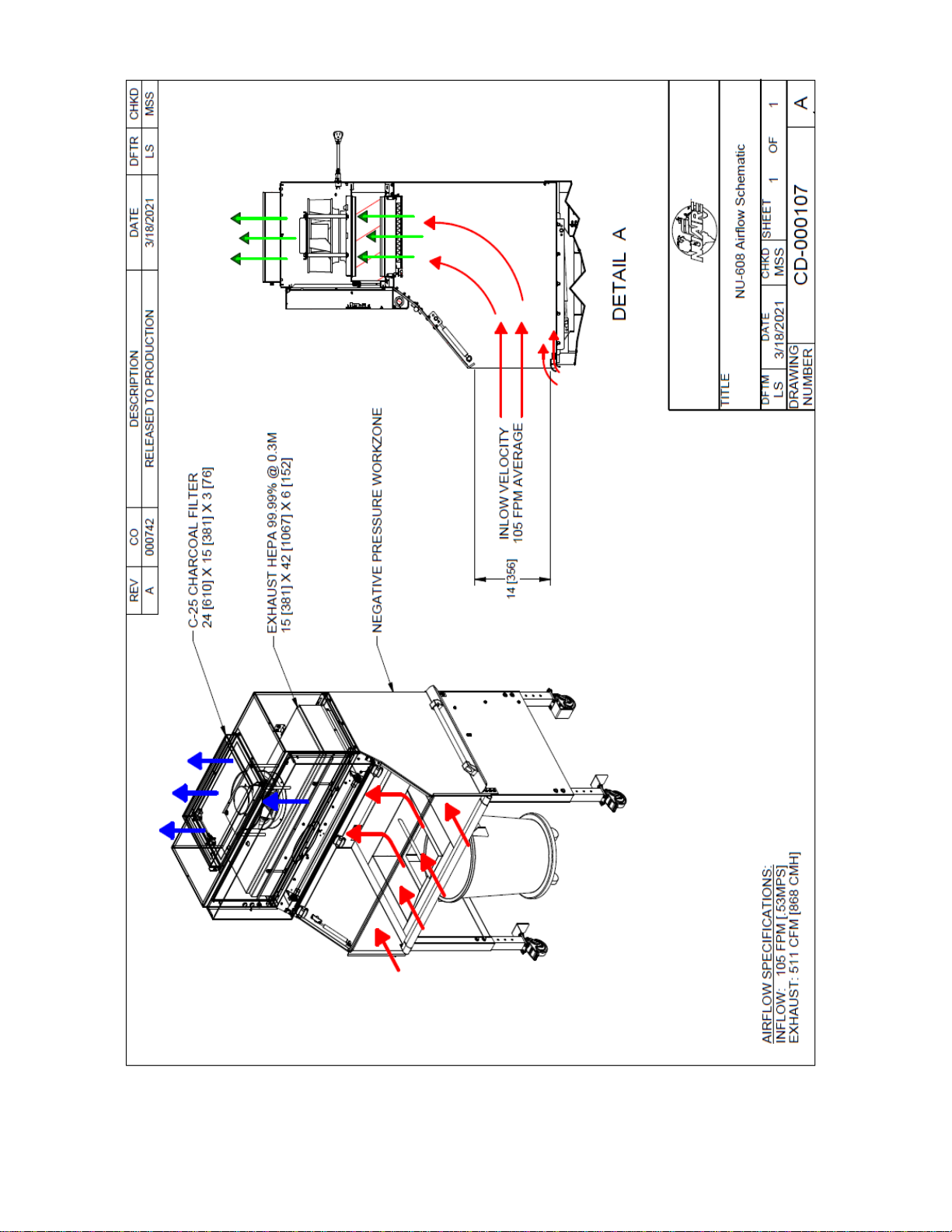
CD-000107..................................NU-608 Airflow Schematic
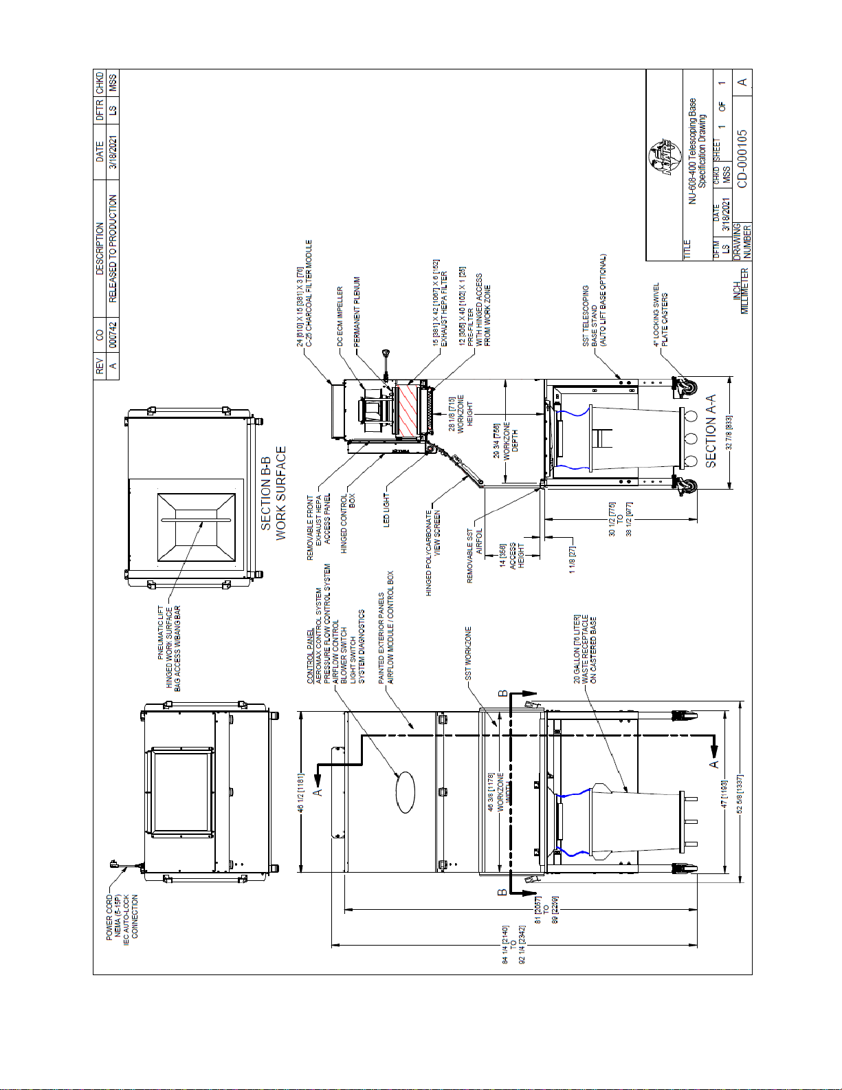
CD-000105..................................NU-608 Spec. Drawing W/Telescoping Base
CD-000109..................................NU-608 Spec. Drawing W/Motorized Base
BCD-16521..................................NU-608 Control Panel
CD-000110..................................NU-608 Final Assembly Drawing
CD-000108..................................NU-608 Electrical Schematic (230VAC)

OM0312
3
Allergard Class I
Animal Bedding Disposal Cabinet
Models:
NU-608-400E
Operation and Maintenance Manual
MANUFACTURED BY:
NuAire, Inc. - Plymouth, Minnesota
1.0 General Description
1.1 Description
The Allergard™ Model NU-608 Class I Animal Bedding Disposal Cabinet is a product resulting from the latest
design innovations, highest quality and newest product features that the Animal Research Professional
demands. The NU-608, with the spacious 14-inch (356mm) work access opening, provides personnel protection
for handling low to moderate risk material, minimizing the risk of exposure to allergens and animal infections
for the laboratory staff. Because a Class I cabinet allows room air to flow over the work surface, the cabinet
does not provide a sterile environment for cage cleaning activity. Refuse disposal bag access is also provided
within the work zone area maintaining containment during the bag installation and removal process.
The NU-608 meets the requirements of a Class I, since the cabinet conforms to the following requirements:
1. Maintains a minimum inflow velocity of 100 LFPM (.51mps) through the work access opening.
2. Discharges air to the outside atmosphere after HEPA filtration.

OM0312
4
1.2 Safety Instructions
These safety instructions describe the safety features of the Allergard™ Model NU-608.
The safety cabinet has been manufactured using the latest technological developments and has been thoroughly tested
before delivery. However, the cabinet may present potential hazards if it is not installed and used as instructed for its
intended purpose or is used outside of operating parameters. Therefore, the following procedures must always be
observed:
•The safety cabinet must be operated only by trained and authorized personnel.
•For any operation of this cabinet, the operator must prepare clear and concise written instructions for operating
and cleaning, utilizing applicable safety data sheets, plant hygiene guidelines, and technical regulations, in
particular.
owhich decontamination measures are to be applied for the cabinet and accessories
owhich protective measures apply while specific agents are used
owhich measures are to be taken in the case of an accident
•Repairs to the device must be carried out only by trained and authorized expert personnel.
•Keep these operating instructions close to the cabinet so that safety instructions and important information are
always accessible.
•Should you encounter problems that are not detailed adequately in the operating instructions, please contact your
NuAire Representative of NuAire technical Services.
1.3 Explanation of Symbols
NOTE:
CAUTION used without the safety alert symbol
indicates a potentially hazardous situation which, if
not avoided, may result in property damage.
Potential electrical hazard, only qualified person to
access.
Used for important information.
Biohazard
Ground, Earth
CAUTION
Chemical Hazard
Flammable Hazard
Hazardous Gases! Personal
Protection Equipment Required.
Lead Free
Safety alert symbol indicates a potentially hazardous
situation which, if not avoided, could result in death of
serious injury.
Safety alert symbol indicates a potentially hazardous
situation which, if not avoided, may result in minor or
moderate injury.
WARNING
!
CAUTION
!

OM0312
5
2.0 Models & Features
The NU-608 is manufactured in one size. 4 ft. (1.2m)

OM0312
6

OM0312
7

OM0312
8

OM0312
9
3.0 Warranty
Details regarding product warranties can be found in the published warranty data separate from this manual and included
within the data packet sent with the unit.
4.0 Shipments
NuAire takes every reasonable precaution to assure that your Allergard cabinet arrives without damage. Motor
carriers are carefully selected and shipping cartons have been specially designed to insure your purchase.
However, damage can occur in any shipment and the following outlines the steps you should take on receipt of
a NuAire Allergard cabinet to be sure that if damage has occurred, the proper claims and actions are taken
immediately.
4.1 Damaged Shipments
4.1.1 Terms are factory, unless stated otherwise. Therefore, it is important to check each shipment before
acceptance.
4.1.2 If there is visible damage, the material can be accepted after the driver makes a notation on the
consignee’s copy of the freight bill. Then an inspection must be made to verify the claim against the
carrier. This inspection is the basis of your filing the claim against the carrier.
4.1.3 If concealed damage is found, it is absolutely necessary to NOTIFY THE FREIGHT AGENT AT ONCE, and
request an inspection. Without this inspection, the transportation company may not accept a claim for
loss or damage. If the carrier will not perform the inspection, an affidavit must be prepared stating that
he was contacted on a certain date and that he failed to comply with the request. This, along with other
papers in the customer’s possession, will support the claim.

OM0312
10
5.0 Installation Instructions
5.1 Location
Within the laboratory, workspace, etc., the ideal location of the NU-608 is away from personnel traffic lanes, air
vents (in or out), doors and/or any other source of disruptive air currents.
SUGGESTED CABINET LOCATION IN LABORATORY
If drafts or other disruptive air currents exceed the intake velocity of the cabinet through the access opening,
the potential exists for contaminated air to exit the cabinet. It depends on the severity of the air current.
Remember, a containment hood is not a substitute for good laboratory technique.
For proper cabinet ventilation, the rear of the NU-608 should be placed no closer than 6 inches (152mm) from
the wall or any object that would impede the exhaust air. The airflow monitor will, however, alert the operator
if insufficient air is being exhausted (or work access inflow velocity).
5.2 Set-Up Instructions
Step 1: Remove from pallet and install casters and safety angles.
Step 2: The charcoal filter is protected from sorption during shipment by a plastic covering, which must be
removed before the unit will function properly (see Section 7.3 for filter removal).
5.3Electrical Services
The NU-608 is provided with a detachable power cord. The station requires 230 VAC, single phase
power and is recommended to be on its own branch circuit, protected with a 15 Amp circuit breaker
at the distribution panel.
Only use Power Cord provided or one with same ratings.
CAUTION
!

OM0312
11
5.4 Certification Testing Methods and Equipment
After installation and prior to use, NuAire recommends that the cabinet be certified or commissioned to factory
standards. At a minimum, the following test should be performed.
1. HEPA filter leak test
2. Airflow velocity
3. Airflow smoke patterns
Of these tests, in order to ensure that no disruptive air currents are penetrating the air inflow barrier smoke
flow tests must be performed. These tests must result in the containment of smoke passed around the
perimeter of the work access opening. A smoke source shall be passed along the entire perimeter of the work
opening edges, approximately 1.5 inches (38mm) outside the cabinet. The smoke shall show a smooth inward
flow with no escape from the work access opening.
IT IS RECOMMENDED THAT THESE TESTS BE PERFORMED BY A QUALIFIED TECHNICIAN WHO IS FAMILIAR
WITH THE METHODS AND PROCEDURES FOR CERTIFYING SAFETY CABINETS.
AFTER THE INITIAL CERTIFICATION, NUAIRE RECOMMENDS THAT THE CABINET BE RECERTIFIED AT A
MINIMUM ON AN ANNUAL BASIS AND AFTER EVERY FILTER CHANGE OR MAINTENANCE ACTION OR ANY TIME
THE OPERATOR FEELS IT IS NECESSARY.
Note that NuAire cabinets, filters and seals provide premium performance; Quality Control in both design and
manufacturing assure superior reliability. However, protection to the operator is so vital that certification to the
performance requirements should be accomplished as stated to ensure safety established by the factory
standards.

OM0312
12
Model
Catalog Number
NU-608-400E
Nominal 4 foot (1.2m)
Performance Specifications
1. Personal Protection
NSF/ANSI 49
NSF Std. No. 49 Class
Class I
Style of Cabinet
Console with integral base
Cabinet Construction
Stainless steel work zone panels and base
with painted steel top blower module.
HEPA Filter Seal Type:
Exhaust Filter-99.99%
Eff. on 0.3 microns
Neoprene,
Spring loaded
Fumigation per NIH/NSF
Procedure
Yes
Cabinet Size Inches (mm):
Height
Depth
Width
84-1/4 to 92-1/4 (2140 to 2342)
32-7/8 (833)
52-5/8 (1337)
Work Access Opening Inches
(mm):
Standard Opening Height/Optional
Standard Inflow Velocity
14 (356)
105 FPM (0.53 m/s)
Work Zone Inches (mm):
Height
Depth
Width
28-1/8 (715)
29-3/4 (756)
46-3/8 (1178)
Viewing window is ¼ in (6mm).
clear polycarbonate
Closed: 14 (356)
Open: 28 (711)
CFM @ 105 FPM
511 CFM (868 CMH)
Heat Rejected, BTU, Per Hour
(non-vented)
1020
Electrical:
Volts, AC 60 Hz
Amps: Blower+
Amps: Lights
Rated Amps:
10 ft. Power Cord (one)
UL/UL-C Listed
230
1.2
.1
5
14 GA - 3 Wire, 15A
Crated Shipping Weight: ***
Net Weight
450 lbs. / 204 kg.
400 lbs. / 181 kg.
+ Based on cabinet with new filters running at 230VAC
***Crated shipping weight does not include weight for accessories or options.

OM0312
13
6.0 Operating the NU-608
6.1 Aeromax™ Control System
6.1.1 Overview
The Aeromax™ control system is designed to service the control requirements of the Allergard NU-608. The
Aeromax™ control system consists of an electronic module that will perform the following functions:
•Easy user interface via LED’s and function keys
•Control blower via solid state switch.
•Control lights via solid state switch.
•Disable audible alarm switch with ring back function.
•Control blower DC EC Impeller with solid-state DC Motor Controller that provides automatic
compensation for line voltage variances.
•Monitor and display airflow system performance via PresurFlow™ monitor.
The Allergard™ NU-608 offers the latest digital microprocessor design technology for improved 608
performance and safety. The Aeromax™ control system integrates a digital pressure sensor
(PresurFlow™) to monitor the NU-608 airflow performance. The Aeromax™ control system also
integrates a EC Impeller controller that provides automatic compensation for both filter loading and line
voltage variances. There is additional on/off control of blower and light. Lastly the Aeromax™ control
system monitors the hinged window position with a micro switch. All the above functions are shown in
a system block diagram (see figure 1).
Figure 1

OM0312
14

OM0312
15
6.1.2 Front Panel
The control system front panel contains the following functions described in detail (see Drawing BCD-
16521).
6.1.2.1 Blower Keys
The blower key controls the ON/OFF power to the blower.
LED above key indicates: full green for blower on,
blinking green for blower pending and
full red for blower alarm.
6.1.2.2 Hidden Key
The hidden key is located just above the blower LED indicator centered in the airflow symbol. The
hidden key is used for various functions including the blower password 3 key sequence if the option
is activated.
6.1.2.3 Light Key
The light key controls the on/off power to the light.
LED above the key indicates full blue for light on.
6.1.2.4 Ultraviolet (UV) Light Key (NOT USED)
6.1.2.5 Outlet Keys (NOT USED)
6.1.2.6 Red Alarm LED
The red alarm LED will indicate any alarm condition and remain indicating until the alarm condition
is cleared.
6.1.2.7 Audible Alarm Silence
The audible alarm silence key allows user interaction to silence an audible alarm for a period of 15
minutes. After 15 minutes if the alarm condition still exists, the audible alarm will again sound.
The audible alarm silence key also is used to exit all Aeromax™ user interaction menus.
6.1.2.8 Arrow Adjustment Keys
The arrow adjustment keys allow user interaction for various functions.
6.1.3 Aeromax™ Control System Power
After the Allergard NU-608 is plugged into the appropriate facility line power the control system will
power up. The control panel will also indicate the power up status by blinking the red alarm LED. Pressing
any key will acknowledge the power up status and turn off the blinking red alarm LED.
If a power interruption occurs, all control system functions, calibrations and parameters will be
maintained and continue upon restoration of power. Just as the initial power up, the red alarm LED will
blink to indicate power up status.
6.1.4 Standby Mode
When the 608 is not in use any of the function keys except the blower that initiates run mode may be
turned on and off in standby mode.

OM0312
16
6.1.5 Run Mode
Any time the blower run key is pressed with the hinged window at its correct operational height, the
RUN MODE screen will be initiated. The Run Mode will start with the PresurFlow™ entering and
approximate 3 minute warm up period. The PresurFlow™ LED indicators will blink and indicate the
following sequence:
•1st minute –Left and right Red LED’s will blink
•2nd minute –Left and right Green LED’s will blink
•3rd minute –Center 3 Green LED’s will blink
Once the warm up period is complete, only one LED will indicate cabinet airflow status.
During the warm up period the cleaning process may begin. If the hinged window is raised, an audible
and visual alarm will occur, but may be silenced by pressing the alarm silence key.
6.1.6 Standby/Run Mode Alarms
If present, standby/run mode alarms will be both visual and audible, the red alarm LED oval will turn on.
Audible alarms will produce an alarm tone for 30 seconds, then ring back for 2 seconds of every 5
seconds. Pressing the alarm silence key will silence the audible alarm for 15 minutes initially then will
start the ring back function again.
The list below represents alarm types and their respective priority from the highest to lowest priority.
1) New Firmware Loaded
2) Internal Board Failure
3) Power on Reset
4) Airflow Pressure Alarm
5) Blower RPM Failure
6) Window Open
Note: The above messages are described in greater detail in section 8.

OM0312
17
6.1.7 Operator Accessible Functions
6.1.7.1 Access and Navigation
To access the operator accessible functions,
•Press and hold the
key, then enter the 3 key sequence for the desired function, then
release
the
key and follow each instruction set.
Note: Pressing the
key at any time will abort and exit the process without saving any
changes made. Pressing the hidden key will accept all changes and exit.
6.1.7.2 Auto Timer Duration
Auto timer duration timers are countdown timers for the functions displayed once time is entered
into a function. The timer will begin to countdown upon the start of that function (i.e. press UV light
key to start timing the UV light). The LED indicator above the function key will start to blink
indicating the timer function. If the LED indicator was full on, no timer function is present. As the
timer expires the function will turn off.
•Select auto timer duration function
oOutlets
Press and hold
key, then press hidden –outlet –outlet keys sequentially.
LED indicator above outlet will blink fast. Adjust desired time as described below.
oLights
Press and hold
key, then press hidden –light –light keys sequentially.
LED indicator above light will blink fast. Adjust desired time as described below.
oUV Light
Press and Hold
key, then press hidden –UV light –UV light keys sequentially.
LED indicator above UV light will blink fast.
Adjust desired time as described below.
•Low Flow Blower
Press and hold
key, then press hidden-blower-blower keys sequentially.
LED indicator above Blower key will blink fast. Adjust desired time as described below.
oAdjust countdown time
Press ↑ or ↓ keys to adjust time.
Time will change in 15 minute increments as shown on the PresurFlow™ LED
segments below.
15 minutes for Red LED 30 Minutes for Yellow LED
1 hour for green LED Represents 8 hours (maximum time)
•Press hidden key to accept time and exit.
•Press
key at any time to abort and exit.

OM0312
18
6.1.7.3 Blower Password
The blower on/off password allows the cabinet user to place a 3 key sequence requirement to turn
the blower on or off.
The 3 key sequence for the blower password will be a combination of the hidden and blower keys.
•Select blower password
Press and hold
key, then press hidden –blower –hidden keys sequentially.
Red LED indicator above blower will blink fast.
•Select password
Press ↑ or ↓ key to scroll through the code choices below,
No Password
B-B-H password
B-H-B password (default)
B-H-H password only
H-B-B password
H-B-H password
H-H-B password
•Press hidden key to accept time and exit.
•Press
key at any time to abort and exit.
Note: If the required blower password option is selected in the blower airflow option menu
(see section 8.2.2). Then the “No password” choice above is not available and the default
remains B-H-B.

OM0312
19
6.2 Operating Guidelines
6.2.1 The intent herein is to present general operating guidelines that will aid in the use of the 608 to control
airborne contaminants of low to moderate risk.
6.2.2 Procedure protocols defined in terms of the barrier of control concepts unique to the 608 must be
developed in order to obtain a maximum potential for safety and protection. The pre-planning
necessary to develop these protocols is based on several fundamental considerations, each of which will
contribute to optimum benefits from the equipment:
a. Minimize disruption of "air curtain"
b. Minimize room activity
c. Employ aseptic techniques
6.2.3 The minimum number of items necessary should be placed into the enclosure to prevent overloading,
but the work should also be planned to minimize the number of times an operator's hands and arms
must enter and leave the air curtain at the open face. The ideal situation is to have everything needed
for the complete procedure place in the enclosure’s workzone before starting, so that nothing need pass
in or out through the air barrier at the face until the procedure is completed. This is especially
important in working with moderate risk agents.
Note: When working with agents of lower risk, it is not as important for all materials to be placed in the
enclosure workzone before starting, or for the procedure to be completely finished before materials are
removed. Also, the time period for a unit of work may be continued over a more extended period
during which entries and withdrawals from the enclosure may be made.
6.2.4 Minimize Room Activity
Activity in the room itself should be held to a minimum. Unnecessary activity may create disruptive air
currents as well as interfere with the work of the operator. A person walking past the front of 608 can
cause draft velocities up to 175 fpm (.88 m/s), which are sufficient to disrupt the air barrier provided by
the work access opening.
6.2.5 Employ Methodical Technique
The operator must not assume an attitude of "let the 608 do it". Properly used, the 608 will do an
excellent job of containing viable or toxic agents. Normal laboratory contamination control procedures
and basic methodical techniques are necessary to obtain maximum benefit from the 608. This
precaution is merely an extension of good laboratory technique as practiced on open bench tops. The
good laboratory practices designed to minimize creating and/or release of aerosols to the environment
should not be discontinued.
In brief, the consideration which should be made in order to obtain optimal personnel safety and
product protection may be reiterated:
a. Pre-plan the procedures carefully
b. Minimize disruption of the "air curtain"
c. Employ aseptic techniques

OM0312
20
6.2.6 Operating Sequence
Start Up - Turn on 608 blower and lights, check air intake and exhaust portals of the unit to make sure
they are unobstructed. Blower speed must only be readjusted by qualified maintenance technicians.
Allow blowers to operate for a minimum of 5 minutes before manipulations are begun in the NU-608. If
the filtered air exhausted from the unit is discharged into the room, as in some installations, an
additional advantage is obtained from purification (filtration) of characteristic contributing to the quality
of the laboratory environment, some owners of NU-608 leave them in operation beyond the time of
actual use.
6.2.7 Wipe down for 608 Operation
The interior surfaces of the work space, if desired should be disinfected by wiping them thoroughly with
70 percent alcohol or similar non-corrosive antimicrobial agent.
NOTE: DISINFECTANTS THAT USE CHLORIDES AND HALOGENS WILL CAUSE DAMAGE TO THE
STAINLESS STEEL SURFACES IF PRESENT AND LEFT ON FOR LONG PERIODS OF TIME.
IF THE DISINFECTANT USED CONTAINS CHLORIDES OR HALOGENS, RE-WIPE ALL
SURFACES
WITH 70% ALCOHOL OR SIMILAR NON-CORROSIVE ANTI-MICROBIAL AGENT TO
PREVENT DAMAGE TO STAINLESS STEEL.
6.2.8 Materials & Equipment
As with any routine task whether it’s in a vivarium or a manufacturing facility, the process set up is
very important not only for efficiency of the task, but also safety. The apparatus and materials should
next be placed into the enclosure workzone. Materials should be arranged so that clean and dirty
(used) materials are well separated. In this case, the supply of dirty cages should be close to the
cabinet, so cages are easily reachable as well as the depositing of cages to whatever material handling
device is used.
6.2.9 Perform work
The work can now be performed. The technician performing the work is encouraged to wear
appropriate personal protective equipment (PPE), (i.e. a long-sleeved gown with knit cuffs, rubber
gloves and appropriate respirator). This will protect the hands and arms from viable agent and
chemical contamination. At a minimum, the hands and arms should be washed well with germicidal
soap before and after work. The cage dump process both the inward motion into the cage dump
cabinet as well as the removal from the cage dump cabinet should be consistent. It doesn’t need to be
slow, just methodical and gaged, not hurried. The cage should always open side up and goes in/out
perpendicular to the front of the cabinet. The actual cage dump itself should be done completely
inside the work area. The work zone would be defined as starting behind the front lip
of the work surface.
6.3.10 Terminal Purging & Wipe down
Following completion of the work, allow the cabinet to run for a 2-3 minute period without personnel
activity to purge the unit. The decontamination of the interior surfaces should be repeated after
removal of all materials, culture, apparatus, etc. A careful check should be made for spilled or splashed
which may contaminate the work environment.
6.2.11 Shut Down
Turn off blowers and lights. Do not use 608 as a depository for excess laboratory equipment during
period of non-operation.
This manual suits for next models
1
Table of contents
Other NuAire Pet Care Product manuals
Popular Pet Care Product manuals by other brands

Walkin’ Pets
Walkin’ Pets Front Wheel Attachment Assembly instructions

MDM
MDM Dog Kennel 7.5'x7.5'x4' Assembly & operation instructions

Roverpet
Roverpet WB2444DSF Assembly instructions

PurrSong
PurrSong LavvieBot S manual

Safety Technology International
Safety Technology International Rex Plus ED-50 Operation manual

Gen7Pets
Gen7Pets G7 Jogger instructions