manuals.online logo
Brands
  1. Home
  2. •
  3. Brands
  4. •
  5. Numa
  6. •
  7. Indoor Furnishing
  8. •
  9. Numa R Series User manual

Numa R Series User manual

This manual suits for next models

4

Popular Indoor Furnishing manuals by other brands

Regency LWMS3015 Assembly instructions

Regency

Regency LWMS3015 Assembly instructions

Furniture of America CM7751C Assembly instructions

Furniture of America

Furniture of America CM7751C Assembly instructions

Safavieh Furniture Estella CNS5731 manual

Safavieh Furniture

Safavieh Furniture Estella CNS5731 manual

PLACES OF STYLE Ovalfuss Assembly instruction

PLACES OF STYLE

PLACES OF STYLE Ovalfuss Assembly instruction

Trasman 1138 Bo1 Assembly manual

Trasman

Trasman 1138 Bo1 Assembly manual

Costway JV10856 manual

Costway

Costway JV10856 manual

moss DESIGN Caisson Credenza Assembly instructions

moss DESIGN

moss DESIGN Caisson Credenza Assembly instructions

Aquaglide FULL DECK 15.0 owner's manual

Aquaglide

Aquaglide FULL DECK 15.0 owner's manual

AREBOS AR-HE-SW30 user manual

AREBOS

AREBOS AR-HE-SW30 user manual

Till-Hilft Fulda 87005.330 Assembly instructions

Till-Hilft

Till-Hilft Fulda 87005.330 Assembly instructions

Twoey Outside 2010 quick start guide

Twoey Outside

Twoey Outside 2010 quick start guide

Hettich Easys 200 operating instructions

Hettich

Hettich Easys 200 operating instructions

The bedboss RELAX 404 Series owner's manual

The bedboss

The bedboss RELAX 404 Series owner's manual

Oeseder Möbelindustrie Bern 991 720 Assembly instructions

Oeseder Möbelindustrie

Oeseder Möbelindustrie Bern 991 720 Assembly instructions

Costway HW68469 user manual

Costway

Costway HW68469 user manual

Next ALIX A27743 Assembly instructions

Next

Next ALIX A27743 Assembly instructions

BROSA Hans Assembly guide

BROSA

BROSA Hans Assembly guide

Prodigg MINIKA PBA015T-FUR installation manual

Prodigg

Prodigg MINIKA PBA015T-FUR installation manual

manuals.online logo
manuals.online logoBrands
  • About & Mission
  • Contact us
  • Privacy Policy
  • Terms and Conditions

Copyright 2025 Manuals.Online. All Rights Reserved.

Installation Manual
Series R
Series R
COSMIC, ORBIS, BANARAS,
ALAMKARA
Congratulations on your purchase of India’s finest Back-Lit mirrors by NUMA.
World class engineering, materials and state of the art design will enable you
to enjoy your mirror for many years to come.
We realize that the marketplace offers many choices and
we thank you for selecting NUMA for your mirror needs.
The following instruction sheets include Models COSMIC, ORBIS, BANARAS,
ALAMKARA
To insure proper installation we recommend installation by a professional installer.
Please use extreme care while unpacking and handling your NUMA mirror
Required Parts
Supplied Parts
(Suction Cups)
Not provided with the mirror.
32mm Electrical
Tape
Anabond
666
RTV Silicone
32mm
SS 304
screws
Cable
Ties
TOP
!
CAUTION
Risk of property damage.
Use anchors for the rated weight
of this product. If re-inforcement
needs to be provided on the wall
on which the product will be
mounted, please take corrective
action on-site.
!
CAUTION
Risk of damage.
If additional hole needs to
be drilled in the mounting
frame for electrical wiring,
NUMA will not be
responsible for any damage
!
CAUTION
Risk of electrical shock
Electrical wiring to be done by
certified electrician only. Reroute
any electrical or water supply
piping afer consulting a
professional.
This document and the information hereto, are the confidential, exclusive property of AGNIFORMA Pvt Ltd. and are
intended only for use for installation for mirror systems purchased from AGNIFORMA pvt. ltd. These documents and
the information contained in these documents may not be distributed, copied, displayed or otherwise used, in whole
or in part, without the prior written permission of AGNIFORMA pvt. ltd. All rights, including all copyright rights in
these documents and the information contained in these documents, are expressly reserved.
Page 1
Mark mirror & frame lines. Make sure the marking is completely horizontal.
The frame is smaller than the mirror by 12mm (0.5inch) on all 4 sides
Location of Electrical
Point (Mirror centre
unless otherwise
customized)
Top Mirror Line
Top Frame Line
12mm
Bottom
Frame Line
Bottom Mirror
Line
12mm
1
Ensure electrical outlet in the wall matches the outlet provided in our framing system.
2
This document and the information hereto, are the confidential, exclusive property of AGNIFORMA Pvt Ltd. and are
intended only for use for installation for mirror systems purchased from AGNIFORMA pvt. ltd. These documents and
the information contained in these documents may not be distributed, copied, displayed or otherwise used, in whole
or in part, without the prior written permission of AGNIFORMA pvt. ltd. All rights, including all copyright rights in
these documents and the information contained in these documents, are expressly reserved.
Page 2
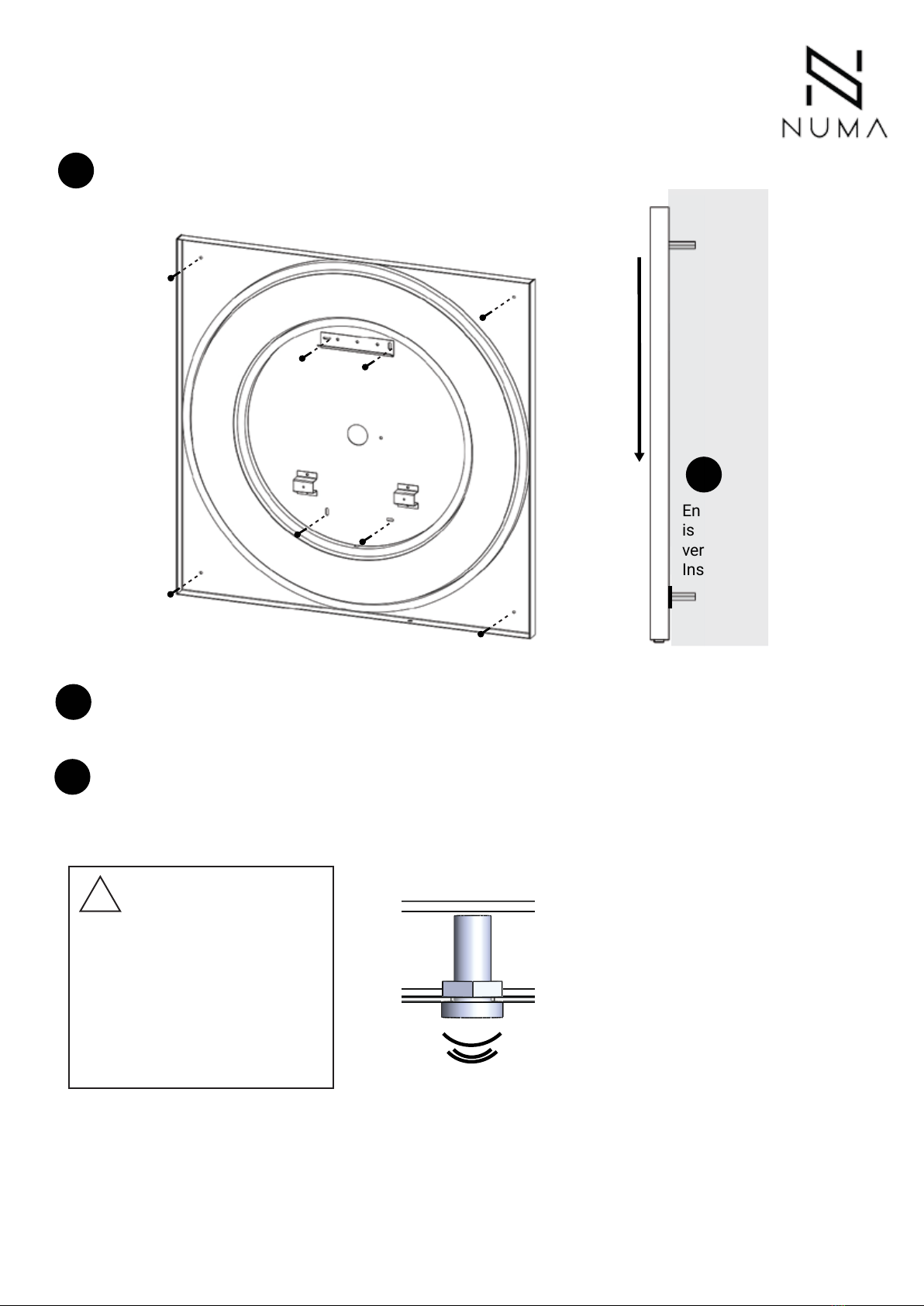
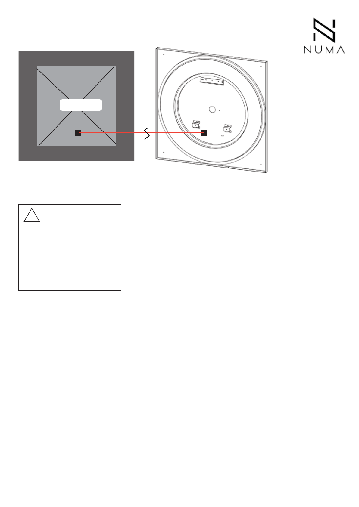
Fix the frame onto the wall using rated anchors. Once the frame is affixed, kindly
complete electrical wiring. Please note a grounding wire (green) is provided with the
system.
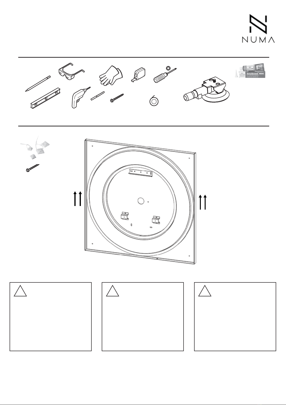
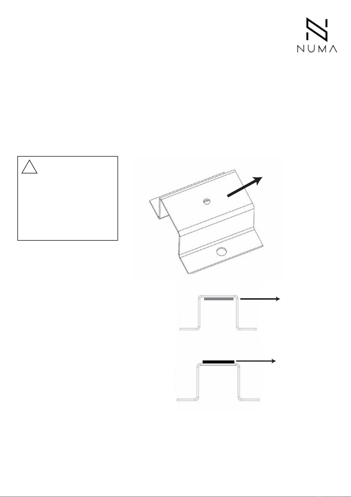
For longer or heavier mirrors, additional holes maybe be provided for anchoring onto
the wall
3
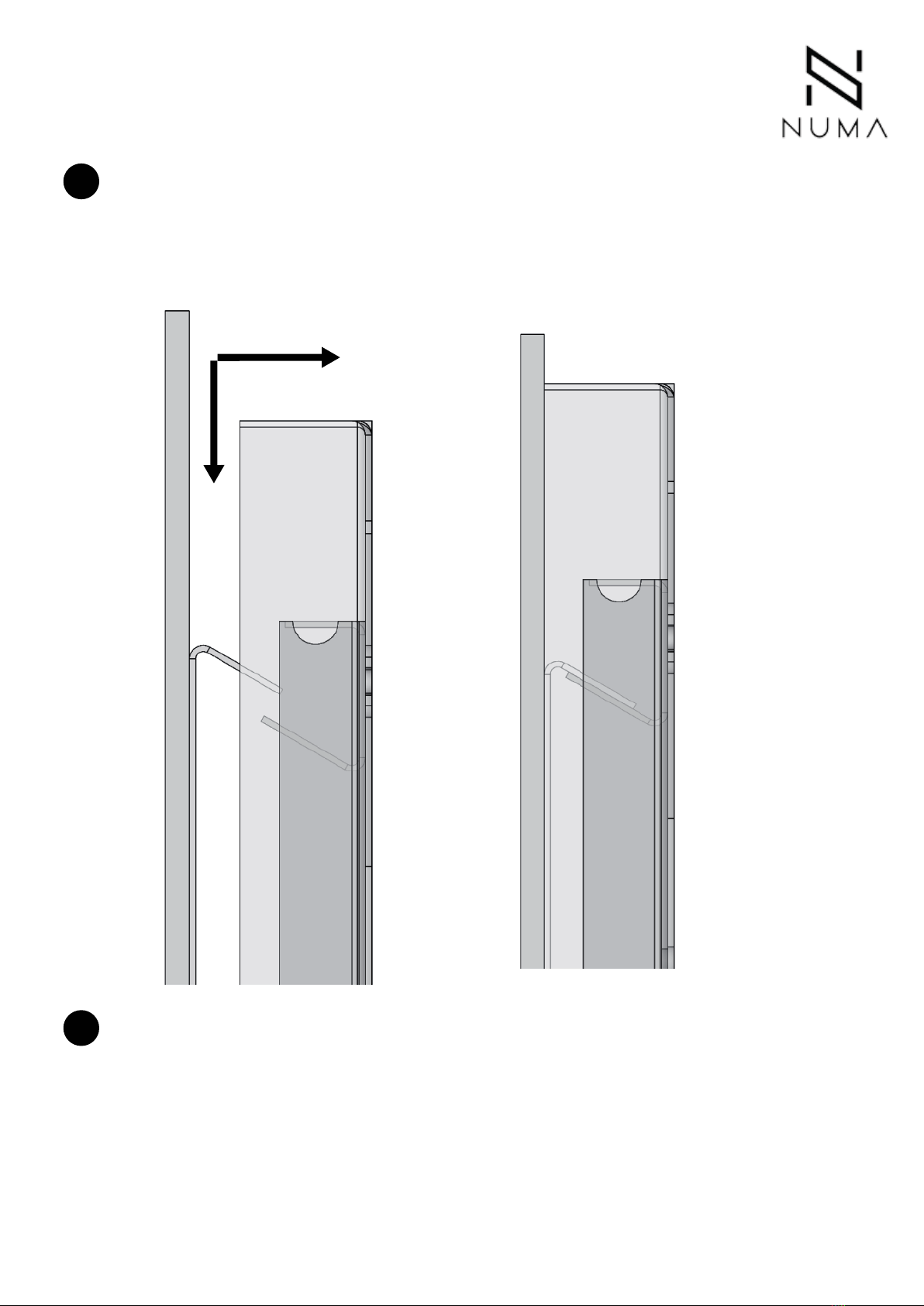
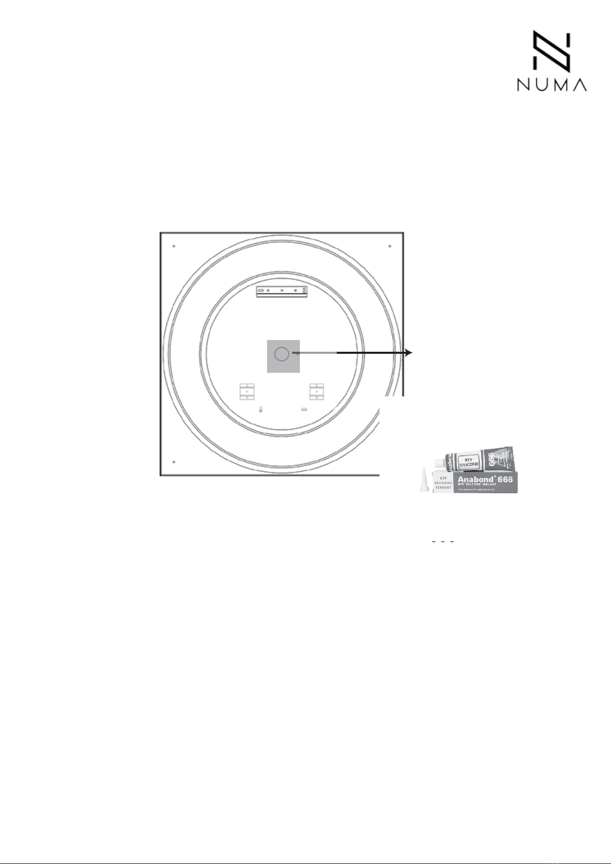
After electrical wiring is complete, kindly switch on to make sure the LEDs are turning
on and off through the sensor (if provided), or through switching the external power
supply on and off.
5
6
!
CAUTION
Risk of electrical shock
Please do not connect the
grounding wire to the live
terminal, as you will risk electrical
shock from the casing. Wave your hand underneath the
sensor to turn the LEDs on and off
Ensure that the mirror
is perfectly
vertical
Insert packing if necessary
Straight
4
This document and the information hereto, are the confidential, exclusive property of AGNIFORMA Pvt Ltd. and are
intended only for use for installation for mirror systems purchased from AGNIFORMA pvt. ltd. These documents and
the information contained in these documents may not be distributed, copied, displayed or otherwise used, in whole
or in part, without the prior written permission of AGNIFORMA pvt. ltd. All rights, including all copyright rights in
these documents and the information contained in these documents, are expressly reserved.
Page 3
Using a set of suction cups, position the mirror carefully over the mounting frame,
such that the angular mating part on the mirror, rests on the top of the angular surface
on the mounting frame. The mirror extends 12mm or 0.5 inch from the mounting
frame on all 4 sides.
7
8After mounting the frame, if there is a gap between the mirror and the frame, push the
mirror gently towards the frame, so that the magnets on the mounting mirror clasps the
metal frame on the mirror. If there is a gap between the mirror and the frame, kindly
check the leveling of the mirror with the wall, to ensure that it is mounted completely
straight/vertical. Use packing at the rear of the frame, if neccessary.
This document and the information hereto, are the confidential, exclusive property of AGNIFORMA Pvt Ltd. and are
intended only for use for installation for mirror systems purchased from AGNIFORMA pvt. ltd. These documents and
the information contained in these documents may not be distributed, copied, displayed or otherwise used, in whole
or in part, without the prior written permission of AGNIFORMA pvt. ltd. All rights, including all copyright rights in
these documents and the information contained in these documents, are expressly reserved.
Page 4
The DeFogger/DeMister is mounted on the mirror;
Before mounting the mirror, it is necessary to connect the wiring/terminals of the de-fogger
with the appropriate connector on the rear-frame.
While mounting the mirror onto the rear-frame, ensure that the wiring of the de-fogger is not
damaged or scratached in any manner and the excess wiring does not interfere with the
lighting or design.
Use the supplied tie-s or an electrical tape (not provided) to secure the excess wiring length.
DeFogger
Mirror
Connector
provision in the rear-frame
!
CAUTION
Risk of electrical shock
Electrical wiring to be done by
certified electrician only.
De-Fogger
This document and the information hereto, are the confidential, exclusive property of AGNIFORMA Pvt Ltd. and are
intended only for use for installation for mirror systems purchased from AGNIFORMA pvt. ltd. These documents and
the information contained in these documents may not be distributed, copied, displayed or otherwise used, in whole
or in part, without the prior written permission of AGNIFORMA pvt. ltd. All rights, including all copyright rights in
these documents and the information contained in these documents, are expressly reserved.
Page 5
Please note that strong magents are provided with each frame to adhere the mirror to the
rear- frame.
You will find them below the brackets; kindly place them above the brackets after installation
of the rear frame and before you hang the mirror.
The adhesion strength of these magnets is very high and please take proper care when
you are placing or removing the mirror; do not pull the mirror from one side; use equal force
across the length of the mirror to avoid breakage.
Magnets
!
CAUTION
Risk of mirror damage
Please apply equal force
across the width of the mirror
during installation or removal.
Do not pull or push from any
one side, across the width.
Place Magnets
on this surface
(TOP)
Bracket for Magnet
Final Position
Position during
storage &
transit
This document and the information hereto, are the confidential, exclusive property of AGNIFORMA Pvt Ltd. and are
intended only for use for installation for mirror systems purchased from AGNIFORMA pvt. ltd. These documents and
the information contained in these documents may not be distributed, copied, displayed or otherwise used, in whole
or in part, without the prior written permission of AGNIFORMA pvt. ltd. All rights, including all copyright rights in
these documents and the information contained in these documents, are expressly reserved.
Page 6
To avoid steam or water vapor from entering the mirror, flexible silicone sheet is provided
(red color) onto the rear frame.
For electrical outlet, kindly punch a hole through this silicone sheet, wherever required and
after completion of wiring, apply silicone such as Anabond 666 around the wire to seal the
excess space.
Sealing Frame after wiring.
Anabond
666
RTV Silicone
Punch a hole
through this silicone
sheet for wiring
and seal after
completion around
the wire.
This document and the information hereto, are the confidential, exclusive property of AGNIFORMA Pvt Ltd. and are
intended only for use for installation for mirror systems purchased from AGNIFORMA pvt. ltd. These documents and
the information contained in these documents may not be distributed, copied, displayed or otherwise used, in whole
or in part, without the prior written permission of AGNIFORMA pvt. ltd. All rights, including all copyright rights in
these documents and the information contained in these documents, are expressly reserved.
Page 7