SNC-300 non-addressable smoke/heat detector
Installation Instructions
www.numens.net 1 32-0032-r02_2015-05
Cautions
ELECTRICAL HAZARD: Disconnect power from equipment prior to making
any internal adjustments. Service should only be performed by qualified
personnel.
FRAGILE: Inspect the equipment prior to installation. Do not install the
equipment if damage is apparent. Do not attempt to disassemble this
equipment. If damaged, return to the supplier.
ELECTROSTATIC HAZARD: This is sensitive electronic equipment. Apply
safe ant-static practices when handling this equipment.
CIRCUIT LIMITATIONS: The maximum number of detectors connected to
a single detection zone is limited by the control and indicating equipment,
and may be limited by local regulations.
Introduction
SNC-300 non-addressable photoelectric smoke/heat detectors are
state-of-the-art detectors suitable for connection to 2-wire or 4-
wire non-addressable fire detection control and indicating
equipment, or to addressable fire detection control and indicating
equipment that can accept non-addressable type detectors
1
.
These instructions provide trained installation personnel with
details to install and commission SNC-300 smoke/heat detectors
for optimum performance.
Preparation
Before commencing installation, ensure all equipment (base and
detector) and tools to mount and connect the equipment are
available, such as drills, mounting screws, cables and ladders.
SNC-300 smoke/heat detectors can be installed with the following
bases and accessories.
Description Part number Datasheet
5-terminal 102 mm low profile base CN3023 31-0035
5-terminal 102 mm low profile base
a
CN3021 31-0035
9-terminal 102 mm low profile base CN3043 31-0037
9-terminal 102 mm low profile base
a
CN3041 31-0037
Detector monitor module 620-001 31-0027
Remote indicator
b
681-001 31-0034
a
UL-approved.
b
Requires 9-terminal base.
Installation
Base
The base can be mounted directly onto an electrical junction box
such as an octagonal (75 mm, 90 mm or 100 mm), a round
(75 mm), or a square (100 mm) box without using any type of
mechanical adapter.
1. Feed the conductors through the middle of the base for
termination to the base contacts.
2. Mount the base on the junction box or directly onto a flat
surface.
3. Mount the base to the surface using fixing screws that are
suitable to securely fix the base to the surface.
Wiring
Base terminals accept (0.4 ~ 2.5) mm
2
conductors.
1. Strip the conductor insulation to expose 5 mm of the
conductor.
2. Connect the conductors to the base terminals.
a. See Fig. 1 for detectors using 2-wire bases.
b. See Fig. 2 for detectors using 4-wire bases.
WARNING: Take care to ensure the insulation does not get
clamped by the terminal contact.
1
May be used with the 620-001 detector monitor module.
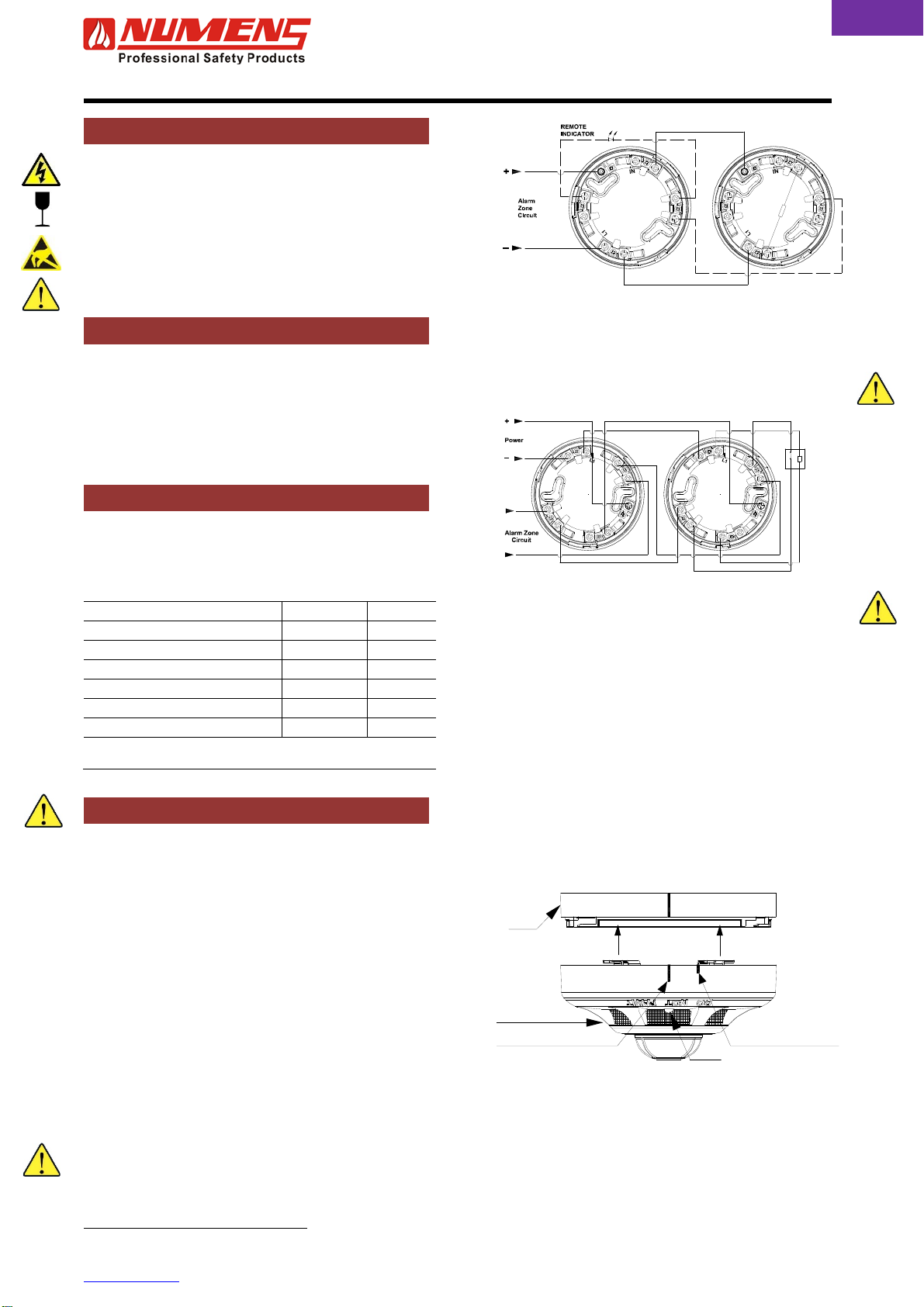
Fig. 1: 2-wire base wiring connections
Note 1: 9-terminal base required if a remote indicator is installed.
Note 2: If a remote indicator is not installed, the polarity of the zone circuit
wiring may be reversed.
WARNING: Do not short-circuit terminals 2 and 5.
Fig. 2: 4-wire base wiring connections
WARNING: Do not short-circuit terminals 2 and 5.
3. After all the bases are installed and wired, fit the end-of-line
resistor.
Note: The value of the end-of-line resistor depends on the control and
indicating equipment to which the detectors are installed.
4. Check the wiring for continuity, short circuits and earth faults.
Output Relay (where fitted)
The output relay is factory-adjusted with normally-open contacts
that close on alarm. No setting adjustment is required.
Detector
WARNING: Do not install the detector head until the area is
thoroughly cleaned of construction debris, dust, etc.
1. Align the detector alignment mark with the short alignment
mark in the base, as shown in Fig. 3.
2. Mate the detector head onto the base and rotate it clockwise
to secure it. The long alignment marks should be aligned.
Fig. 3: Fitting the detector to the base
5
L2
4
_
3
R
2
L1
1
6
OUT
4
_R
3
2
L1
1
6
OUT
5
L2
End-of-line
device
1
6
OUT
5
L2
4
3
R
_
L1
IN
2
1
6
OUT
5
L2
4
3
_
R
L1
IN
2
Optional
Power
Supervision
Relay
Detector head
LED
Short AlignmentMark
Long AlignmentMark
Base


